
Related Manuals for JBL PRX500 Series


Summary of Contents for JBL PRX500 Series
- Page 1 U s e r ’ s G u i d e...
-
Page 3: Table Of Contents
CONTENTS Important Safety Instructions Precautions The PRX500 Series Power Amplifier 8 - 9 Introduction To The PRX500 Series System Specifications 11 - 15 System Setup 16 - 19 Setting Input Sensitivity Setting The Gain Application Examples 22 - 25 Reference... -
Page 4: Important Safety Instructions
Care And Cleaning PRX500 series systems may be cleaned with a dry cloth. Do not get moisture into any of the openings in the system. Ensure that the system is unplugged from the AC outlet before cleaning. In the event the DuraFlex finish is damaged a touch up kit can be obtained from JBL Professional (part number 363972-001). -
Page 5: Precautions
Stand Mounting Safety Precautions Some PRX500 series models include a 36 mm receptacle cup to allow mounting on tripod stands or on a pole over subwoofers. When using stands or poles, be sure to observe the following precautions: •... -
Page 6: Watch For These Symbols
WATCH FOR THESE SYMBOLS! C A U T I O N WARNING - TO REDUCE THE RISK OF ELECTRIC SHOCK RISK OF FIRE OR ELECTRIC SHOCK, DO NOT OPEN DO NOT EXPOSE THIS EQUIPMENT TO RAIN OR MOISTURE. RISQUE DE CHOC ELECTRIQUE NE PAS OUVRIR The lightning flash with arrowhead symbol within The exclamation point within an equi-lateral triangle is... - Page 7 PRX500 Series speakers Declaration of Conformity Safety And EMC Compliance Specifications EN 55103-1:1997 Electromagnetic Compatibility - Product Family Standard for Audio, Video, Audio-Visual and Entertainment Lighting Control Apparatus for Professional Use, Part 1: Emissions EN 55103-1:1997 Magnetic Field Emissions-Annex A @ 10 cm and 20 cm EN 55022:2003 Limits and Methods of Measurement of Radio Disturbance Characteristics of ITE: Radiated, Class B Limits;...
-
Page 8: The Prx500 Series Power Amplifier
Your PRX500 series speaker will typically be set at the factory to accommodate the power mains voltage in your area. Before you set up your PRX500 series speaker for the first time it is a good idea to verify that the setting of the selector is appropriate for the power in your area. - Page 9 Operating Temperature The design of the Crown amplifier is such that it is very energy efficient and as a result does not get really hot. In the rare event that it does get too hot it will automatically shut down to protect itself. When its temperature has returned to within its operating range it will turn back on.
-
Page 10: Introduction To The Prx500 Series
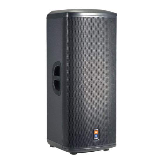
PRX525 PRX535 Thank you for choosing the JBL PRX500 series self-powered PA loudspeakers. There are five models in the series, four full-range systems and one subwoofer. All are powered by integrated digital power amplifiers developed by Crown, the most trusted name in professional sound reinforcement power amplification. In addition to Crown power amplifiers, the systems are equipped with sophisticated DSP for EQ, crossover, system control and protection. -
Page 11: System Specifications
® LF Driver: 1 x JBL 262F 380 mm (12 in) Differential Drive woofer HF Driver: 1 x JBL 2408H 37.5 mm (1.5 in) annular polymer diaphragm, neodymium compression driver Enclosure: Trapezoidal, 18 mm, plywood Suspension / Mounting: Dual 36mm pole socket... - Page 12 LF Driver: 1 x JBL 265F 380 mm (15 in) Differential Drive woofer HF Driver: 1 x JBL 2408H 37.5 mm (1.5 in) annular polymer diaphragm, neodymium compression driver Enclosure: Trapezoidal, 18 mm, plywood with polypropylene end caps Suspension / Mounting:...
- Page 13 ® LF Driver: 2 x JBL 265F 380 mm (15 in) Differential Drive woofer HF Driver: 1 x JBL 2408H 37.5 mm (1.5 in) annular polymer diaphragm, neodymium compression driver Enclosure: Trapezoidal, 18 mm, plywood with polypropylene end caps Transport:...
- Page 14 MF Driver: 1 x JBL 195H, 165 mm (6.5 in) woofer HF Driver: 1 x JBL 2414H 25 mm (1.0 in) annular polymer diaphragm, neodymium HF compression driver Enclosure: Trapezoidal, 18 mm, plywood with polypropylene end caps Suspension / Mounting:...
- Page 15 -25 dBu to 0 dBu Input Impedance: 34K Ohms (balanced), 18K Ohms (unbalanced) Polarity: 0° or 180° phase shift LF Driver: 1 x JBL 2044E 460 mm (18 in) woofer Enclosure: Rectangular, 18 mm, plywood Suspension / Mounting: 36mm pole socket on top Transport:...
-
Page 16: System Setup
PRX515 LEVEL BOOST OVERLOAD SIGNAL POWER FLAT LINE LINE SELECT JBL PROFESSIONAL Northridge, CA. USA AC LINE INPUT 100V~ -240V~ 50/60 Hz 5A 600W ® Equipped with Differential Drive Transducer Technology U.S. PATENT 5,748,760 Other U.S. and foreign patents pending... - Page 17 2 - INPUT MIC / LINE: Allows the selection of different input sensitivities to permit the connection of many different sources, with or without the use of a mixer or external microphone preamplifier. See “Setting Input Sensitivity” on page 18. 3 - LEVEL: Sound level adjustment.
- Page 18 PRX500 Amplifier Input Configuration for PRX518S Subwoofer Model: XOVER POLARITY PRX518S LEVEL OVERLOAD SIGNAL POWER LINE SELECT JBL PROFESSIONAL Northridge, CA. USA AC LINE INPUT 100V~ -240V~ CSA Certification applies to LEFT RIGHT 50/60 Hz 5A 600W Amplifier Module Only CSA Certificated to operate...
- Page 19 3 - LEVEL: Sound level adjustment. The 12 o’clock position is a good starting point for most usages. Once the full-range system has been connected the level can be varied to match and deliver the desired balance (for details see Setting the Gain on page 21). 6 - POWER SWITCH: Turns the power on.
-
Page 20: Setting Input Sensitivity
SETTING THE INPUT SENSITIVITY PRX500 series systems have been designed to allow the connection of a variety of sources. This provides a great deal of versatility, especially with the PRX512M and PRX515, as a microphone or instrument can be connected directly to the input. -
Page 21: Setting The Gain
+4 dB signal), set the “Level” control to the 12 o’clock position, and adjust until the “overload” LED just begins to flicker. For in depth articles related to gain structure please refer the website where you can find the JBL Sound System Design Reference Manual; http://www.jblpro.com/pub/technote/ssdm_99.pdf... -
Page 22: Application Examples
Basic Sound Reinforcement System This is a very basic sound system. PRX500 series speakers allow the direct connection of sound sources, without the need for extra mixer or pre-amplifier. The XLR or 1/4 inch input jack provides versatility and cabling options and the mic/line input sensitivity selector switch optimizes the speaker gain for the input source. - Page 23 PRX512M LEVEL MAIN OVERLOAD SIGNAL POWER MONITOR LINE LINE SELECT JBL PROFESSIONAL Northridge, CA. USA AC LINE INPUT 100V~ -240V~ 50/60 Hz 5A 600W ® Equipped with Differential Drive Transducer Technology U.S. PATENT 5,748,760 Other U.S. and foreign patents pending...
- Page 24 LEVEL BOOST OVERLOAD SIGNAL POWER FLAT LINE Right Main Output LINE SELECT JBL PROFESSIONAL Northridge, CA. USA AC LINE INPUT 100V~ -240V~ 50/60 Hz 5A 600W ® Equipped with Differential Drive Transducer Technology U.S. PATENT 5,748,760 Other U.S. and foreign patents pending...
- Page 25 PRX525 LEVEL BOOST OVERLOAD SIGNAL POWER FLAT LINE LINE SELECT JBL PROFESSIONAL Northridge, CA. USA AC LINE INPUT 100V~ -240V~ 50/60 Hz 5A 600W Equipped with Differential Drive ® Transducer Technology U.S. PATENT 5,748,760 Other U.S. and foreign patents pending...
-
Page 26: Reference
REFERENCE Balanced vs. Unbalanced Lines Your PRX500 series can accept either type of input. There are two basic types of audio system interconnections for audio signals: Balanced and Unbalanced. Balanced Lines In audio, a balanced line is a three-conductor system in which the two signal wires carry an equal, but opposite voltage with respect to the ground wire. -
Page 27: Cables And Connectors
CABLES AND CONNECTORS XLR/F to XLR/M Microphone Cable The standard cable for interconnection of microphone and line level signal in professional audio systems. • Microphone to mixer • Microphone to PRX500 direct input • Professional audio mixer to PRX500 • Daisy chaining PRX500 speakers TRS (balanced) 1/4 inch phone jack For connecting balanced devices with 1/4 inch phone and maybe to XLR/M... -
Page 28: Troubleshooting
TROUBLESHOOTING Symptom Likely Cause What To Do No sound. Speaker not connected to Verify that speaker is connected active AC power. and that the circuit is on. Switch on power and verify that illuminated logo is on. • Re-seat the power cable at both ends. Speaker power Cable is faulty •... - Page 29 Noise or hiss heard at output Noisy Source Device Disconnect the devices that are connected to your speaker one at a time. If the noise goes away, the problem is with the source or the connecting cable. Disconnect or mute channels one at a time to Hum or Buzz that increases or Improper A/C ground or faulty isolate the problem.
-
Page 30: Contact Information
On The World Wide Web: www.jblpro.com Professional Contacts, Outside The USA: Contact the JBL Professional Distributor in your area. A complete list of JBL Professional international distributors is provided at our U.S.A. website -www.jblpro.com Product Registration: Register your product online at www.jblpro.com/registration... -
Page 31: Warranty Information
Department),8500 Balboa Boulevard, PO. Box 2200,Northridge,California 91329 (818/893-8411). We may direct you to an authorized JBL Service Agency or ask you to send your unit to the factory for repair. Either way, you'll need to present the original bill of sale to establish the date of purchase. Please do not ship your JBL product to the factory without prior authorization. - Page 32 8500 Balboa Boulevard Northridge, CA 91329 USA Part Number: 363264-002 8/2008 Visit us online at www.jblpro.com...