
Related Manuals for Patton electronics 2041


Summary of Contents for Patton electronics 2041
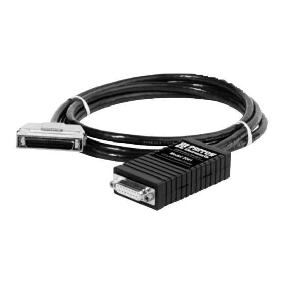
- Page 1 USER MANUAL MODEL 2041 X.21 to HSSI Interface Converter SALES OFFICE Part# 07M2041-A Doc# 077241U, (301) 975-1000 Rev. B TECHNICAL SUPPORT Revised 1/23/08 (301) 975-1007 An ISO-9001 http://www.patton.com Certified Company...
-
Page 2: Radio And Tv Interference
However, there is no guarantee that interference will not occur in a particular installation. If the Model 2041 does cause interference to radio or television reception, which can be... - Page 3 NOTE: Packages received without an RMA number will not be accepted. Patton Electronics' technical staff is also available to answer any questions that might arise concerning the installation or use of your Model 2041. Technical Service hours: 8AM to 5PM EST, Monday through Friday.
-
Page 4: General Information
X.21 interface communicate bi- directionally with a device that has an HSSI interface. Operating up to a top synchronous data rate of 10Mbps, the 2041 is a perfect problem solver for mismatched interfaces. - Page 5 The following instructions will help you set up and install the Model 2041 properly. To use the Patton Model 2041, you must first configure the unit for your application. To do so, first open the case by inserting a flat head screw driver into an open slot on either side of the case, as in Figure 1.
- Page 6 3.1 CONFIGURATION SWITCHES (MODELS 2041FT-MC) The Model 2041FT-MC has miniature DIP switches that you may use to configure the units. Each Model 2041FT-MC is factory configured as DTE on the X.21 end, and DCE on the HSSI end. Therefore, the X.21 end “wants” to plug directly into a DCE device. Conversely, the HSSI end of the converter “wants”...
- Page 7 2041FT-MC DIP SWITCH SUMMARY TABLE Position Function Factory Default Sync Method Bypass Sync Circuit Sync Method LED Operation LED control by I and TA LED Operation Switches S1 and S2: Synchronization Method Set Switches S1 and S2 together to allow the Model 2041FT-MC to compensate for timing delays when transmitting HSSI data at high speeds (greater than 2.5 Mbps).
- Page 8 3.2 CONFIGURATION SWITCHES (MODELS 2041FC-MT) The Model 2041FC-MT has miniature DIP switches that you may use to configure the units. Each Model 2041FC-MT is factory configured as DCE on the X.21 end, and DTE on the HSSI end. Therefore, the X.21 end “wants” to plug directly into a DTE device. Conversely, the HSSI end of the converter “wants”...
- Page 9 2041FC-MT DIP SWITCH SUMMARY TABLE Position Function Factory Default LED Operation LED controlled by”C” or “DTR” LED Operation Sync Method Bypass Sync Circuit Sync Method Switches S1 and S2: Status LED Operation Set Switches S1 and S2 together to determine the how the Status LED on the 2041FC-MT triggers.
-
Page 10: Installation
4.0 INSTALLATION The Model 2041 is designed to connect X.21 devices to devices which employ the HSSI interface standard. This section describes how to install the units. 4.2 2041FT-MC CONNECTION The Model 2041FT-MC is designed to connect a X.21 DCE device to an HSSI DTE device. -
Page 11: Ac Power Connection
IEC-320 power entry connector and supports a voltage range of 100-250VAC. This transformer connects to the Model 2041 by means of a cannon jack on the rear panel. There are a variety of domestic and international power cords available for the power entry (See Appendix B). -
Page 12: Back Panel Led Status Monitors
5.1 BACK PANEL LED STATUS MONITORS The Model 2041 features two LEDs that are located on the back panel. Figure 9 below shows the positions of the LEDs. Following Figure 9 is a description of each LED. - Page 13 APPENDIX A PATTON MODEL 2041 SPECIFICATIONS Data Format: Synchronous Data Rate: 0 - 10Mbps Clocking: All HSSI co-directional timing patterns are supported. Standards: Converts ITU/CCITT X.21 to HSSI (ANSI/TIA/EIA- 613 Dec. “93 and ANSI/TIA/EIA-612 NOV. “93) electrically and mechanically. Loopbacks:...
- Page 14 APPENDIX B PATTON MODEL 2041 FACTORY REPLACEMENT PARTS AND ACCESSORIES Patton Model # Description 08055DCUI......100-240VAC (+5V ±5% reg. DC/2A) Universal Input Adapter 0805EUR......European Power Cord CEE 7 0805UK ......United Kingdom Power Cord 0805US ......American Power Cord 0805AUS ......Australia/New Zealand Power Cord 0805DEN......Denmark Power Cord...
- Page 15 APPENDIX C PATTON MODEL 2041 HSSI INTERFACE HD-50 CONNECTOR (DCE OR DTE) Pin # Signal SGND (Signal Ground) SGND (Signal Ground) RT (Receive Timing-A) RT/ (Receive Timing-B) DSR/(DCE Ready-A) DSR (DCE Ready-B) RD (Receive Data-A) RD/ (Receive Data-B) Reserved for Future Use...
- Page 16 APPENDIX C PATTON MODEL 2041 X.21 INTERFACE DB-15 CONNECTOR (X.21 DCE OR DTE) Pin # Signal FG (Frame Ground) T (Transmit - A) C (Control - A) R (Receive - A) I (Indication - A) ST (Signal Timing - A)
- Page 20 Dear Valued Customer, Thank you for purchasing Patton Electronics products! We do appreciate your business. I trust that you find this user manual helpful. We manufacture one of the widest selections of data communications products in the world including CSU/DSU's, network termination units, powered and self-powered short range modems, fiber optic modems, interface converters, baluns, electronic data switches, data-line surge protectors, multiplexers, transceivers, hubs, print servers and much more.