Table of Contents
Advertisement
Quick Links
Advertisement
Table of Contents

Summary of Contents for Patton electronics 2070 Series
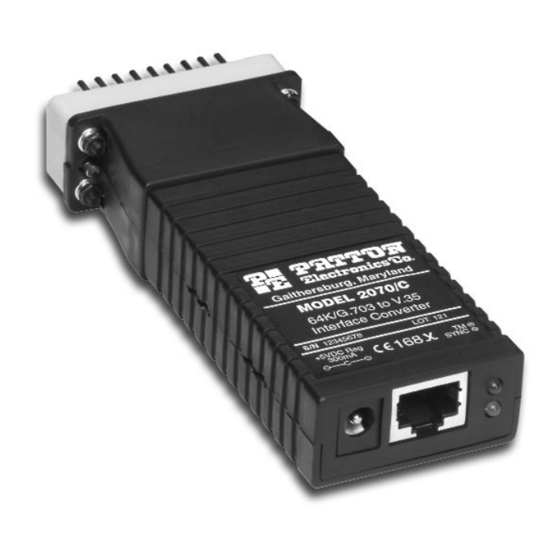
- Page 1 USER MANUAL Model 2070 Series V.24/X.21/V.35 to G.703 Interface Converter SALES OFFICE Part# 07M2070-UM (301) 975-1000 Doc# 03106U2-001, Rev. D TECHNICAL SUPPORT C E R T I F I E D Revised 10/25/06 (301) 975-1007 An ISO-9001 http://www.patton.com Certified Company...
-
Page 2: Table Of Contents
1.0 WARRANTY INFORMATION TABLE OF CONTENTS Patton Electronics warrants all Model 2070 Series components to Section Page be free from defects, and will—at our option—repair or replace the product should it fail within one year from the first date of shipment. -
Page 3: Ce Notice
2.0 GENERAL INFORMATION 1.2 CE NOTICE Thank you for your purchase of this Patton Electronics product. The CE symbol on your Patton Electronics equipment indicates This product has been thoroughly inspected and tested and is that it is in compliance with the Electromagnetic Compatibility (EMC) warranted for One Year parts and labor. -
Page 4: Configuration
3.2 CONFIGURATION (MODEL 2070/Ax V.24 VERSION) 3.0 CONFIGURATION The Model 2070/Ax uses a mini DIP switch package and jumper The Model 2070 is easy to install and is ruggedly designed for strap that allow configuration to a wide range of applications. The excellent reliability. - Page 5 Switch S1-4: Response to DTE Request for Local Loopback 2070/Ax SWITCH S1 SUMMARY TABLE Position Function Factory Default Use Switch S1-4 to enable the Model 2070/Ax to enter Local S1-1 Test Mode Disabled Loopback mode when pin 18 from the V.24 interface is raised. In the On position, the Local Loopback may only be enabled manually by S1-2 Clock Mode...
-
Page 6: Configuration
3.3 CONFIGURATION (MODEL 2070/Cx -- V.35 VERSION) 2070/Ax JP1 AND JP2 SUMMARY TABLE The Model 2070/Cx uses a mini DIP switch package and a jumper Position Function Factory Default strap that allow configuration to a wide range of applications. The Power Source 1&3 AC Powered switch is located on the bottom side and the jumper strap is located on... - Page 7 MODEL 2070/Cx SWITCH S1 SUMMARY TABLE Switch S1-4: Response to DTE Request for Local Loopback Position Function Factory Default Use Switch S1-4 to enable the Model 2070/Cx to enter Local S1-1 Test Mode Disabled Loopback mode when pin L from the V.35 interface is raised. In the On S1-2 Clock Mode Network...
-
Page 8: Configuration
3.4 CONFIGURATION (MODEL 2070/Dx -- X.21 VERSION) 2070/Cx JP1 AND JP2 SUMMARY TABLE Position Function Factory Default The Model 2070/Dx uses a mini DIP switch package and a jumper strap that allow configuration to a wide range of applications. The Power Source 1&3 AC Powered switch is located on the bottom side and the jumper strap is located on... - Page 9 MODEL 2070/Dx SWITCH S1 SUMMARY TABLE Switch S1-3: Byte Timing Position Function Factory Default Use Switch S1-3 to enable byte timing on the Model 2040/Dx. The S1-1 Test Mode Disabled Byte timing clock is an 8 KHz (1 byte/sync. pulse) framing clock S1-2 Clock Mode Network...
-
Page 10: Installation
4.0 INSTALLATION The Model 2070 is designed for 4-wire, full duplex communication over a co-directional 64 kbps G.703 clear channel network or dedicated twisted pair. This section describes the proper connection of the line interface, the DTE (terminal) interface, and AC/DC power. Notice! The G.703 line surge protection on this unit was installed for circuit protection only. -
Page 11: Dte (Terminal) Connection
4.3 DTE (TERMINAL) CONNECTION 4.4.3 Interface Power Option The V.24, V.35 or X.21 side of the Model 2070 Series units are The Model 2070 can also be powered by the appropriate V.24, V.35 or wired as a DCE and support a wide range of applications. You may X.21 interface pin (See Appendix D). -
Page 12: Operation
5.0 OPERATION G.703 Loop Once you have configured the Model 2070 properly (see Section 3.0) and made line, DTE and power connections correctly (see Section The G.703 Loop test allows the G.703 service provider to test the 4.0), you are ready to operate the unit(s). This section describes the condition of the twisted pair communication link between itself and the LED status monitors, and the loopback test mode. -
Page 13: Appendix A - Specifications
APPENDIX A APPENDIX B PATTON MODEL 2070 SPECIFICATIONS PATTON MODEL 2070 CABLE RECOMMENDATIONS Approvals: CE Mark The following statements apply when using the Model 2070s as a Compliance: FCC Class A, EN 55022, (EMC Emissions) short range modems over private twisted pair: EN 50082-1, (EMC Susceptibility) EN 60950, (LVD Safety) All Patton Electronics Company Short Range Modems (SRMs) are... -
Page 14: Appendix D - Interface Pin Assignments
APPENDIX C APPENDIX D PATTON MODEL 2070 PATTON MODEL 2070 INTERFACE PIN ASSIGNMENTS FACTORY REPLACEMENT PARTS AND ACCESSORIES G.703 INTERFACE The G.703 Interface is an RJ-45 modular jack. Patton Model # Description Pin # Signal 08055DCUI......100-240VAC (+5V ±5% reg. DC/2A) International Adapter RX+ (Line Receive Positive) 08055VDC.......110VAC (+5V ±5% reg. -
Page 15: Appendix E - Block Diagram
6- Signal Timing - A Byte Time - B - 14 7 Byte Timing - A Interface Power (+5VDC) -15 8 SIGNAL GROUND 8- Signal Ground All Model 2070 Series Hardware and Firmware Versions Copyright © 2006 Patton Electronics Company All Rights Reserved.


