Table of Contents
Advertisement
Available languages
Available languages
T6811DP08/T6812DP08 Digital Thermostat
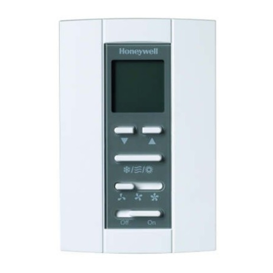
DOWN BUTTON
FAN SWITCH
Display
INDICATES THE
INSTALLER SETUP
INDICATES THE
INSTALLER TEST
KEYPAD LOCK
Lock
Set to
INDICATES THE
SETPOINT
INDICATES THE
TEMPERATURE
CURRENT
MODE
INDICATES TEMPERATURE IS
"CALLING" FOR HEAT OR COOL
UP BUTTON
MODE BUTTON
POWER SWITCH
MCR29502
INDICATES THE NUMBER
OF SETUP OR TEST
Setup
Test
M29503
INSTALLATION INSTRUCTIONS
INSTALLATION GUIDE
CAUTION
Electrical Hazard.
Can cause electrical shock or equipment damage.
Disconnect power before installation.
Terminal Designations
Terminal
L
Line Voltage Power
Ch/Cc
Heating close/Cooling close
W/Y
Heating open/Cooling open
N
Line Voltage Ground
Gl
Low speed fan
Gm
Medium speed fan
Gh
High speed fan
Wiring Diagrams
L
Ch/Cc
W/Y
N
GI
Gm
Gh
Fig. 1. Typical wiring for ON/OFF control in 2 pipes Heat/
Cool/1H1C (for 2-wire valve actuators).
Designation
L
VALVE
N
FAN
M29504
62-0325ES-01
Advertisement
Table of Contents

Related Manuals for Honeywell T6811DP08


Summary of Contents for Honeywell T6811DP08
-
Page 1: Wiring Diagrams
T6811DP08/T6812DP08 Digital Thermostat INSTALLATION INSTRUCTIONS INSTALLATION GUIDE CAUTION Electrical Hazard. DOWN BUTTON UP BUTTON Can cause electrical shock or equipment damage. Disconnect power before installation. FAN SWITCH MODE BUTTON Terminal Designations POWER SWITCH Terminal Designation MCR29502 Line Voltage Power Display... -
Page 2: Installation
T6811DP08/T6812DP08 DIGITAL THERMOSTAT Ch/Cc VALVE M29506 Fig. 3. Wiring thermostat. M29505 4. Align the top of the thermostat with the back cover and Fig. 2. Typical wiring for ON/OFF control in 2 pipes Heat/ push down on the back cover. See Fig. 4, left. -
Page 3: Installer Setup
T6811DP08/T6812DP08 DIGITAL THERMOSTAT Installer Setup 1. Press and hold UP and MODE buttons simultaneously Description Possible Options for 3 seconds to enter the Installer Setup mode. Installer Test Heat 0 Heat Off 2. Press UP or DOWN button to change settings. - Page 4 T6811DP08/T6812DP08 DIGITAL THERMOSTAT Automation and Control Solutions Honeywell International Inc. Honeywell Limited-Honeywell Limitée 1985 Douglas Drive North 35 Dynamic Drive Golden Valley, MN 55422 Toronto, Ontario M1V 4Z9 customer.honeywell.com ® U.S. Registered Trademark © 2009 Honeywell International Inc. 62-0325ES—01 M.S. 10-09...
-
Page 5: Designación De Terminales
Termostato Digital T6811DP08/T6812DP08 INSTRUCCIONES DE INSTALACIÓN Designación de terminales Terminal Descripción Voltaje de línea BOTÓN BOTÓN Ch/Cc Calor cerrado/frío cerrado ABAJO ARRIBA CONMUTADOR BOTÓN Calor abierto/frío abierto DEL VENTILADOR DE MODO Voltaje de línea a tierra Velocidad baja del ventilador... -
Page 6: Instalación De Termostato
TERMOSTATO DIGITAL T6811DP08/T6812DP08 Ch/Cc VÁLVULA VENTILADOR M29506 Fig. 3. Cableado del termostato. MS29505 4. Alinee la parte superior del termóstato con la tapa pos- Fig. 2. Cableado de control típico para prendido/apagado terior y empuje la tapa posterior hacia abajo. Consulte en dos tubos Calor/frío/1H1C (para activadores de válvula... -
Page 7: Configuración Del Instalador
TERMOSTATO DIGITAL T6811DP08/T6812DP08 Configuración del instalador Prueba del instalador 1. Mantenga presionados simultáneamente los botones 1. Mantenga presionados simultáneamente los botones UP (ARRIBA) y MODE (MODO) durante 3 segundos UP (ARRIBA) y DOWN (ABAJO) durante 3 segundos para ingresar al modo Configuración del instalador. -
Page 8: Solución De Problemas
Honeywell International Inc. Honeywell Limited-Honeywell Limitée 1985 Douglas Drive North 35, Dynamic Drive Golden Valley, MN 55422 Toronto, Ontario M1V 4Z9 customer.honeywell.com ® Marca Registrada en los E.U.A © 2009 Honeywell International Inc. todos Los Derechos Reservados 62-0325ES—01 M.S. 10-09...