Advertisement
Quick Links
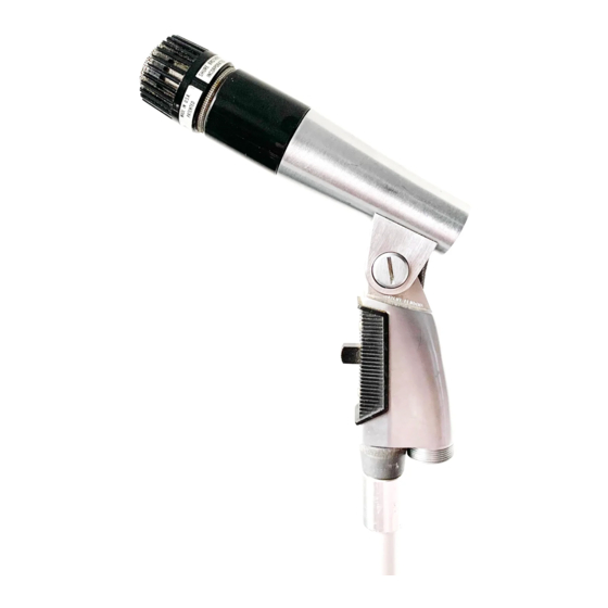
UNIDIRECTIONAL DYNAMIC MICROPHONES
222 HARTREY AVE.. EVANSTON. IL. 60204 U.S.A.
@
AREA CODE 31~/866-zzoo
.
CABLE: SHUREMICRO
TWX: 910-231-0048
TELEX: 72-4381
GENERAL
DATA
MODELS 545 AND 545s
SHEET
UNIDYNEB Ill
The Model 545 Series UNIDYNEO Ill Microphones are
slender dynamic microphones built to provide wide range
reproduction of music and voice, and have an exceptionally
uniform and effective unidirectional pickup pattern.
i
The microphones are particularly suitbLie for high quality
theater-stage
sound systems,
recording,
cathedrals
and
churches, and other critical public address systems such as
those used in political conventions and legislatures, hotels,
stadiums, and public: auditoriums.
Microphone Features:
Unusually effective cardioid pickup pattern that elim-
inates feedback (annoying loudspeaker "squeals") and
prevents echoing (boominess) that sometimes occurs
in partially-filled halls. Can also be used closer to loud-
speakers than usual, without creating feedback problems
Response especially effective for announcing, narration,
vocal and instrumental music
Cartridge shock mounted for quiet operation
A strong detachable cable especially selected for good
shielding from "hum" pickup
Dependability and ruggedness under all operating con-
ditions
The Model 545 Series Microphones are dual impedance
for connection to microphone inputs rated at 19 to 300 ohms
or to high-impedance microphone inputs.
ARCHITECTS' SPECIFICATIONS
The microphone shall be the Shure Model 545 (5453) or
equivalent. The microphone shall be a dynamic (moving coil)
type microphone with a frequency response of 50 to 15,000
Hz. The unit shall have a cardioid polar characteristic. The
cancellation at the sides shall be approximately 6 dB, and
the cancellation at the rear shall be 15 to 20 dB. The micro-
phone shall be a dual-impedance microphone with a rated
impedance of 150 ohms for connection to microphone inputs
rated at 19 to 300 ohms and "High" for connection to high-
impedance
microphone
inputs.
The
microphone
output
shall be:
Low Impedance . . . . . . . . . . . . . . . . . . . . . . . . . . . . . . . . . . . . . . . .
-
57 dB
(0 dB
=
1 milliwatt per 10 microbars)
High Impedance
. . . . . . . . . . . . . . . . . . . . . . . . .
. . .
. . .
. -
55 dB
(0 dB = 1 volt per microbar)
The microphone (Model 545) shall be provided with a
swivel adapter, adjustable through 90" from vertical to
horizontal, and suitable for mounting on a stand having a
%"-27 thread. It shall be provided with a detachable 4.6m
(15 ft) three-conductor shielded cable with a four-pin male
audio connector (equivalent to the Amphenol MC4M con-
nector) at the microphone end. The overall dimensions of
the microphone shall be 148 mm (5-13116 in.) in length and
31.8 mm (1%
in.)
in diameter.
The microphone (Model 5453) shall be provided with a
swivel, and a built-in On-Off switch. It shall also be provided
with a detachable 4.6m (15 ft) three-conductor shielded cable
with a four-pin male audio connector (equivalent to the
Amphenol MC4M connector) at the microphone end. The
overall dimensions of the microphone shall be 122.2 mm
(4-13116 in.) in height, 31.8 mm (1% in.) in width and 148 mm
(5-13116 in.) in depth.
IMPEDANCE SELECTION
Either high- or low-impedance operation of these micro-
phones is selected by the leads chosen for connection at
the equipment end of the microphone cable. For high
impedance, the RED lead is the "hot" conductor; the shield
is connected to the
amplifier or chassis ground. For
balanced-line low im~edance, the BLACK and WHITE leads
are the "hot"
conductors; the shield is connected to the
amplifier or chassis ground. For unbalanced low impedance,
the WHITE lead is the "hot" conductor with the BLACK lead
and shield connected together to the amplifier or chassis
ground. Any leads not being used for a particular connection
should be insulated at the equipment end of the cable.
The low-impedance connection is recommended where
long cable lengths are required or under conditions of
severe hum disturbance. The permissible cable length is
practically unlimited, since neither response nor level is
appreciably affected. For use with high-impedance amplifiers,
the Shure Model A95 Series Line Matching Transformers are
available for coupling a low-impedance line to the amplifier
input. The Model A95 Series transformers permit coupling a
19-300 ohm microphone line to a high-impedance input.
Copyright 1978. Shure Brothers Inc.
27A443 (RC)
(OVER)
Important:
Shure Microphone Cables are selected after ex-
haustive tests to insure superior performance in microphones
because of low capacities, superior shielding properties and
unusually long life under severe use.
Cables with plastic insulation should not be subjected to
excessive soldering-iron heat. Carefully clean and tin the
conductors and the connections to which the conductors
are to be soldered. The soldering operation can then be
done with a minimum of heat, thereby avoiding any pos-
sibility of damage to the cable.
U.S.
Patents 3,132,713, 3,240,883 and D190,864
Printed
i n
U.S.A.
Advertisement

Related Manuals for Shure 545 UNIDYNE III


Summary of Contents for Shure 545 UNIDYNE III
- Page 1 For unbalanced low impedance, the WHITE lead is the "hot" conductor with the BLACK lead The microphone shall be the Shure Model 545 (5453) or and shield connected together to the amplifier or chassis equivalent. The microphone shall be a dynamic (moving coil) ground.
- Page 2 CASEOROUND ASSEMBLY C A R T R ~ E GROW This Shure product is guaranteed in normal use to be free MODEL 545 from electrical and mechanical defects for a period of one year from date of purchase. Please retain proof of purchase TRANSFWYER?.,...