
Related Manuals for Aiphone GHW-LC


Summary of Contents for Aiphone GHW-LC
- Page 1 0207 GHW-LC GH System Lift control adaptor GHW-LC INSTALLATION & OPERATION MANUAL - 1 -...
-
Page 2: Table Of Contents
Specifications 4. For DC powered systems, use Aiphone power supply model specified with system. If non-specified product is used, fire or malfunction could result. 5. Do not install the unit in any of the following locations. Fire, electric shock, or unit trouble could result. -
Page 3: Wiring Distance
Installation & Operation Manual.) Make sure to use GH-BCX/A, GH-DA/A, GH-NS. [1] Expanded Bus control unit GH-BCX/A [2] Distribution terminal (junction): Not included [3] Lift control adaptor GHW-LC GHW-LC Relay contacts: 20 [4] Bus control unit GH-BC [5] Power supply PS-2410LC, PS-2410LD, PS-2410DIN... -
Page 4: Contents
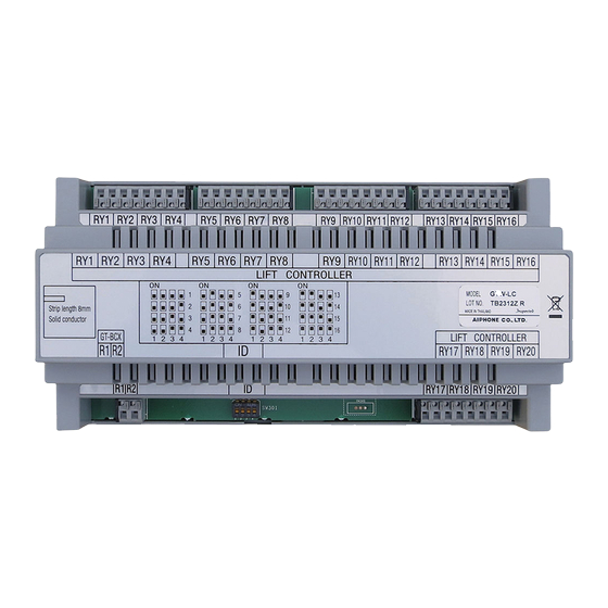
CONTENTS NAMES GHW-LC Contents Lift control adaptor GHW-LC (mounting bracket is included) Names [1] Bus line terminal [2] ID setting switch [3] Relay output terminal [4] Lock release lever - 4 -... -
Page 5: Mounting
MOUNTING GHW-LC Mounting [1] Din rail [2] Lock release lever Mount GHW-LC to the Din rail. ∗ To remove GHW-LC, pull the lock release lever down. GHW-LC cannot be mounted directly to the wall surface. - 5 -... -
Page 6: Wiring
WIRING GH-BCX/A GHW-LC RY20 Max. 8 Lift controller #9 to #16 GH-BCX/A (max. 8) GHW-LC RY20 GHW-LC 1 2 3 4 1 2 3 4 1 2 3 4 1 2 3 4 1 2 3 4 1 2 3 4... - Page 7 Installation & Operation Manual.) [1] Expanded Bus control unit GH-BCX/A [2] Distribution terminal (junction): Not included [3] Lift control adaptor GHW-LC Maximum 16 adaptors (up to 8 adaptors per trunk) • ID: ID setting switch (factory setting is #1) Make sure to set corresponding ID number.
-
Page 8: Setting Up
Setup tool SETTING UP ∗ Completing settings with the setup tool is required. 1. Install the setup tool in the PC (Windows XP/2000/ME ®) beforehand, and then enter the resident information. ∗ For details on the setup tool, refer to the GH Series Installation &... -
Page 9: Lift Control 1
[1] The resident information that has been entered will be Lift Control 1 displayed. [2] Set which relay will activate in the corresponding GHW-LC [1] GHW-LC ID for each residence. The setting range is "1 to 20". [2] Select "ON" or "OFF" for the GHW-LC connection. -
Page 10: Combine Data
OPERATIONS Residential Station or Security Guard Station Door Release 1. Press the door release button at the residential station or security guard station while in communication with the entrance station that made a call. 2. The door release function will activate on the entrance station that is in communication, and the lift will begin to move. -
Page 11: Technical Precautions
TECHNICAL PRECAUTIONS SPECIFICATIONS Technical precautions Specifications • Operating temperature: 0 °C to 40 °C (32 °F to 104 °F) • Power supply: Supplied by GH-BC • Repair requests: When units do not operate properly, contact a • Relay contacts: 20 qualified technician for service. - Page 12 Aiphone product which has been subject to misuse, measures: • Reorient or relocate the receiving antenna • Connect the equipment into an neglect, accident, or to use in violation of instructions furnished, nor extended to units outlet on a circuit different from that to which the receiver is connected.
Need help?
Do you have a question about the GHW-LC and is the answer not in the manual?
Questions and answers