
Subscribe to Our Youtube Channel
Related Manuals for YOKOGAWA Power Series Plus IM 2493WVP-1


Summary of Contents for YOKOGAWA Power Series Plus IM 2493WVP-1
- Page 1 Plus Users Power Series Manual Plus Power Series Watt / VAR / Power Factor Digital Switchboard Meter IM 2493WVP-1 IM 2493WVP-1 Revision 1, October 1999...
-
Page 2: Table Of Contents
Changing the rolling average setting .............11 Changing the network address setting............12 Changing the baud rate setting..............12 Analog Output Scaling ...................13 Changing the Analog Output Settings............14 Connection Diagrams ....................19 Mounting and Outline..................22 IM 2493WVP-1 edition, October 1999 All Rights Reserved, Copyright 1999, Yokogawa Corporation of America... -
Page 3: General Description
1. GENERAL DESCRIPTION 1. GENERAL DESCRIPTION The Yokogawa Corporation of America POWER SERIES Plus digital switchboard meters incorporate the latest DSP ASIC technology. The ASIC circuitry, developed by Yokogawa, has created a family of user-friendly, field-adjustable meters. When ordering the 2493 meter, the following options are available: AC Measuring Function(s): Volts, Amps, Watts, VARs, Power Factor, and/or Frequency. - Page 4 1. GENERAL DESCRIPTION operation and maintenance of the Equipment, or normal wear and tear on disposable or consumable parts. This warranty shall be void in the event of unauthorized modification or servicing of the Equipment. The foregoing warranty is exclusive and in lieu of any other warranties of quality, whether expressed or implied (including any warranty of merchantability or fitness for a particular purpose).
-
Page 5: Specifications
2. SPECIFICATIONS 2. SPECIFICATIONS PRODUCT FUNCTION: AC Watts/VARs/Power Factor 1 phase-2 wire, 1 phase-3 wire, 3 phase-3 wire, 3 phase-4 wire-2½ elements or 3 phase- 4 wire-3 elements ACCURACY: Watts & VARs : 0.2% of Reading 0.1% of Full Scale Power Factor: 0.05 DISPLAY UPDATE RATE:... - Page 6 2. SPECIFICATIONS ISOLATION: Input/Output and Case: 2500 VAC Output to Aux. Power: 2000 VAC or 500 VDC for DC powered options Aux. Power to Case: 2000 VAC or 500 VDC for DC powered options Output to Case: 1000 VAC IM 2493WVP-1...
-
Page 7: Configuration
3. CONFIGURATION 3. CONFIGURATION Plus Configuring the 2493 POWER SERIES Meter Plus The new triple-display POWER SERIES can be configured for voltage and current inputs from instrument transformers, as well as analog outputs, RS-485 network address and a rolling average display. All set-up functions can be performed using the four push-buttons on the front panel (see below) or via RS-485 communications. - Page 8 3. CONFIGURATION following pages for details on how to change the settings. Once a setting is changed it will advance to the next setting. At any point while changing settings, pressing Mode will exit the mode without changing anything. IM 2493WVP-1...
-
Page 9: Keymap
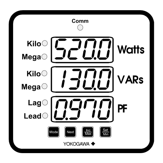
4. KEYMAP 4. KEYMAP Plus This flowchart illustrates the operation of the POWER SERIES meter using the push-keys on the front panel. This flowchart depicts the front panel key options when operating in normal reading mode. The options are: Mode-Mode – Invokes change setting menu (see flow chart page 8). Mode –... -
Page 10: Changing Settings
5. CHANGING SETTINGS 5. CHANGING SETTINGS Note: This flowchart gives information pertaining to units equipped with YCA communications or no communications option. The setup flow is slightly different for units with MODBUS communications. See the Power Series communications manual (IM 249x-COMM) for details. -
Page 11: Changing The Potential Transformer (Pt) Ratio Setting
5. CHANGING SETTINGS Changing the Potential Transformer (pt) ratio setting When you reach the PT setting, the primary value will be displayed in the middle row and the secondary value will be displayed in the bottom row. Press Set and the first digit of the primary value will begin blinking. -
Page 12: Changing The Current Transformer (Ct) Ratio Setting
5. CHANGING SETTINGS the combined ratio of CT * PT cannot exceed 357910. This is the mathematical limit to the software. You will get “ErrH” or ErrL” if you try to advance to Confirm mode with an incorrect ratio. If you try to save a ratio value that exceeds the precision of the unit, that value will be automatically rounded off. -
Page 13: Changing The Rolling Average Setting
5. CHANGING SETTINGS If you have a 5 Amp unit, the next time you press Set the value of the secondary will blink. To change the value, press Inc. There are only two choices: 1 or 5. If you have a 1 Amp unit, or you have set the secondary on a 5 Amp unit, pressing Set will now move you to the Confirm mode. -
Page 14: Changing The Network Address Setting
5. CHANGING SETTINGS When you reach the Average setting, press Set and the first digit will begin blinking. To increment the value of the digit, press Inc. Once a digit has reached 9 (nine), it will then go to 0 (zero). To move to the second digit press Next. To return to the first digit press Next again. -
Page 15: Analog Output Scaling
5. CHANGING SETTINGS Analog Output Scaling Plus The POWER SERIES has the option of analog output, which can provide an analog signal relative to the input of the meter. The relationship between the input and the output can be scaled by the user using the front panel. Analog Output 1 is always proportional to the value shown on the top display (Watts). -
Page 16: Changing The Analog Output Settings
5. CHANGING SETTINGS A unit with 1mA output can be configured by the user to range from 0 to 1 mA or from –1 to 1 mA. This setting is referred to as CEN (short for ‘center’) on the front panel display. If the unit is set to 0-1 mA it is guaranteed never to have an output below 0 mA, regardless of the input. - Page 17 5. CHANGING SETTINGS Changing the HI value is done in the same manner as changing the primary for PT or CT. First the digits, then the decimal point, then the multipliers (Kilo/Mega), and finally confirm the new setting. After pressing Set to confirm the new setting, the LO1 value will be displayed. To enable you to set either a negative or positive value for LO1 there is a “sign dash”.
- Page 18 5. CHANGING SETTINGS OUT3: There is no multiplier for Out3 (Power Factor). The first digit only toggles between ‘0’ and ‘1’. The decimal point cannot be changed. Note that the output settings have a precision of four (4) digits only. When the PT or CT ratio is large, this will result in rounding if you try to set a value too precisely.
- Page 19 5. CHANGING SETTINGS Plus The following values apply to the POWER SERIES Watt-VAR-PF meters: For Output 1 (Watts): Input Defaults Span Minimum Maximum Minimum 2Wire 120V 1A 100.0 -180.0 180.0 50.00 2Wire 240V 1A 200.0 -360.0 360.0 100.0 2Wire 120V 5A 500.0 -900.0 900.0...
- Page 20 5. CHANGING SETTINGS For Output 3 (Power Factor): Input Defaults Range Limits Span Minimum All 0-1 mA units 1.000 0.000 0.000 Lag – 1 – 0.000 0.250 Lead Lead All 4-20 mA 0.000 0.000 0.000 Lag – 1 – 0.000 0.250 units Lead...
-
Page 21: Connection Diagrams
6. CONNECTION DIAGRAMS 6. CONNECTION DIAGRAMS Connection Diagrams – Part 1 WARNING: All circuits should be de-energized when making connections to the rear terminal block. IM 2493WVP-1... - Page 22 6. CONNECTION DIAGRAMS Connection Diagrams – Part 2 WARNING: All circuits should be de-energized when making connections to the rear terminal block. IM 2493WVP-1...
- Page 23 6. CONNECTION DIAGRAMS Connection Diagrams – Part 3 All circuits should be de-energized when making connections to the rear terminal block. IM 2493WVP-1...
-
Page 24: Mounting And Outline
6. CONNECTION DIAGRAMS Mounting and Outline IM 2493WVP-1...
Need help?
Do you have a question about the Power Series Plus IM 2493WVP-1 and is the answer not in the manual?
Questions and answers