Mitsubishi Electric PAR-30MAA Installation Manual
City multi control system and mitsubishi mr. slim air conditioners
Hide thumbs
Also See for PAR-30MAA:
- Technical manual (100 pages) ,
- Instruction book (56 pages) ,
- Installation manual (17 pages)
Table of Contents
Advertisement
Available languages
Available languages
CITY MULTI Control System
and Mitsubishi Mr. SLIM Air Conditioners
MA Remote Controller
Installation Manual
This installation manual describes how to install the MA Remote Controller for use with Mitsubishi Building Air Conditioning System, direct
expansion type CITY MULTI air conditioner indoor units (“-A” type and later), and Mitsubishi Mr. SLIM packaged air conditioners.
Please be sure to read this installation manual and the files on the CD-ROM that is supplied with the Remote Controller before proceeding
with the installation. Failure to follow the instructions may result in equipment damage.
For information not contained in this booklet, please refer to the files on the CD-ROM that is supplied with the Remote Controller.
If the files are not readable, please contact your dealer.
For information on how to wire and install the air conditioning units, refer to the installation manual.
After the installation, hand over this manual to users.
1. Safety Precautions
• Thoroughly read the following safety precautions prior to installation.
• Observe these precautions carefully to ensure safety.
WARNING
Indicates a risk of death or serious injury.
CAUTION
Indicates a risk of serious injury or structural damage.
• After reading this manual, pass it on to the end user to retain for future reference.
• Keep this manual for future reference and refer to it as necessary. This manual should be made available to those who repair or relocate
the controller. Make sure that the manual is passed on to any future users.
General precautions
WARNING
Do not install the unit in a place where large amounts of oil, steam,
organic solvents, or corrosive gases, such as sulfuric gas, are present
or where acidic/alkaline solutions or sprays are used frequently. These
substances can compromise the performance of the unit or cause
certain components of the unit to corrode, which can result in electric
shock, malfunctions, smoke, or fire.
To reduce the risk of shorting, current leakage, electric shock,
malfunctions, smoke, or fire, do not wash the controller with water
or any other liquid.
To reduce the risk of electric shock, malfunctions, smoke or fire, do
not operate the switches/buttons or touch other electrical parts with
wet hands.
CAUTION
To reduce the risk of fire or explosion, do not place flammable
materials or use flammable sprays around the controller.
To reduce the risk of damage to the controller, do not directly spray
insecticide or other flammable sprays on the controller.
To reduce the risk of electric shock or malfunctions, do not touch
the touch panel, switches, or buttons with a pointy or sharp object.
PAR-30MAA
All electric work must be performed by qualified personnel.
For distribution to dealers and contractors
To reduce the risk of injury or electric shock, before spraying a
chemical around the controller, stop the operation and cover the
controller.
To reduce the risk of injury or electric shock, stop the operation and
switch off the power supply before cleaning, maintaining, or inspecting
the controller.
Properly install all required covers to keep moisture and dust out of the
controller. Dust accumulation and water can cause electric shock,
smoke, or fire.
To reduce the risk of injury, keep children away while installing,
inspecting, or repairing the controller.
To reduce the risk of injury and electric shock, avoid contact with
sharp edges of certain parts.
To avoid injury from broken glass, do not apply excessive force on the
glass parts.
To reduce the risk of injury, wear protective gear when working on the
controller.
– 1 –
WT05950X01_
GB
Advertisement
Table of Contents

Related Manuals for Mitsubishi Electric PAR-30MAA


Summary of Contents for Mitsubishi Electric PAR-30MAA
-
Page 1: Installation Manual
For distribution to dealers and contractors This installation manual describes how to install the MA Remote Controller for use with Mitsubishi Building Air Conditioning System, direct expansion type CITY MULTI air conditioner indoor units (“-A” type and later), and Mitsubishi Mr. SLIM packaged air conditioners. - Page 2 This controller is designed for exclusive use with the Building To avoid damage to the controller, do not overtighten the screws. Management System by Mitsubishi Electric. The use of this controller for with other systems or for other purposes may cause malfunctions.
-
Page 3: System Requirements
To avoid damage to the controller, provide protection against static Do not install the controller on the control panel door. electricity. Vibrations or shocks to the controller may damage the controller or cause the controller to fall. Do not use solderless terminals to connect cables to the terminal block. -
Page 4: Selecting An Installation Site
4. Field-supplied parts/Required tools (1) Field-supplied parts The following parts are field-supplied parts. Parts name Qty. Notes Double switch box Thin metal conduit Necessary Not required for direct wall installation Lock nut and bushing Necessary Cable cover Necessary Required for routing remote controller cable along a wall Putty Reasonable Molly anchor... - Page 5 6. Installation/Wiring work (1) Installation work Controller can be installed either in the switch box or directly on the wall. Perform the installation properly according to the method. Conduit Wall Drill a hole in the wall. tube ■ Installation using a switch box Locknut •...
- Page 6 Install the bottom case. ■ Installation using a switch box • Secure at least two corners of the switch box with screws. ■ Direct wall installation • Thread the cable through the groove. • Secure at least two corners of the remote controller with screws. •...
- Page 7 Route the wire to the top case. Important Hold the cables in place with clamps to prevent undue force from being applied to the terminal block and causing cable breakage. Clamp Insert the wire. Install the front cover and top case on the bottom case. Two mounting tabs are at the top of the top case.
- Page 8 Important Use a flat-head screwdriver with a blade width of 4-7 mm (5/32-9/ To prevent damage to the control board, do not insert the driver 32 inch). The use of a screwdriver with a narrower or wider blade into the slot strongly. tip may damage the controller casing.
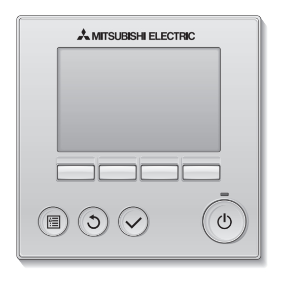
- Page 9 8. Remote controller button functions (7) Backlit LCD (2) Function buttons F1, F2, F3, and F4 from the left (6) Operation indicator (1) ON/OFF button (4) RETURN button (3) MENU button (5) SELECT button Pressing the MENU button will bring up the Main menu as shown below.
-
Page 10: Turning On The Power
9. Turning on the power Make sure that the MA remote controller is properly installed according to the instructions in the Installation Manual and that the indoor and outdoor unit installation has been completed before turning on the power. (1) When the power is turned on, the following screen will appear. Notes ·... - Page 11 (2) Clock setting [Button operation] Clock [1] Move the cursor with the F1 or F2 button to the desired item. yyyy/ mm/ dd hh: mm [2] Change the date and time with the F3 or F4 button, and press the SELECT button to save the 2010/ 01/ 01 12: 00 change.
- Page 12 [3]Room temperature display [Button operation] Move the cursor to the “Room temp.” on the display details setting screen, and select the desired setting with the F3 or F4 button. (The factory setting is “Yes”.) · Yes: Room temperature appears on the Main display. ·...
- Page 13 12. Service menu (Maintenance password is required.) At the Main display, press the MENU button and select “Service” to make the maintenance settings. When the Service menu is selected, a window will appear asking for the password. To enter the current maintenance password (4 numerical digits), move the cursor to the digit you want to change with the F1 or F2 button, and set each number (0 through 9) with the F3 or F4 button.
- Page 14 [3] Use the F1 or F2 button to move [4] When the settings are completed, Function setting Function setting the cursor to select the mode press the SELECT button to send Ref. address Unt # 1 Ref. address Grp. Mode 7 number, and change the setting the setting data from the remote Mode 8...
- Page 15 To search for the LOSSNAY address [4] Enter the address of the indoor unit to which the remote controller is Lossnay Lossnay connected, select "Conf" in the "Function", and press the SELECT button. IU address IU address Lossnay address Lossnay address "Collecting data"...
-
Page 16: Remote Controller Check
[2] If the SELECT button is pressed after the remote controller check results are displayed, remote controller check will end, and the remote controller will automatically reboot itself. HEAD OFFICE: TOKYO BLDG., 2-7-3, MARUNOUCHI, CHIYODA-KU, TOKYO 100-8310, JAPAN Authorized representative in EU: MITSUBISHI ELECTRIC EUROPE B.V. HARMAN HOUSE, 1 GEORGE STAREET, UXBRIDGE, MIDDLESEX UB8 1QQ, U.K. – 16 –... - Page 17 Zur Verteilung an Händler und Lieferanten Diese Installationsanleitung beschreibt das Installieren der MA-Fernsteuerung zur Verwendung mit Gebäude-Klimagerätesystemen von Mitsubishi, dem direkten Erweiterungstyp der Klimaanlagen-Innengeräte CITY MULTI (Typ A und später) und den Kompaktklimageräten Mr. Slim von Mitsubishi. Lesen Sie vor dem Installationsbeginn die Installationsanleitung und die Dateien auf der CD-ROM, die der Fernsteuerung beiliegt. Eine Nichtbeachtung der Anweisungen könnte zu Schäden der Ausrüstung führen.
- Page 18 Um Schäden an der Steuerung zu vermeiden, dürfen die Schrauben nicht zu Diese Steuerung ist ausschließlich für die Verwendung mit dem fest angezogen werden. Gebäudeverwaltungssystem von Mitsubishi Electric konzipiert. Die Verwendung dieser Steuerung mit anderen Systemen oder zu anderen Zwecken könnte zu Fehlfunktionen führen.
- Page 19 Um Schaden an der Steuerung zu vermeiden, muss das Gerät gegen Die Steuerung darf nicht an der Tür der Steuertafel angebracht werden. statische Elektrizität geschützt werden. Durch Vibrationen oder Stöße konnte die Steuerung beschädigt werden oder herunterfallen. Verwenden Sie zum Anschluss der Kabel an den Anschlussblock keine lötfreien Verbindungen.
-
Page 20: Auswahl Des Installationsortes
4. Vor Ort zu beschaffende Teile/Notwendige Werkzeuge (1) Vor Ort zu beschaffende Teile Die folgenden Teile sind vor Ort zu beschaffen: Teilebezeichung Anzahl Hinweise Doppelter Schaltkasten Dünner Metallschlauch Notwendig Für Wandinstallation nicht notwendig Sicherungsmuttern und Durchführungshülsen Notwendig Zum Führen des Fernsteuerungskabels entlang Kabelmantel Notwendig einer Wand notwendig... - Page 21 6. Installation/Verkabelung (1) Installationsarbeiten Die Steuerung kann entweder in einem Schaltkasten oder direkt an einer Wand montiert werden. Führen Sie die Installation entsprechend den Anweisungen aus. Wand Bohren Sie ein Loch in die Wand. Kabelrohr ■ Installation mithilfe eines Schaltkastens Sicherungsmutter •...
- Page 22 Befestigen Sie das Untergehäuse. ■ Installation mithilfe eines Schaltkastens • Verschrauben Sie mindestens zwei Ecken des Schaltkastens. ■ Wandinstallation • Führen Sie das Kabel durch die Nute. • Verschrauben Sie mindestens zwei Ecken der Fernsteuerung. • Die linke obere und die rechte untere Kante der Fernsteuerung (von der Vorderseite aus betrachtet) müssen sicher befestigt werden, um ein Abheben zu vermeiden.
- Page 23 Führen Sie das Kabel zum Obergehäuse. Wichtig Halten Sie die Kabel mit Klemmen in Position, um zu verhindern, dass zuviel Zugspannung am Anschlussblock anliegt und die Kabel Kabelklemme dadurch beschädigt werden. Kabel durchführen. Bringen Sie die vordere Abdeckung und das Obergehäuse am Untergehäuse an. Es befinden sich zwei Befestigungszungen oben am Obergehäuse.
- Page 24 Wichtig Verwenden Sie einen Flachkopfschraubendreher mit eine Um Schaden an der Steuerplatine zu vermeiden, muss der Klingenbreite von 4-7 mm (5/32-9/32 Zoll). Die Verwendung eines Schraubendreher vorsichtig in den Spalt eingeführt werden. Schraubendrehers mit einer schmaleren oder breiteren Klinge könnte das Steuerungsgehäuse beschädigen. Um Schaden am Steuerungsgehäuse zu vermeiden, darf der Schraubendreher nicht mit Gewalt im Schlitz gedreht werden.
-
Page 25: Tastenfunktionen Der Fernbedienung
8. Tastenfunktionen der Fernbedienung (7) LCD mit Hintergrundbeleuchtung (2) Funktionstasten F1, F2, F3 und F4 von links nach rechts (6) Betriebsanzeige (1) EIN/AUS-Taste (4) ZURÜCK-Taste (3) MENÜ-Taste (5) AUSWAHL-Taste Durch Drücken der MENÜ-Taste wird das Hauptmenü angezeigt, wie unten abgebildet. (1) EIN/AUS-Taste (Siehe Abschnitt 9.(2) „Hauptdisplay“... -
Page 26: Einschalten Der Stromversorgung
9. Einschalten der Stromversorgung Vergewissern Sie sich, dass die MA-Fernbedienung ordnungsgemäß entsprechend den Anleitungen im Installationshandbuch installiert worden ist und dass die Innen- und Außengeräteinstallation abgeschlossen ist, bevor Sie die Stromversorgung einschalten. (1) Beim Einschalten der Stromversorgung wird der folgende Bildschirm angezeigt. Hinweise ·... - Page 27 (2) Uhreinstellung [Tastenbedienung] [1] Bewegen Sie die Marke mit Hilfe der F1- oder F2-Taste zur gewünschten Option. [2] Ändern Sie das Datum und die Uhrzeit mit Hilfe der F3- oder F4-Taste und drücken Sie die JJJJ/ MM/ TT hh: mm AUSWAHL-Taste, um die Änderung zu speichern.
- Page 28 [3]Raumtemperaturanzeige [Tastenbedienung] Bewegen Sie die Marke im Bildschirm zum Einstellen der Displaydetails zur Option „Raumtemp.“ und wählen Sie die gewünschte Einstellung mit Hilfe der F3- oder F4-Taste aus. (Die Werkseinstellung ist „Ja“.) · Ja: Die Raumtemperatur wird im Hauptdisplay angezeigt. ·...
- Page 29 12. Service-Menü (Wartungspasswort ist erforderlich.) Drücken Sie im Hauptdisplay die MENÜ-Taste und wählen Sie dann „Service“ aus, um die Wartungseinstellungen vorzunehmen. Bei der Auswahl des Service-Menüs wird ein Fenster geöffnet, das zur Passworteingabe auffordert. Zur Eingabe des aktuellen Wartungspassworts (4 Ziffern) bewegen Sie die Marke mit Hilfe der F1- oder F2-Taste zu der Ziffer, die Sie ändern möchten, und stellen dann den gewünschten Wert (0 bis 9) jeweils mit Hilfe der F3- oder F4-Taste ein.
- Page 30 [3] Bewegen Sie die Marke mit Hilfe der [4] Wenn Sie alle Einstellungen Funktionseinstellungen Funktionseinstellungen F1- oder F2-Taste zur gewünschten vorgenommen haben, drücken Sie die Ref.-Adresse Geräte# 1 Ref.-Adresse Grp. Mod. 7 Betriebsartnummer und ändern Sie AUSWAHL-Taste, um die Einstellungen Mod.
- Page 31 Zum Suchen einer LOSSNAY-Adresse [4] Geben Sie die Adresse des Innengeräts ein, an das die Fernbedienung Lossnay Lossnay angeschlossen ist, wählen Sie „Best“ unter der „Funktion“ und drücken Sie Adresse IG Adresse IG die AUSWAHL-Taste. Auf dem Bildschirm wird „Daten werden geladen“ Adresse Lossnay Adresse Lossnay angezeigt.
- Page 32 Fernbedienungsprüfung beendet und die Fernbedienung führt automatisch einen Neustart durch. HEAD OFFICE: TOKYO BLDG., 2-7-3, MARUNOUCHI, CHIYODA-KU, TOKYO 100-8310, JAPAN Autorisierte Vertretungsstelle in der EU: MITSUBISHI ELECTRIC EUROPE B.V. HARMAN HOUSE, 1 GEORGE STREET, UXBRIDGE, MIDDLESEX UB8 1QQ, U.K. – 16 –...