Mitsubishi Electric Melservo-J3 Series MR-J3-B Instruction Manual
Melservo j3 series general-purpose ac servo sscnet compatible
Hide thumbs
Also See for Melservo-J3 Series MR-J3-B:
- Instruction manual (802 pages) ,
- Manual (668 pages) ,
- Handbook (590 pages)

Related Manuals for Mitsubishi Electric Melservo-J3 Series MR-J3-B


Summary of Contents for Mitsubishi Electric Melservo-J3 Series MR-J3-B
- Page 1 General-Purpose AC Servo Series SSCNET Compatible MODEL MR-J3- B SERVO AMPLIFIER INSTRUCTION MANUAL...
-
Page 2: Safety Instructions
Safety Instructions (Always read these instructions before using the equipment.) Do not attempt to install, operate, maintain or inspect the servo amplifier and servo motor until you have read through this Instruction Manual, Installation guide, Servo motor Instruction Manual and appended documents carefully and can use the equipment correctly. - Page 3 1. To prevent electric shock, note the following: WARNING Before wiring or inspection, turn off the power and wait for 15 minutes or more (20 minutes or for drive unit 30kW or more) until the charge lamp turns off. Then, confirm that the voltage between P( ) and N( ) (L and L for drive unit 30kW or more) is safe with a voltage tester and others.
- Page 4 4. Additional instructions The following instructions should also be fully noted. Incorrect handling may cause a fault, injury, electric shock, etc. (1) Transportation and installation CAUTION Transport the products correctly according to their weights. Stacking in excess of the specified number of products is not allowed. Do not carry the servo motor by the cables, shaft or encoder.
- Page 5 Never hit the servo motor or shaft, especially when coupling the servo motor to the machine. The encoder may become faulty. Do not subject the servo motor shaft to more than the permissible load. Otherwise, the shaft may break. When the equipment has been stored for an extended period of time, consult Mitsubishi. (2) Wiring CAUTION Wire the equipment correctly and securely.
- Page 6 (3) Test run adjustment CAUTION Before operation, check the parameter settings. Improper settings may cause some machines to perform unexpected operation. The parameter settings must not be changed excessively. Operation will be insatiable. (4) Usage CAUTION Provide an external emergency stop circuit to ensure that operation can be stopped and power switched off immediately.
- Page 7 (5) Corrective actions CAUTION When it is assumed that a hazardous condition may take place at the occur due to a power failure or a product fault, use a servo motor with electromagnetic brake or an external brake mechanism for the purpose of prevention.
- Page 8 Write to the EEP-ROM due to device changes Precautions for Choosing the Products Mitsubishi will not be held liable for damage caused by factors found not to be the cause of Mitsubishi; machine damage or lost profits caused by faults in the Mitsubishi products; damage, secondary damage, accident compensation caused by special factors unpredictable by Mitsubishi;...
- Page 9 COMPLIANCE WITH EC DIRECTIVES 1. WHAT ARE EC DIRECTIVES? The EC directives were issued to standardize the regulations of the EU countries and ensure smooth distribution of safety-guaranteed products. In the EU countries, the machinery directive (effective in January, 1995), EMC directive (effective in January, 1996) and low voltage directive (effective in January, 1997) of the EC directives require that products to be sold should meet their fundamental safety requirements and carry the CE marks (CE marking).
- Page 10 (2) Configuration The control circuit provide safe separation to the main circuit in the converter unit and servo amplifier (drive unit). (a) MR-J3-22KB(4) or less Control box Reinforced insulating type 24VDC power supply No-fuse Magnetic Serve breaker contactor motor Servo amplifier (b) MR-J3-DU30KB(4) or more Control box...
- Page 11 (b) Do not connect two ground cables to the same protective earth (PE) terminal. Always connect the cables to the terminals one-to-one. PE terminals PE terminals (c) If a leakage current breaker is used to prevent an electric shock, the protective earth (PE) terminals of the servo amplifier must be connected to the corresponding earth terminals.
- Page 12 CONFORMANCE WITH UL/C-UL STANDARD (1) Converter unit, servo amplifiers (drive unit) and servo motors used Use the converter unit, servo amplifiers (drive unit) and servo motors which comply with the standard model. Converter unit series :MR-J3-CR55K MR-J3-CR55K4 Servo amplifier (drive unit) series :MR-J3-10B to MR-J3-22KB MR-J3-10B1 to MR-J3-40B1 MR-J3-60B4 to MR-J3-22KB4...
- Page 13 (4) Capacitor discharge time The capacitor discharge time is as listed below. To ensure safety, do not touch the charging section for 15 minutes (more than 20 minutes in case drive unit is 30kW or more) after power-off. Servo amplifier Discharge time [min] MR-J3-10B 20B MR-J3-40B 60B(4) 10B1 20B1...
- Page 14 (7) About wiring protection For installation in United States, branch circuit protection must be provided, in accordance with the National Electrical Code and any applicable local codes. For installation in Canada, branch circuit protection must be provided, in accordance with the Canada Electrical Code and any applicable provincial codes.
- Page 15 MEMO A - 14...
-
Page 16: Table Of Contents
CONTENTS 1. FUNCTIONS AND CONFIGURATION 1 - 1 to 1 -28 1.1 Introduction............................... 1 - 1 1.2 Function block diagram..........................1 - 2 1.3 Servo amplifier standard specifications....................1 - 5 1.4 Function list .............................. 1 - 7 1.5 Model code definition ..........................1 - 8 1.6 Combination with servo motor ........................ - Page 17 3.13 Control axis selection..........................3 -51 4. STARTUP 4 - 1 to 4 -10 4.1 Switching power on for the first time ....................... 4 - 1 4.1.1 Startup procedure..........................4 - 1 4.1.2 Wiring check ............................4 - 2 4.1.3 Surrounding environment........................4 - 3 4.2 Start up ..............................
- Page 18 6.4 Interpolation mode ..........................6 -11 6.5 Differences between MELSERVO-J2-Super and MELSERVO-J3 in auto tuning........ 6 -12 7. SPECIAL ADJUSTMENT FUNCTIONS 7 - 1 to 7 -16 7.1 Function block diagram..........................7 - 1 7.2 Adaptive filter ............................7 - 1 7.3 Machine resonance suppression filter.....................
- Page 19 11.3.4 Outline dimension drawings......................11-43 11.4 Power regeneration converter ......................11-45 11.5 Power regeneration common converter ....................11-48 11.6 External dynamic brake ........................11-56 11.7 Junction terminal block PS7DW-20V14B-F (recommended)............. 11-61 11.8 MR Configurator........................... 11-63 11.9 Battery MR-J3BAT ..........................11-64 11.10 Heat sink outside mounting attachment (MR-J3ACN)..............
- Page 20 13.4.1 Display flowchart ........................... 13-47 13.4.2 Status display mode........................13-48 13.4.3 Diagnostic mode..........................13-49 13.4.4 Alarm mode ........................... 13-51 13.4.5 Parameter mode ........................... 13-52 13.5. Parameters for converter unit ......................13-53 13.5.1 Parameter list ..........................13-53 13.5.2 List of details..........................13-54 13.6 Troubleshooting ...........................
- Page 21 MEMO...
-
Page 22: Functions And Configuration
1. FUNCTIONS AND CONFIGURATION 1.1 Introduction The Mitsubishi MELSERVO-J3 series general-purpose AC servo has further higher performance and higher functions compared to the current MELSERVO-J2-Super series. The MR-J3-B servo amplifier connects to servo system controller and others via high speed synchronous network and operates by directly reading position data. -
Page 23: Function Block Diagram
1. FUNCTIONS AND CONFIGURATION 1.2 Function block diagram The function block diagram of this servo is shown below. (1) MR-J3-350B or less MR-J3-200B4 or less Power factor improving DC Regenerative reactor option N( ) Servo amplifier P( ) Servo motor Diode (Note 1) stack Relay... - Page 24 1. FUNCTIONS AND CONFIGURATION (2) MR-J3-350B4 MR-J3-500B(4) MR-J3-700B(4) Power factor improving DC Regenerative reactor option Servo amplifier Servo motor Diode stack Relay (Note) Current Power detector supply CHARGE Regene- lamp rative Dynamic Cooling fan brake Electro- Control magnetic circuit brake power supply Base...
- Page 25 1. FUNCTIONS AND CONFIGURATION (3) MR-J3-11KB(4) to 22KB(4) Power factor improving DC Regenerative reactor option Servo amplifier Servo motor Diode stack Thyristor (Note) Current Power detector supply CHARGE Regene- lamp rative Dynamic Cooling fan brake Electro- Control magnetic circuit brake power supply Base...
-
Page 26: Servo Amplifier Standard Specifications
1. FUNCTIONS AND CONFIGURATION 1.3 Servo amplifier standard specifications (1) 200V class, 100V class Servo Amplifier 10B 20B 40B 60B 70B 100B 200B 350B 500B 700B 11KB 15KB 22KB 10B1 20B1 40B1 MR-J3- Item 3-phase or 1-phase 200 1-phase 100V to Voltage/frequency 3-phase 200 to 230VAC, 50/60Hz to 230VAC, 50/60Hz... - Page 27 1. FUNCTIONS AND CONFIGURATION (2) 400V class Servo Amplifier 60B4 100B4 200B4 350B4 500B4 700B4 11KB4 15KB4 22KB4 MR-J3- Item Voltage/frequency 3-phase 380 to 480VAC, 50/60Hz Permissible voltage fluctuation 3-phase 323 to 528VAC Permissible frequency Within 5% fluctuation Power supply capacity Refer to section 10.2 Inrush current Refer to section 10.5...
-
Page 28: Function List
1. FUNCTIONS AND CONFIGURATION 1.4 Function list The following table lists the functions of this servo. For details of the functions, refer to the reference field. Function Description Reference High-resolution encoder of 262144 pulses/rev is used as a servo motor High-resolution encoder encoder. -
Page 29: Model Code Definition
1. FUNCTIONS AND CONFIGURATION 1.5 Model code definition (1) Rating plate AC SERVO Model MR-J3-10B Capacity POWER : 100W Applicable power supply INPUT 0.9A 3PH+1PH200-230V 50Hz 3PH+1PH200-230V 60Hz 1.3A 1PH 200-230V 50/60Hz OUTPUT: 170V 0-360Hz 1.1A Rated output current SERIAL : A34230001 Serial number 1 - 8... - Page 30 1. FUNCTIONS AND CONFIGURATION (2) Model MR-J3-100B or less MR-J3-60B4 100B4 With no regenerative resistor Symbol Description Series Indicates a servo amplifier of 11 to 22kw that does not use a regenerative resistor as standard accessory. Power supply Symbol Power supply Rating plate Rating plate 3-phase or 1-phase 200...
-
Page 31: Combination With Servo Motor
1. FUNCTIONS AND CONFIGURATION 1.6 Combination with servo motor The following table lists combinations of servo amplifiers and servo motors. The same combinations apply to the models with electromagnetic brakes. Servo motors Servo amplifier HF-SP HF-MP HF-KP HC-RP HC-UP HC-LP 1000r/min 2000r/min MR-J3-10B (1) -
Page 32: Structure
1. FUNCTIONS AND CONFIGURATION 1.7 Structure 1.7.1 Parts identification (1) MR-J3-100B or less Detailed Name/Application Explanation Display The 3-digit, seven-segment LED shows the servo Chapter 4 status and alarm number. Rotary axis setting switch (SW1) Used to set the axis No. of servo amplifier. Section 3.13 ON 4F Test operation select switch (SW2-1) - Page 33 1. FUNCTIONS AND CONFIGURATION (2) MR-J3-60B4 MR-J3-100B4 Detailed Name/Application Explanation Display The 3-digit, seven-segment LED shows the servo Chapter 4 status and alarm number. Rotary axis setting switch (SW1) Used to set the axis No. of servo amplifier. Section 3.13 ON 4F Test operation select switch (SW2-1) TEST...
- Page 34 1. FUNCTIONS AND CONFIGURATION (3) MR-J3-200B MR-J3-350B Detailed Name/Application Explanation Display The 3-digit, seven-segment LED shows the servo Chapter 4 status and alarm number. Rotary axis setting switch (SW1) Used to set the axis No. of servo amplifier. Section 3.13 ON 4F Test operation select switch (SW2-1) TEST...
- Page 35 1. FUNCTIONS AND CONFIGURATION (4) MR-J3-200B4 Detailed Name/Application Explanation Display The 3-digit, seven-segment LED shows the servo Chapter 4 status and alarm number. Rotary axis setting switch (SW1) Used to set the axis No. of servo amplifier. Section 3.13 ON 4F Test operation select switch (SW2-1) TEST Used to perform the test operation...
- Page 36 1. FUNCTIONS AND CONFIGURATION (5) MR-J3-350B4 MR-J3-500B(4) POINT The servo amplifier is shown without the front cover. For removal of the front cover, refer to section 1.7.2. Detailed Name/Application Explanation Display The 3-digit, seven-segment LED shows the servo Chapter 4 status and alarm number.
- Page 37 1. FUNCTIONS AND CONFIGURATION (6) MR-J3-700B(4) POINT The servo amplifier is shown without the front cover. For removal of the front cover, refer to section 1.7.2. Detailed Name/Application Explanation Display The 3-digit, seven-segment LED shows the servo Chapter 4 status and alarm number. Rotary axis setting switch (SW1) Used to set the axis No.
- Page 38 1. FUNCTIONS AND CONFIGURATION (7) MR-J3-11KB(4) to MR-J3-22KB(4) POINT The servo amplifier is shown without the front cover. For removal of the front cover, refer to section 1.7.2. Detailed Name/Application Explanation Display The 3-digit, seven-segment LED shows the servo Chapter 4 status and alarm number.
-
Page 39: Removal And Reinstallation Of The
1. FUNCTIONS AND CONFIGURATION 1.7.2 Removal and reinstallation of the front cover Before removing or installing the front cover, turn off the power and wait for 15 minutes or more until the charge lamp turns off. Then, confirm that the voltage WARNING between P( ) and N( ) is safe with a voltage tester and others. - Page 40 1. FUNCTIONS AND CONFIGURATION Reinstallation of the front cover Front cover setting tab Insert the front cover setting tabs into the sockets of Pull up the cover, supporting at point A) . servo amplifier (2 places). Setting tab Push the setting tabs until they click. 1 - 19...
- Page 41 1. FUNCTIONS AND CONFIGURATION (2) For MR-J3-11KB(4) to MR-J3-22KB(4) Removal of the front cover 1) Press the removing knob on the lower side of the 3) Pull it to remove the front cover. front cover ( A) and B) ) and release the installation hook.
-
Page 42: Configuration Including Auxiliary Equipment
1. FUNCTIONS AND CONFIGURATION 1.8 Configuration including auxiliary equipment POINT Equipment other than the servo amplifier and servo motor are optional or recommended products. (1) MR-J3-100B or less (a) For 3-phase or 1-phase 200V to 230VAC Personal R S T computer (Note 3) MR Configurator... - Page 43 1. FUNCTIONS AND CONFIGURATION (b) For 1-phase 100V to 120VAC Personal computer MR Configurator (Note 3) Power supply Servo amplifier No-fuse breaker (NFB) or fuse Junction terminal block Magnetic (Note 2) contactor (MC) Servo system CN1A controller or Front axis Power factor servo amplifier CN1B improving...
- Page 44 1. FUNCTIONS AND CONFIGURATION (2) MR-J3-60B4 MR-J3-100B4 Personal R S T computer MR Configurator (Note 3) Power supply Servo amplifier No-fuse breaker (NFB) or fuse Junction terminal Magnetic block contactor (MC) Servo system CN1A (Note 2) controller or Front axis servo amplifier CN1B Line noise CN1B...
- Page 45 1. FUNCTIONS AND CONFIGURATION (3) MR-J3-200B MR-J3-350B R S T (Note 4) Power supply No-fuse breaker (NFB) or fuse Magnetic contactor (MC) Personal computer MR Configurator (Note 2) (Note 3) Line noise filter (FR-BSF01) Servo amplifier Junction terminal block Servo system CN1A (Note 2) controller or Front axis...
- Page 46 1. FUNCTIONS AND CONFIGURATION (4) MR-J3-200B4 R S T (Note 3) Power supply No-fuse breaker (NFB) or fuse Magnetic contactor Personal (MC) computer MR Configurator (Note 2) Line noise filter (FR-BSF01) Servo amplifier (Note 2) Power factor improving DC Junction reactor terminal (FR-BEL-H)
- Page 47 1. FUNCTIONS AND CONFIGURATION (5) MR-J3-350B4 MR-J3-500B(4) R S T (Note 3) Power supply Personal computer MR Configurator No-fuse breaker (NFB) or fuse Servo amplifier Junction terminal Magnetic block contactor (MC) (Note 2) (Note 1) Battery Servo system CN1A MR-J3BAT controller or Front axis Line noise filter servo amplifier CN1B...
- Page 48 1. FUNCTIONS AND CONFIGURATION (6) MR-J3-700B(4) R S T Personal (Note 3) computer Power supply MR Configurator No-fuse breaker Servo amplifier (NFB) or fuse Junction Magnetic terminal contactor block (MC) (Note 2) Servo system Line noise filter CN1A controller or Front axis (FR-BLF) servo amplifier CN1B (Note 1)
- Page 49 1. FUNCTIONS AND CONFIGURATION (7) MR-J3-11KB(4) to MR-J3-22KB(4) (Note 3) R S T Power supply Personal computer MR Configurator No-fuse breaker (NFB) or fuse Servo amplifier Junction Magnetic terminal contactor block (MC) Servo system (Note 2) controller or Front axis (Note 1) CN1A Line noise filter...
-
Page 50: Installation
Do not install or operate a faulty servo amplifier. When the product has been stored for an extended period of time, consult Mitsubishi. When treating the servo amplifier, be careful about the edged parts such as the corners of the servo amplifier. - Page 51 2. INSTALLATION (b) Installation of two or more servo amplifiers POINT Mounting closely is available for a combination of servo amplifiers of 3.5kW or less in 200V or 100V class. Leave a large clearance between the top of the servo amplifier and the internal surface of the control box, and install a cooling fan to prevent the internal temperature of the control box from exceeding the environmental conditions.
-
Page 52: Keep Out Foreign Materials
2. INSTALLATION (b) Installation of two or more servo amplifiers Leave a large clearance between the top of the servo amplifier and the internal surface of the control box, and install a cooling fan to prevent the internal temperature of the control box from exceeding the environmental conditions. -
Page 53: Sscnet Cable Laying
2. INSTALLATION 2.4 SSCNET cable laying SSCNET cable is made from optical fiber. If optical fiber is added a power such as a major shock, lateral pressure, haul, sudden bending or twist, its inside distorts or breaks, and optical transmission will not be available. - Page 54 2. INSTALLATION (4) Bundle fixing Fix the cable at the closest part to the connector with bundle material in order to prevent SSCNET cable from putting its own weight on CN1A CN1B connector of servo amplifier. Optical cord should be given loose slack to avoid from becoming smaller than the minimum bend radius, and it should not be twisted.
-
Page 55: Inspection Items
2. INSTALLATION 2.5 Inspection items Before starting maintenance and/or inspection, turn off the power and wait for 15 minutes or more until the charge lamp turns off. Then, confirm that the voltage between P( ) and N( ) is safe with a voltage tester and others. Otherwise, an electric shock may occur. -
Page 56: Signals And Wiring
3. SIGNALS AND WIRING 3. SIGNALS AND WIRING Any person who is involved in wiring should be fully competent to do the work. Before wiring, turn off the power and wait for 15 minutes or more until the charge lamp turns off. Then, confirm that the voltage between P( ) and N( ) is safe with a voltage tester and others. -
Page 57: Input Power Supply Circuit
3. SIGNALS AND WIRING 3.1 Input power supply circuit Always connect a magnetic contactor (MC) between the main circuit power supply and L and L of the servo amplifier, and configure the wiring to be able to shut down the power supply on the side of the servo amplifier’s power supply. If a magnetic contactor (MC) is not connected, continuous flow of a large current may CAUTION cause a fire when the servo amplifier malfunctions. - Page 58 3. SIGNALS AND WIRING Note 1. Always connect P . (Factory-wired.) When using the power factor improving DC reactor, refer to section 11.13. 2. Always connect P-D. (Factory-wired.) When using the regenerative option, refer to section 11.2. 3. For the encoder cable, use of the option cable is recommended. Refer to section 11.1 for selection of the cable. 4.
- Page 59 3. SIGNALS AND WIRING (3) For MR-J3-10B1 to MR-J3-40B1 (Note 4) Controller Forced Alarm forced stop stop Servo amplifier Servo motor CNP1 1-phase CNP3 100 to (Note 6) Blank 120VAC Motor (Note 1) CNP2 (Note 2) (Note 3) Encoder Encoder cable 24VDC Forced stop DOCOM...
- Page 60 3. SIGNALS AND WIRING (4) MR-J3-60B4 to MR-J3-200B4 (Note 4) Controller Forced Alarm forced stop stop (Note 7) Stepdown transformer Servo amplifier Servo motor CNP1 3-phase CNP3 (Note 6) 200 to Motor 230VAC (Note 1) CNP2 (Note 2) (Note 3) Encoder Encoder cable 24VDC...
- Page 61 3. SIGNALS AND WIRING (5) MR-J3-500B MR-J3-700B (Note 4) Controller Forced Alarm forced stop stop (Note 7) Power supply of Cooling fan Servo amplifier Servo motor 3-phase (Note 6) Built-in 200 to regenerative Motor 230VAC resistor (Note 2) (Note 3) Encoder Encoder cable (Note 1)
- Page 62 3. SIGNALS AND WIRING (6) MR-J3-350B4 to MR-J3-700B4 (Note 4) Controller Forced Alarm forced stop stop (Note 8) Power supply of Cooling fan (Note 7) Stepdown transformer Servo amplifier Servo motor 3-phase (Note 6) Built-in 380 to regenerative Motor 480VAC resistor (Note 2) (Note 3)
- Page 63 3. SIGNALS AND WIRING (7) MR-J3-11KB to MR-J3-22KB (Note 4) Controller Servo motor Forced Alarm forced stop thermal relay stop Servo amplifier Servo motor Dynamic break (Option) 3-phase 200 to 230VAC (Note 2) (Note 6) (Note 1) Regenerative resistor (Note 3) Encoder Encoder cable (Note 7)
- Page 64 3. SIGNALS AND WIRING (8) MR-J3-11KB4 to MR-J3-22KB4 (Note 4) Controller Servo motor Forced Alarm forced stop thermal relay stop (Note 8) Cooling fan power supply (Note 9) Stepdown transformer Servo amplifier Servo motor Dynamic break (Option) 3-phase 380 to 480VAC (Note 6) (Note 2)
-
Page 65: I/O Signal Connection Example
3. SIGNALS AND WIRING 3.2 I/O signal connection example Servo amplifier (Note10) 24VDC (Note12) (Note12) Power (Note2) (Note14) supply DICOM Magnetic brake interlock DOCOM In-position (Note3,4)Forced stop (Note13,14) Trouble (Note11) (Note15) DICOM Personal USB cable Encoder A-phase pulse (Note5) computer MR-J3USBCBL3M (differential line driver) MR Configurator... - Page 66 3. SIGNALS AND WIRING Note 1 To prevent an electric shock, always connect the protective earth (PE) terminal (terminal marked ) of the servo amplifier to the protective earth (PE) of the control box. 2. Connect the diode in the correct direction. If it is connected reversely, the servo amplifier will be faulty and will not output signals, disabling the forced stop (EM1) and other protective circuits.
-
Page 67: Explanation Of Power Supply System
3. SIGNALS AND WIRING 3.3 Explanation of power supply system 3.3.1 Signal explanations POINT For the layout of connector and terminal block, refer to outline drawings in chapter 9. Connection Target Abbreviation Description (Application) Supply the following power to L . -
Page 68: Power-On Sequence
3. SIGNALS AND WIRING 3.3.2 Power-on sequence (1) Power-on procedure 1) Always wire the power supply as shown in above section 3.1 using the magnetic contactor with the main circuit power supply (three-phase: L , single-phase: L ). Configure up an external sequence to switch off the magnetic contactor as soon as an alarm occurs. -
Page 69: Cnp1, Cnp2, Cnp3 Wiring Method
3. SIGNALS AND WIRING 3.3.3 CNP1, CNP2, CNP3 wiring method POINT Refer to table 11.1 in section 11.11 for the wire sizes used for wiring. MR-J3-500B or more MR-J3-350B4 or more does not have these connectors. Use the supplied servo amplifier power supply connectors for wiring of CNP1, CNP2 and CNP3. (1) MR-J3-10B to MR-J3-100B (a) Servo amplifier power supply connectors (Note)Servo amplifier power supply connectors... - Page 70 3. SIGNALS AND WIRING (c) The twin type connector for CNP2 (L ): 721-2105/026-000 (WAGO JAPAN) Using this connector enables passing a wire of control circuit power supply. Refer to Appendix 3 for details of connector. Twin type connector for CNP2 CNP2 Power supply Rear axis...
- Page 71 3. SIGNALS AND WIRING (b) Termination of the cables 1) CNP1 CNP3 Solid wire: After the sheath has been stripped, the cable can be used as it is. Sheath Core Twisted wire: Use the cable after stripping the sheath and twisting the core. At this time, take care to avoid a short caused by the loose wires of the core and the adjacent pole.
- Page 72 3. SIGNALS AND WIRING (b) Termination of the cables Solid wire: After the sheath has been stripped, the cable can be used as it is. Sheath Core 8 to 9mm Twisted wire: Use the cable after stripping the sheath and twisting the core. At this time, take care to avoid a short caused by the loose wires of the core and the adjacent pole.
- Page 73 3. SIGNALS AND WIRING (a) When using the supplied cable connection lever 1) The servo amplifier is packed with the cable connection lever. a) 54932-0000 (Molex) [Unit: mm] 20.6 Approx. 4.9 M X J 5 4 9 3 2 Approx.3.4 b) 231-131 (WAGO JAPAN) [Unit: mm] 20.3...
- Page 74 3. SIGNALS AND WIRING 2) Cable connection procedure Cable connection lever 1) Attach the cable connection lever to the housing. (Detachable) 2) Push the cable connection lever in the direction of arrow. 3) Hold down the cable connection lever and insert the cable in the direction of arrow.
- Page 75 3. SIGNALS AND WIRING (b) Inserting the cable into the connector 1) Applicable flat-blade screwdriver dimensions Always use the screwdriver shown here to do the work. [Unit: mm] Approx. R0.3 Approx. 22 Approx. R0.3 2) When using the flat-blade screwdriver - part 1 1) Insert the screwdriver into the square hole.
- Page 76 3. SIGNALS AND WIRING 3) When using the flat-blade screwdriver - part 2 1) Insert the screwdriver into the 2) Push the screwdriver in the 3) With the screwdriver pushed, insert the cable in the square window at top of the direction of arrow.
- Page 77 3. SIGNALS AND WIRING (4) How to insert the cable into Phoenix Contact connector POINT Do not use a precision driver because the cable cannot be tightened with enough torque. Insertion of cables into Phoenix Contact connector PC4/6-STF-7.62-CRWH or PC4/3-STF-7.62-CRWH is shown as follows.
-
Page 78: Connectors And Signal Arrangements
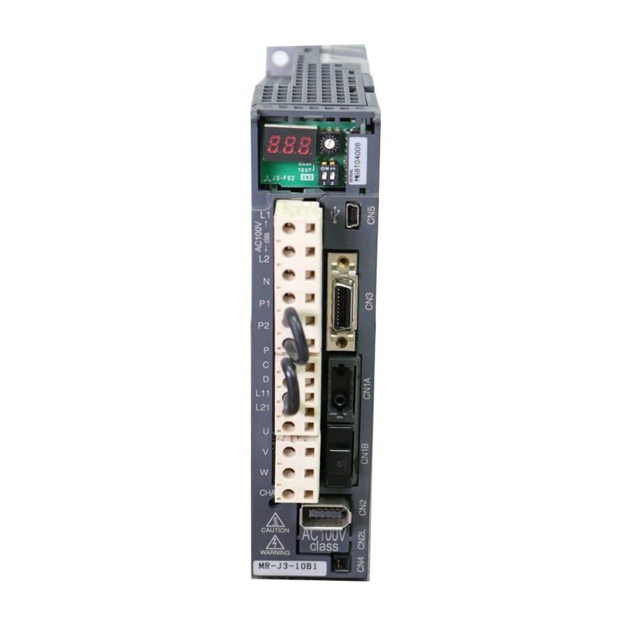
3. SIGNALS AND WIRING 3.4 Connectors and signal arrangements POINT The pin configurations of the connectors are as viewed from the cable connector wiring section. (1) Signal arrangement The servo amplifier front view shown is that of the MR-J3-20B or less. Refer to chapter 9 Outline Drawings for the appearances and connector layouts of the other servo amplifiers. -
Page 79: Signal (Device) Explanations
3. SIGNALS AND WIRING 3.5 Signal (device) explanations For the I/O interfaces (symbols in I/O division column in the table), refer to section 3.7.2. In the control mode field of the table The pin No.s in the connector pin No. column are those in the initial status. (1) Connector applications Connector Name... - Page 80 3. SIGNALS AND WIRING (b) Output device Connector Device Symbol Function/Application Pin No. division Trouble CN3-15 ALM turns off when power is switched off or the protective circuit is DO-1 activated to shut off the base circuit. Without alarm occurring, ALM turns on within about 1s after power-on. Electromagnetic CN3-13 When using this signal, set operation delay time of the electromagnetic...
- Page 81 3. SIGNALS AND WIRING Connector Device Symbol Function/Application Pin No. division Warning When using this signal, make it usable by the setting of parameter DO-1 No.PD07 to PD09. When warning has occurred, WNG turns on. When there is no warning, WNG turns off within about 1.5s after power-on.
-
Page 82: Alarm Occurrence Timing Chart
3. SIGNALS AND WIRING 3.6 Alarm occurrence timing chart When an alarm has occurred, remove its cause, make sure that the operation signal is not being input, ensure safety, and reset the alarm before restarting CAUTION operation. As soon as an alarm occurs, make the Servo off status and interrupt the main circuit power. -
Page 83: Interfaces
3. SIGNALS AND WIRING 3.7 Interfaces 3.7.1 Internal connection diagram Servo amplifier Approx Forced stop 5.6k DICOM (Note 3) (Note 2) (Note 1) Approx (Note 3) 5.6k 24VDC DICOM DOCOM <Isolated> Differential line driver output (35mA or less) Analog monitor 10VDC VBUS 10VDC... -
Page 84: Detailed Description Of Interfaces
3. SIGNALS AND WIRING 3.7.2 Detailed description of interfaces This section provides the details of the I/O signal interfaces (refer to the I/O division in the table) given in section 3.5. Refer to this section and make connection with the external equipment. (1) Digital input interface DI-1 Give a signal with a relay or open collector transistor. - Page 85 3. SIGNALS AND WIRING (3) Encoder pulse output DO-2 (Differential line driver system) (a) Interface Max. output current: 35mA Servo amplifier Servo amplifier Am26LS32 or equivalent High-speed photocoupler (LB, LZ) (LB, LZ) (LBR, LZR) (LBR, LZR) b) Output pulse Servo motor CCW rotation Time cycle (T) is determined by the settings of parameter No.PA15 and PC03.
-
Page 86: Source I/O Interfaces
3. SIGNALS AND WIRING 3.7.3 Source I/O interfaces In this servo amplifier, source type I/O interfaces can be used. In this case, all DI-1 input signals and DO-1 output signals are of source type. Perform wiring according to the following interfaces. (1) Digital input interface DI-1 Servo amplifier EM1,... -
Page 87: Treatment Of Cable Shield External Conductor
3. SIGNALS AND WIRING 3.8 Treatment of cable shield external conductor In the case of the CN2 and CN3 connectors, securely connect the shielded external conductor of the cable to the ground plate as shown in this section and fix it to the connector shell. External conductor Sheath Core... -
Page 88: Sscnet Cable Connection
3. SIGNALS AND WIRING 3.9 SSCNET cable connection POINT Do not see directly the light generated from CN1A CN1B connector of servo amplifier or the end of SSCNET cable. When the light gets into eye, may feel something is wrong for eye. (The light source of SSCNET complies with class1 defined in JIS C6802 or IEC60825-1.) (1) SSCNET cable connection... - Page 89 3. SIGNALS AND WIRING 3) With holding a tab of SSCNET cable connector, make sure to insert it into CN1A CN1B connector of servo amplifier until you hear the click. If the end face of optical code tip is dirty, optical transmission is interrupted and it may cause malfunctions.
-
Page 90: Connection Of Servo Amplifier And Servo Motor
3. SIGNALS AND WIRING 3.10 Connection of servo amplifier and servo motor During power-on, do not open or close the motor power line. Otherwise, a CAUTION malfunction or faulty may occur. 3.10.1 Connection instructions Insulate the connections of the power supply terminals to prevent an electric WARNING shock. -
Page 91: Power Supply Cable Wiring Diagrams
3. SIGNALS AND WIRING 3.10.2 Power supply cable wiring diagrams (1) HF-MP service HF-KP series HF-KP series servo motor (a) When cable length is 10m or less 10m or less MR-PWS1CBL M-A1-L MR-PWS1CBL M-A2-L MR-PWS1CBL M-A1-H Servo amplifier Servo motor MR-PWS1CBL M-A2-H CNP3 AWG 19(red) - Page 92 3. SIGNALS AND WIRING (2) HF-SP series HC-RP series HC-UP series HC-LP series servo motor POINT Insert a contact in the direction shown in the figure. If inserted in the wrong direction, the contact is damaged and falls off. Soldered part or Soldered part Pin No.1 Pin No.1...
- Page 93 3. SIGNALS AND WIRING 2) When the power supply connector and the electromagnetic brake connector are shared. 50m or less Servo amplifier Servo motor DC24V DOCOM DICOM Electromagnetic Forced brake interlock Trouble stop (MBR) (ALM) (EM1) 24VDC power supply for (Note) electromagnetic brake...
- Page 94 3. SIGNALS AND WIRING Power supply connector signal allotment Encoder connector signal allotment MS3102A18-10P Power supply connector signal allotment CM10-R10P MS3102A22-22P CE05-2A22-23PD-B CE05-2A32-17PD-B Terminal Terminal Terminal Signal Signal Signal (earth) (earth) View a View b View b (Note) (Note) Note. For the motor with electromagnetic brake, supply...
- Page 95 3. SIGNALS AND WIRING (3) HA-LP series servo motor (a) Wiring diagrams Refer to section 11.11 for the cables used for wiring. 1) 200V class 50m or less Servo amplifier Servo motor 24VDC Cooling fan (Note 2) DOCOM DICOM Electromagnetic Forced brake interlock Trouble...
- Page 96 3. SIGNALS AND WIRING 2) 400V class (Note4) Cooling fan power supply 50m or less Servo amplifier Servo motor 24VDC Cooling fan (Note 2) DOCOM DICOM Electromagnetic Forced brake interlock Trouble stop (MBR) (ALM) (EM1) 24VDC power supply for (Note 1) electromagnetic brake OHS1...
- Page 97 3. SIGNALS AND WIRING (b) Servo motor terminals Encoder connector CM10-R10P Brake connector Terminal box MS3102A10SL-4P Encoder connector signal Terminal Brake connector signal Terminal Signal Signal allotment allotment CM10-R10P MS3102A10SL-4P (Note) (Note) Note. For the motor with electromagnetic brake, supply electromagnetic brake power (24VDC).
- Page 98 3. SIGNALS AND WIRING Terminal box inside (HA-LP801(4), 12K1(4), 11K1M(4), 15K1M(4), 15K2(4), 22K2(4)) Thermal sensor Cooling fan terminal block terminal block (OHS1,OHS2) M4 screw (BU,BV,BW) M4 screw Terminal block signal Motor power supply terminal block arrangement (U,V,W) M8 screw Encoder connector CM10-R10P OHS1OHS2 Earth terminal M6 screw...
- Page 99 3. SIGNALS AND WIRING Terminal box inside (HA-LP25K1) Encoder connector CM10-R10P Thermal sensor terminal block (OHS1, OHS2) M4 screw Motor power supply terminal block (U, V, W) M10 screw Cooling fan terminal block (BU, BV, BW) M4 screw Earth terminal M6 screw Terminal block signal arrangement BW OHS1 OHS2...
- Page 100 3. SIGNALS AND WIRING Signal Name Abbreviation Description Connect to the motor output terminals (U, V, W) of the servo amplifier. During power-on, do Power supply U V W not open or close the motor power line. Otherwise, a malfunction or faulty may occur. Supply power which satisfies the following specifications.
-
Page 101: Servo Motor With Electromagnetic Brake
3. SIGNALS AND WIRING 3.11 Servo motor with electromagnetic brake 3.11.1 Safety precautions Configure the electromagnetic brake circuit so that it is activated not only by the interface unit signals but also by a forced stop (EM1). Contacts must be open when Circuit must be servo-off, when an alarm occurrence opened during... -
Page 102: Timing Charts
3. SIGNALS AND WIRING 3.11.2 Timing charts (1) Servo-on command (from controller) ON/OFF Tb [ms] after the servo-on is switched off, the servo lock is released and the servo motor coasts. If the electromagnetic brake is made valid in the servo lock status, the brake life may be shorter. Therefore, when using the electromagnetic brake in a vertical lift application or the like, set delay time (Tb) to about the same as the electromagnetic brake operation delay time to prevent a drop. - Page 103 3. SIGNALS AND WIRING (3) Alarm occurrence Dynamic brake Dynamic brake Electromagnetic brake Servo motor speed Electromagnetic brake (10ms) Base circuit Invalid(ON) Electromagnetic brake Electromagnetic operation delay time brake interlock (MBR) Valid(OFF) Alarm (4) Both main and control circuit power supplies off Dynamic brake Dynamic brake (10ms)
-
Page 104: Wiring Diagrams (Hf-Mp Series Hf-Kp Series Servo Motor)
3. SIGNALS AND WIRING 3.11.3 Wiring diagrams (HF-MP series HF-KP series servo motor) POINT For HF-SP series HC-RP series HC-UP series HC-LP series servo motors, refer to section 3.10.2 (2). (1) When cable length is 10m or less 10m or less 24VDC power MR-BKS1CBL M-A1-L supply for... -
Page 105: Grounding
3. SIGNALS AND WIRING 3.12 Grounding Ground the servo amplifier and servo motor securely. To prevent an electric shock, always connect the protective earth (PE) terminal WARNING (terminal marked ) of the servo amplifier with the protective earth (PE) of the control box. -
Page 106: Control Axis Selection
3. SIGNALS AND WIRING 3.13 Control axis selection POINT The control axis number set to rotary axis setting switch (SW1) should be the same as the one set to the servo system controller. Use the rotary axis setting switch (SW1) to set the control axis number for the servo. If the same numbers are set to different control axes in a single communication system, the system will not operate properly. - Page 107 3. SIGNALS AND WIRING MEMO 3 - 52...
-
Page 108: Switching Power On For The First Time
4. STARTUP 4. STARTUP WARNING Do not operate the switches with wet hands. You may get an electric shock. Before starting operation, check the parameters. Some machines may perform unexpected operation. Take safety measures, e.g. provide covers, to prevent accidental contact of hands and parts (cables, etc.) with the servo amplifier heat sink, regenerative resistor, servo motor, etc. -
Page 109: Wiring Check
4. STARTUP 4.1.2 Wiring check (1) Power supply system wiring Before switching on the main circuit and control circuit power supplies, check the following items. (a) Power supply system wiring The power supplied to the power input terminals (L ) of the servo amplifier should satisfy the defined specifications. -
Page 110: Surrounding Environment
4. STARTUP 2) When regenerative option is used over 5kW for 200V class and 3.5kW for 400V class The lead of built-in regenerative resistor connected to P terminal and D terminal of TE1 terminal block should not be connected. The generative brake option should be connected to P terminal and C terminal. A twisted cable should be used when wiring is over 5m and under 10m. -
Page 111: Start Up
4. STARTUP 4.2 Start up Connect the servo motor with a machine after confirming that the servo motor operates properly alone. (1) Power on When the main and control circuit power supplies are switched on, "b01" (for the first axis) appears on the servo amplifier display. -
Page 112: Servo Amplifier Display
4. STARTUP 4.3 Servo amplifier display On the servo amplifier display (three-digit, seven-segment display), check the status of communication with the servo system controller at power-on, check the axis number, and diagnose a fault at occurrence of an alarm. (1) Display sequence Servo amplifier power ON Waiting for servo system controller power to switch ON... - Page 113 4. STARTUP (2) Indication list Indication Status Description Power of the servo amplifier was switched on at the condition that the power of servo system controller is OFF. The axis No. set to the servo system controller does not match the axis No. set with the rotary axis setting switch (SW1) of the servo amplifier.
-
Page 114: Test Operation
4. STARTUP 4.4 Test operation Before starting actual operation, perform test operation to make sure that the machine operates normally. Refer to section 4.2 for the power on and off methods of the servo amplifier. POINT If necessary, verify controller program by using motorless operation. Refer to section 4.5.2 for the motorless operation. -
Page 115: Test Operation Mode
4. STARTUP 4.5 Test operation mode The test operation mode is designed for servo operation confirmation and not for machine operation confirmation. Do not use this mode with the machine. Always CAUTION use the servo motor alone. If an operation fault occurred, use the forced stop (EM1) to make a stop. POINT The content described in this section indicates the environment that servo amplifier and personal computer are directly connected. - Page 116 4. STARTUP (c) Program operation Positioning operation can be performed in two or more operation patterns combined, without using the servo system controller. Use this operation with the forced stop reset. This operation may be used independently of whether the servo is on or off and whether the servo system controller is connected or not.
-
Page 117: Motorless Operation In Controller
4. STARTUP 4.5.2 Motorless operation in controller POINT Use motor-less operation which is available by making the servo system controller parameter setting. Motorless operation is done while connected with the servo system controller. (1) Motorless operation Without connecting the servo motor, output signals or status displays can be provided in response to the servo system controller commands as if the servo motor is actually running. -
Page 118: Basic Setting Parameters (No.pa )
5. PARAMETERS 5. PARAMETERS Never adjust or change the parameter values extremely as it will make operation CAUTION instable. In this servo amplifier, the parameters are classified into the following groups on a function basis. Parameter Group Main Description Basic setting parameters Make basic setting with these parameters. -
Page 119: Parameter Write Inhibit
5. PARAMETERS 5.1.2 Parameter write inhibit Parameter Initial Value Unit Setting Range Symbol Name PA19 *BLK Parameter write inhibit 000Bh Refer to the text. POINT This parameter is made valid when power is switched off, then on after setting, or when the controller reset has been performed. In the factory setting, this servo amplifier allows changes to the basic setting parameter, gain/filter parameter and extension setting parameter settings. -
Page 120: Selection Of Regenerative Option
5. PARAMETERS 5.1.3 Selection of regenerative option Parameter Initial Value Unit Setting Range Symbol Name PA02 **REG Regenerative option 0000h Refer to the text. POINT This parameter value and switch power off once, then switch it on again to make that parameter setting valid. Wrong setting may cause the regenerative option to burn. -
Page 121: Using Absolute Position Detection System
5. PARAMETERS 5.1.4 Using absolute position detection system Parameter Initial Value Unit Setting Range Symbol Name PA03 *ABS Absolute position detection system 0000h Refer to the text. POINT This parameter is made valid when power is switched off, then on after setting, or when the controller reset has been performed. -
Page 122: Auto Tuning
5. PARAMETERS 5.1.6 Auto tuning Parameter Initial Value Unit Setting Range Symbol Name PA08 Auto tuning mode 0001h Refer to the text. PA09 Auto tuning response 1 to 32 Make gain adjustment using auto tuning. Refer to section 6.2 for details. (1) Auto tuning mode (parameter No. -
Page 123: In-Position Range
5. PARAMETERS (2) Auto tuning response (parameter No. PA09) If the machine hunts or generates large gear sound, decrease the set value. To improve performance, e.g. shorten the settling time, increase the set value. Guideline for Machine Guideline for Machine Setting Response Setting... -
Page 124: Selection Of Servo Motor Rotation Direction
5. PARAMETERS 5.1.8 Selection of servo motor rotation direction Parameter Initial Value Unit Setting Range Symbol Name PA14 *POL Rotation direction selection POINT This parameter is made valid when power is switched off, then on after setting, or when the controller reset has been performed. Select servo motor rotation direction relative. - Page 125 5. PARAMETERS (1) For output pulse designation Set " " (initial value) in parameter No. PC03. Set the number of pulses per servo motor revolution. Output pulse set value [pulses/rev] For instance, set "5600" to Parameter No. PA15, the actually output A/B-phase pulses are as indicated below: 5600 A B-phase output pulses...
-
Page 126: Gain/Filter Parameters (No. Pb )
5. PARAMETERS 5.2 Gain/filter parameters (No. PB POINT Parameter whose symbol is preceded by * is made valid with the following conditions. * : Set the parameter value, switch power off once after setting, and then switch it on again, or perform the controller reset. 5.2.1 Parameter list Symbol Name... -
Page 127: Detail List
5. PARAMETERS Symbol Name Initial Value Unit PB42 For manufacturer setting 1125 PB43 0004h PB44 PB45 0000h 5.2.2 Detail list Initial Setting Symbol Name and Function Unit Value Range PB01 FILT Adaptive tuning mode (adaptive filter ) 0000h Select the setting method for filter tuning. Setting this parameter to " 1"... - Page 128 5. PARAMETERS Initial Setting Symbol Name and Function Unit Value Range PB02 VRFT Vibration suppression control tuning mode (advanced vibration suppression control) 0000h This parameter cannot be used in the speed control mode. The vibration suppression is valid when the parameter No. PA08 (auto tuning) setting is "...
- Page 129 5. PARAMETERS Initial Setting Symbol Name and Function Unit Value Range PB06 Ratio of load inertia moment to servo motor inertia moment times Used to set the ratio of the load inertia moment to the servo motor shaft inertia moment. When auto tuning mode 1 and interpolation mode is selected, the result of auto tuning is 300.0 automatically used.
- Page 130 5. PARAMETERS Initial Setting Symbol Name and Function Unit Value Range PB14 NHQ1 Notch shape selection 1 0000h Refer to Used to selection the machine resonance suppression filter 1. Name function column. Notch depth selection Setting value Depth Gain Deep 40dB 14dB Shallow...
- Page 131 5. PARAMETERS Initial Setting Symbol Name and Function Unit Value Range PB18 Low-pass filter setting 3141 rad/s Set the low-pass filter. Setting parameter No. PB23 (low-pass filter selection) to " " automatically 18000 changes this parameter. When parameter No. PB23 is set to " ", this parameter can be set manually.
- Page 132 5. PARAMETERS Initial Setting Symbol Name and Function Unit Value Range PB26 *CDP Gain changing selection 0000h Refer to Select the gain changing condition. (Refer to section 7.6.) Name function column. Gain changing selection Under any of the following conditions, the gains change on the basis of the parameter No.
- Page 133 5. PARAMETERS Initial Setting Symbol Name and Function Unit Value Range PB34 VRF2B Gain changing vibration suppression control resonance frequency setting 100.0 This parameter cannot be used in the speed control mode. Set the resonance frequency for vibration suppression control when the gain changing is 100.0 valid.
-
Page 134: Extension Setting Parameters (No. Pc )
5. PARAMETERS 5.3 Extension setting parameters (No. PC POINT Parameter whose symbol is preceded by * is made valid with the following conditions. * : Set the parameter value, switch power off once after setting, and then switch it on again, or perform the controller reset. **: Set the parameter value, switch power off once, and then switch it on again. -
Page 135: List Of Details
5. PARAMETERS 5.3.2 List of details Initial Setting Symbol Name and Function Unit Value Range PC01 Error excessive alarm level (Note 2) This parameter cannot be used in the speed control mode. (Note 1) Set error excessive alarm level with rotation amount of servo motor. Note 1. - Page 136 5. PARAMETERS Initial Setting Symbol Name and Function Unit Value Range PC06 *COP3 Function selection C-3 0000h Refer to Name Select the error excessive alarm level setting for parameter No.PC01. function column. Error excessive alarm level setting selection 0: 1 [rev]unit 1: 0.1 [rev]unit...
- Page 137 5. PARAMETERS Initial Setting Symbol Name and Function Unit Value Range PC12 Analog monitor 2 offset -999 Used to set the offset voltage of the analog monitor2 (MO2) output. PC13 MOSDL Analog monitor feedback position output standard data Low pulse -9999 Used to set the standard position of feedback output with analog monitor 1 (M01) or 2 (M02).
-
Page 138: Analog Monitor
5. PARAMETERS 5.3.3 Analog monitor The servo status can be output to two channels in terms of voltage. The servo status can be monitored using an ammeter. (1) Setting Change the following digits of parameter No. PC09, PC10: Parameter No. PC09 0 0 0 Analog monitor (MO1) output selection (Signal output to across MO1-LG) - Page 139 5. PARAMETERS Setting Output item Description Setting Output item Description Droop pulses (Note 1) CCW direction Droop pulses (Note 1) CCW direction 10[V] 10[V] ( 10V/100 pulses) ( 10V/1000 pulses) 100[pulse] 1000[pulse] 100[pulse] 1000[pulse] -10[V] -10[V] CW direction CW direction Droop pulses CCW direction Droop pulses...
-
Page 140: Alarm History Clear
5. PARAMETERS (3) Analog monitor block diagram Speed Current Droop pulse command command Bus voltage Speed Position Differ- command Current encoder command ential Position Current Speed Servo Motor received control control control from a controller Encoder Current feedback Differ- ential Position feedback Position feedback data returned to... -
Page 141: I/O Setting Parameters (No. Pd )
5. PARAMETERS 5.4 I/O setting parameters (No. PD POINT Parameter whose symbol is preceded by * is made valid with the following conditions. * : Set the parameter value, switch power off once after setting, and then switch it on again, or perform the controller reset. 5.4.1 Parameter list Symbol Name... -
Page 142: List Of Details
5. PARAMETERS 5.4.2 List of details Initial Setting Symbol Name and Function Unit Value Range PD01 For manufacturer setting 0000h Do not change this value by any means. PD02 0000h PD03 0000h PD04 0000h PD05 0000h PD06 0000h PD07 *DO1 Output signal device selection 1 (CN3-13) 0005h Refer to... - Page 143 5. PARAMETERS Initial Setting Symbol Name and Function Unit Value Range PD10 For manufacturer setting 0000h Do not change this value by any means. PD11 0004h PD12 0000h PD13 0000h PD14 *DOP3 Function selection D-3 0000h Refer to Set the ALM output signal at warning occurrence. Name function column.
-
Page 144: Different Adjustment Methods
6. GENERAL GAIN ADJUSTMENT 6. GENERAL GAIN ADJUSTMENT 6.1 Different adjustment methods 6.1.1 Adjustment on a single servo amplifier The gain adjustment in this section can be made on a single servo amplifier. For gain adjustment, first execute auto tuning mode 1. If you are not satisfied with the results, execute auto tuning mode 2 and manual mode in this order. -
Page 145: Adjustment Using Mr Configurator
6. GENERAL GAIN ADJUSTMENT (2) Adjustment sequence and mode usage START Usage Used when you want to Interpolation made for 2 or more match the position gain (PG1) axes? between 2 or more axes. Interpolation mode Normally not used for other purposes. -
Page 146: Auto Tuning Mode
6. GENERAL GAIN ADJUSTMENT 6.2 Auto tuning 6.2.1 Auto tuning mode The servo amplifier has a real-time auto tuning function which estimates the machine characteristic (load inertia moment ratio) in real time and automatically sets the optimum gains according to that value. This function permits ease of gain adjustment of the servo amplifier. -
Page 147: Auto Tuning Mode Operation
6. GENERAL GAIN ADJUSTMENT 6.2.2 Auto tuning mode operation The block diagram of real-time auto tuning is shown below. Load inertia Automatic setting moment Encoder Loop gains Command Current Servo PG1,VG1 control motor PG2,VG2,VIC Current feedback Real-time auto Position/speed Set 0 or 1 to turn on. tuning section feedback Load inertia... -
Page 148: Adjustment Procedure By Auto Tuning
6. GENERAL GAIN ADJUSTMENT 6.2.3 Adjustment procedure by auto tuning Since auto tuning is made valid before shipment from the factory, simply running the servo motor automatically sets the optimum gains that match the machine. Merely changing the response level setting value as required completes the adjustment. -
Page 149: Response Level Setting In Auto Tuning Mode
6. GENERAL GAIN ADJUSTMENT 6.2.4 Response level setting in auto tuning mode Set the response (The first digit of parameter No. PA09) of the whole servo system. As the response level setting is increased, the track ability and settling time for a command decreases, but a too high response level will generate vibration. -
Page 150: Manual Mode 1 (Simple Manual Adjustment)
6. GENERAL GAIN ADJUSTMENT 6.3 Manual mode 1 (simple manual adjustment) If you are not satisfied with the adjustment of auto tuning, you can make simple manual adjustment with three parameters. POINT If machine resonance occurs, filter tuning mode (parameter No. PB01) or machine resonance suppression filter (parameter No. - Page 151 6. GENERAL GAIN ADJUSTMENT (c)Adjustment description 1) Speed loop gain (parameter No. PB09) This parameter determines the response level of the speed control loop. Increasing this value enhances response but a too high value will make the mechanical system liable to vibrate. The actual response frequency of the speed loop is as indicated in the following expression: Speed loop gain setting Speed loop response...
- Page 152 6. GENERAL GAIN ADJUSTMENT (2) For position control (a) Parameters The following parameters are used for gain adjustment: Parameter No. Abbreviation Name PB06 Ratio of load inertia moment to servo motor inertia moment PB07 Model loop gain PB08 Position loop gain PB09 Speed loop gain PB10...
- Page 153 6. GENERAL GAIN ADJUSTMENT (c) Adjustment description 1) Speed loop gain (VG2: parameter No. PB09) This parameter determines the response level of the speed control loop. Increasing this value enhances response but a too high value will make the mechanical system liable to vibrate. The actual response frequency of the speed loop is as indicated in the following expression: Speed loop gain 2 setting Speed loop response...
-
Page 154: Interpolation Mode
6. GENERAL GAIN ADJUSTMENT 6.4 Interpolation mode The interpolation mode is used to match the position loop gains of the axes when performing the interpolation operation of servo motors of two or more axes for an X-Y table or the like. In this mode, the model loop gain and speed loop gain which determine command track ability are set manually and the other parameter for gain adjustment are set automatically. -
Page 155: Differences Between Melservo-J2-Super And Melservo-J3 In Auto Tuning
6. GENERAL GAIN ADJUSTMENT 6.5 Differences between MELSERVO-J2-Super and MELSERVO-J3 in auto tuning To meet higher response demands, the MELSERVO-J3 series has been changed in response level setting range from the MELSERVO-J2S-Super series. The following table lists comparison of the response level setting. -
Page 156: Adaptive Filter
7. SPECIAL ADJUSTMENT FUNCTIONS 7. SPECIAL ADJUSTMENT FUNCTIONS POINT The functions given in this chapter need not be used generally. Use them if you are not satisfied with the machine status after making adjustment in the methods in chapter 7. If a mechanical system has a natural resonance point, increasing the servo system response level may cause the mechanical system to produce resonance (vibration or unusual noise) at that resonance frequency. - Page 157 7. SPECIAL ADJUSTMENT FUNCTIONS (2) Parameters The operation of adaptive tuning mode (parameter No. PB01). Parameter No.60 0 0 0 Filter tuning mode selection Setting Filter adjustment mode Automatically set parameter Filter OFF (Note) Parameter No. PB13 Filter tuning mode Parameter No.
- Page 158 7. SPECIAL ADJUSTMENT FUNCTIONS (3) Adaptive tuning mode procedure Adaptive tuning adjustment Operation Is the target response reached? Increase the response setting. Has vibration or unusual noise occurred? Execute or re-execute adaptive tuning. (Set parameter No. PB01 to "0001".) Tuning ends automatically after the If assumption fails after tuning is executed at predetermined period of time.
-
Page 159: Machine Resonance Suppression Filter
7. SPECIAL ADJUSTMENT FUNCTIONS POINT "Filter OFF" enables a return to the factory-set initial value. When adaptive tuning is executed, vibration sound increases as an excitation signal is forcibly applied for several seconds. When adaptive tuning is executed, machine resonance is detected for a maximum of 10 seconds and a filter is generated. - Page 160 7. SPECIAL ADJUSTMENT FUNCTIONS (2) Parameters (a) Machine resonance suppression filter 1 (parameter No. PB13, PB14) Set the notch frequency, notch depth and notch width of the machine resonance suppression filter 1 (parameter No. PB13, PB14) When you have made adaptive filter tuning mode (parameter No. PB01) "manual mode", set up the machine resonance suppression filter 1 becomes effective.
-
Page 161: Advanced Vibration Suppression Control
7. SPECIAL ADJUSTMENT FUNCTIONS 7.4 Advanced vibration suppression control (1) Operation Vibration suppression control is used to further suppress machine end vibration, such as workpiece end vibration and base shake. The motor side operation is adjusted for positioning so that the machine does not shake. - Page 162 7. SPECIAL ADJUSTMENT FUNCTIONS (3) Vibration suppression control tuning mode procedure Vibration suppression control tuning adjustment Operation Is the target response reached? Increase the response setting. Has vibration of workpiece end/device increased? Stop operation. Execute or re-execute vibration suppression control tuning. (Set parameter No.
- Page 163 7. SPECIAL ADJUSTMENT FUNCTIONS (4) Vibration suppression control manual mode Measure work end vibration and device shake with the machine analyzer or external measuring instrument, and set the vibration suppression control vibration frequency (parameter No. PB19) and vibration suppression control resonance frequency (parameter No. PB20) to set vibration suppression control manually.
- Page 164 7. SPECIAL ADJUSTMENT FUNCTIONS POINT When machine end vibration does not show up in motor end vibration, the setting of the motor end vibration frequency does not produce an effect. When the anti-resonance frequency and resonance frequency can be confirmed using the machine analyzer or external FFT device, do not set the same value but set different values to improve the vibration suppression performance.
-
Page 165: Low-Pass Filter
7. SPECIAL ADJUSTMENT FUNCTIONS 7.5 Low-pass filter (1) Function When a ballscrew or the like is used, resonance of high frequency may occur as the response level of the servo system is increased. To prevent this, the low-pass filter is factory-set to be valid for a torque command. -
Page 166: Function Block Diagram
7. SPECIAL ADJUSTMENT FUNCTIONS 7.6.2 Function block diagram The valid loop gains PG2, VG2, VIC and GD2 of the actual loop are changed according to the conditions selected by gain changing selection CDP (parameter No. PB26) and gain changing condition CDS (parameter No. -
Page 167: Parameters
7. SPECIAL ADJUSTMENT FUNCTIONS 7.6.3 Parameters When using the gain changing function, always set " 3" in parameter No. PA08 (auto tuning) to choose the manual mode of the gain adjustment modes. The gain changing function cannot be used in the auto tuning mode. - Page 168 7. SPECIAL ADJUSTMENT FUNCTIONS (1) Parameters No. PB06 to PB10 These parameters are the same as in ordinary manual adjustment. Gain changing allows the values of ratio of load inertia moment to servo motor inertia moment, position loop gain, speed loop gain and speed integral compensation to be changed.
-
Page 169: Gain Changing Operation
7. SPECIAL ADJUSTMENT FUNCTIONS 7.6.4 Gain changing operation This operation will be described by way of setting examples. (1) When you choose changing by external input (a) Setting Parameter No. Abbreviation Name Setting Unit PB07 Model loop gain rad/s Ratio of load inertia moment to servo motor PB06 times inertia moment... - Page 170 7. SPECIAL ADJUSTMENT FUNCTIONS (2) When you choose changing by droop pulses (a) Setting Parameter No. Abbreviation Name Setting Unit PB07 Model loop gain rad/s Ratio of load inertia moment to servo motor PB06 times inertia moment PB08 Position loop gain rad/s PB09 Speed loop gain...
- Page 171 7. SPECIAL ADJUSTMENT FUNCTIONS MEMO 7 - 16...
-
Page 172: Troubleshooting
8. TROUBLESHOOTING 8. TROUBLESHOOTING POINT As soon as an alarm occurs, make the Servo off status and interrupt the main circuit power. If an alarm/warning has occurred, refer to this chapter and remove its cause. 8.1 Alarms and warning list When a fault occurs during operation, the corresponding alarm or warning is displayed. -
Page 173: Remedies For Alarms
8. TROUBLESHOOTING 8.2 Remedies for alarms When any alarm has occurred, eliminate its cause, ensure safety, then reset the alarm, and restart operation. Otherwise, injury may occur. If an absolute position erase (25) occurred, always make home position setting CAUTION again. -
Page 174: Troubleshooting
8. TROUBLESHOOTING Display Name Definition Cause Action Memory error 1 RAM, memory fault Faulty parts in the servo amplifier Change the servo amplifier. (RAM) Checking method Clock error Printed board fault Alarm (any of 12 and 13) occurs if power is switched on after disconnection of all cables but the control circuit power supply cables. - Page 175 8. TROUBLESHOOTING Display Name Definition Cause Action Regenerative Permissible 1. Wrong setting of parameter No. Set correctly. error regenerative power PA02 of the built-in 2. Built-in regenerative resistor or Connect correctly regenerative resistor regenerative option is not or regenerative connected. option is exceeded.
- Page 176 8. TROUBLESHOOTING Display Name Definition Cause Action Overvoltage The following shows 1. Regenerative option is not used. Use the regenerative option. the input value of 2. Though the regenerative option is Set correctly. used, the parameter No.PA02 converter bus setting is " 00 (not used)".
- Page 177 8. TROUBLESHOOTING Display Name Definition Cause Action Parameter error Parameter setting is 1. Servo amplifier fault caused the Change the servo amplifier. wrong. parameter setting to be rewritten. 2. There is a parameter whose value Change the parameter value to within the was set to outside the setting range setting range.
- Page 178 8. TROUBLESHOOTING Display Name Definition Cause Action Overload 2 Machine collision or 1. Machine struck something. 1. Review operation pattern. the like caused max. 2. Install limit switches. For the time of the 2. Wrong connection of servo motor. Connect correctly. alarm occurrence, Servo amplifier's output terminals U, refer to the section...
-
Page 179: Remedies For Warnings
8. TROUBLESHOOTING Display Name Definition Cause Action (Note) Watchdog CPU, parts faulty Fault of parts in servo amplifier Change servo amplifier. Checking method Alarm (888) occurs if power is switched on after disconnection of all cables but the control circuit power supply cable. - Page 180 8. TROUBLESHOOTING Display Name Definition Cause Action Absolute position Absolute position encoder 1. Noise entered the encoder. Take noise suppression counter warning pulses faulty. measures. 2. Encoder faulty. Change servo motor. The multi-revolution 3. The movement amount from the home Make home position setting counter value of the position exceeded a 32767 rotation or...
- Page 181 8. TROUBLESHOOTING MEMO 8 - 10...
-
Page 182: Outline Drawings
9. OUTLINE DRAWINGS 9. OUTLINE DRAWINGS 9.1 Servo amplifier (1) MR-J3-10B MR-J3-20B MR-J3-10B1 MR-J3-20B1 [Unit: mm] 6 mounting hole Approx.80 (Note) CNP1 (Note) CNP2 CNP3 Approx. Approx.68 25.5 With MR-J3BAT Note. This data applies to the 3-phase or 1-phase 200 to 230VAC power supply models. For a single-phase, 100 to 120VAC power supply, refer to the terminal signal layout. - Page 183 9. OUTLINE DRAWINGS (2) MR-J3-40B MR-J3-60B MR-J3-40B1 [Unit: mm] 6 mounting hole Approx.80 (Note) CNP1 (Note) CNP2 CNP3 CHARGE Approx. Approx.68 25.5 With MR-J3BAT Note. This data applies to the 3-phase or 1-phase 200 to 230VAC power supply models. For a single-phase, 100 to 120VAC power supply, refer to the terminal signal layout. Mass: 1.0 [kg] (2.21 [lb]) Terminal signal layout Mounting screw...
- Page 184 9. OUTLINE DRAWINGS (3) MR-J3-70B MR-J3-100B [Unit: mm] 6 mounting hole Approx.80 CNP1 CNP2 CNP3 Cooling fan wind direction Approx.68 Approx.25.5 With MR-J3BAT Mass: 1.4 [kg] (3.09 [lb]) Terminal signal layout Mounting screw Screw size: M5 Tightening torque: 3.24 [N m] (28.7 [lb in]) PE terminal Approx.
- Page 185 9. OUTLINE DRAWINGS (4) MR-J3-60B4 MR-J3-100B4 [Unit: mm] Approx. 80 6mounting hole CNP1 CNP2 CNP3 12 42 Approx. 68 Approx. 25.5 With MR-J3BAT Mass: 1.7 [kg] (3.75 [lb]) Mounting screw Terminal signal layout Screw size: M5 Tightening torque: 3.24 [N m] (28.7 [lb in]) PE terminal Approx.
- Page 186 9. OUTLINE DRAWINGS (5) MR-J3-200B MR-J3-350B [Unit: mm] 6 mounting hole Approx.80 21.4 Cooling fan Approx. wind direction 25.5 Approx.68 With MR-J3BAT Mass: 2.3 [kg] (5.07 [lb]) Mounting screw Terminal signal layout Screw size: M5 Tightening torque: 3.24 [N m] (28.7 [lb in]) PE terminal Approx.
- Page 187 9. OUTLINE DRAWINGS (6) MR-J3-200B4 [Unit: mm] 6mounting hole Approx. 80 CNP1 CNP2 CNP3 Approx. Cooling fan 25.5 wind direction Approx. 68 With MR-J3BAT Mass: 2.1 [kg] (4.63 [lb]) Mounting screw Terminal signal layout Screw size: M5 Tightening torque: 3.24 [N m] (28.7 [lb in] PE terminal Approx.
- Page 188 9. OUTLINE DRAWINGS (7) MR-J3-350B4 MR-J3-500B(4) [Unit: mm] Approx. 80 2- 6 mounting hole 131.5 68.5 Cooling fan Terminal layout wind direction (Terminal cover open) Cooling fan With MR-J3BAT CHARGE 20.5 3 places for ground (M4) Built-in regenerative resistor lead terminal fixing screw Mass: 4.6 [kg] (10.1 [lb]) Terminal signal layout...
- Page 189 9. OUTLINE DRAWINGS (8) MR-J3-700B(4) [Unit: mm] Approx.80 2- 6 mounting hole Cooling fan Terminal layout wind direction (Terminal cover open) Cooling fan With MR-J3BAT CHARGE 20.5 3 places for ground (M4) Built-in regenerative resistor lead terminal fixing screw Mass: 6.2 [kg] (13.7[lb]) Terminal signal layout Mounting screw Screw size: M5...
- Page 190 9. OUTLINE DRAWINGS (9) MR-J3-11KB(4) to 22KB(4) [Unit: mm] Approx. 80 Cooling fan 12mounting hole wind direction With MR-J3BAT Rating plate 123.5 6 26 Approx. 260 Approx. 12 Approx. 12 236 0.5 4-M10 screw Servo amplifier Mass[kg]([lb]) MR-J3-11KB(4) 18.0 (40) MR-J3-15KB(4) 18.0 (40) MR-J3-22KB(4)
- Page 191 9. OUTLINE DRAWINGS 9.2 Connector (1) CN1A CN1B connector [Unit: mm] F0-PF2D103 F0-PF2D103-S 17.6 17.6 20.9 20.9 (2) Miniature delta ribbon (MDR) system (3M) (a) One-touch lock type [Unit: mm] Logo etc, are indicated here. 12.7 Each type of dimension Connector Shell kit 10120-3000PE...
- Page 192 9. OUTLINE DRAWINGS (b) Jack screw M2.6 type This is not available as option. [Unit: mm] Logo etc, are indicated here. 12.7 Each type of dimension Connector Shell kit 10120-3000PE 10320-52F0-008 22.0 33.3 14.0 10.0 12.0 27.4 (3) SCR connector system (3M) Receptacle : 36210-0100PL Shell kit : 36310-3200-008...
- Page 193 9. OUTLINE DRAWINGS MEMO 9 - 12...
-
Page 194: Characteristics
10. CHARACTERISTICS 10. CHARACTERISTICS 10.1 Overload protection characteristics An electronic thermal relay is built in the servo amplifier to protect the servo motor and servo amplifier from overloads. Overload 1 alarm (50) occurs if overload operation performed is above the electronic thermal relay protection curve shown in any of Figs 10.1. - Page 195 10. CHARACTERISTICS 10000 1000 During operation During servo lock (Note) Load ratio [%] MR-J3-11KB(4) to MR-J3-22KB(4) Note. If operation that generates torque more than 100% of the rating is performed with an abnormally high frequency in a servo motor stop status (servo lock status) or in a 30r/min or less low-speed operation status, the servo amplifier may fail even when the electronic thermal relay protection is not activated.
-
Page 196: Power Supply Equipment Capacity And Generated Loss
10. CHARACTERISTICS 10.2 Power supply equipment capacity and generated loss (1) Amount of heat generated by the servo amplifier Table 10.1 indicates servo amplifiers' power supply capacities and losses generated under rated load. For thermal design of an enclosure, use the values in Table 10.1 in consideration for the worst operating conditions. - Page 197 10. CHARACTERISTICS (Note 1) (Note 2) Area required for Servo amplifier Servo motor Power supply Servo amplifier-generated heat[W] heat dissipation capacity[kVA] At rated torque With servo off HF-SP702 (4) 10.0 HA-LP702 10.6 MR-J3-700B (4) HA-LP601 (4) 10.0 HA-LP701M (4) 11.0 HC-LP11K2 (4) 16.0 11.0...
- Page 198 10. CHARACTERISTICS (2) Heat dissipation area for enclosed servo amplifier The enclosed control box (hereafter called the control box) which will contain the servo amplifier should be designed to ensure that its temperature rise is within 10 at the ambient temperature of 40 . (With a 5 (41 ) safety margin, the system should operate within a maximum 55 (131 ) limit.) The necessary enclosure heat dissipation area can be calculated by Equation 10.1:...
-
Page 199: Dynamic Brake Characteristics
10. CHARACTERISTICS 10.3 Dynamic brake characteristics 10.3.1 Dynamic brake operation (1) Calculation of coasting distance Fig. 10.3 shows the pattern in which the servo motor comes to a stop when the dynamic brake is operated. Use Equation 10.2 to calculate an approximate coasting distance to a stop. The dynamic brake time constant varies with the servo motor and machine operation speeds. - Page 200 10. CHARACTERISTICS 500 1000 1500 2000 2500 3000 1000 1500 2000 Speed [r/min] Speed [r/min] HF-SP1000r/min series HF-SP2000r/min series 22K1M 20K1 11K1M 12K1 15K1 15K1M 701M 25K1 800 1000 1200 1000 1500 2000 Speed[r/min] Speed[r/min] HA-LP1000r/min series HA-LP1500r/min series 15K2 11K2 22K2 1000...
-
Page 201: The Dynamic Brake At The Load Inertia Moment
If there is a possibility that the load inertia moment may exceed the value, contact Mitsubishi. The values of the load inertia moment ratio in the table are the values at the maximum rotation speed of the servo motor. -
Page 202: Cable Flexing Life
10. CHARACTERISTICS Servo motor Servo HA-LP amplifier HF-SP 4 HA-LP 14 HA-LP 24 MR-J3-60B4 5 (Note 1) MR-J3-100B4 5 (Note 1) MR-J3-200B4 MR-J3-350B4 5 (Note 1) MR-J3-500B4 5 (Note 1) MR-J3-700B4 5 (Note 1) MR-J3-11KB4 (Note 2) MR-J3-15KB4 (Note 2) MR-J3-22KB4 (Note 2) Note 1. -
Page 203: Inrush Currents At Power-On Of Main Circuit And Control Circuit
10. CHARACTERISTICS 10.5 Inrush currents at power-on of main circuit and control circuit The following table indicates the inrush currents (reference data) that will flow when the maximum permissible voltage (200V class: 253VAC, 400V class: 528VAC) is applied at the power supply capacity of 2500kVA and the wiring length of 1m (3.28ft). -
Page 204: Cable/Connector Sets
11. OPTIONS AND AUXILIARY EQUIPMENT 11. OPTIONS AND AUXILIARY EQUIPMENT Before connecting any option or peripheral equipment, turn off the power and wait for 15 minutes or more until the charge lamp turns off. Then, confirm that the WARNING voltage between P( ) and N( ) is safe with a voltage tester and others. Otherwise, an electric shock may occur. -
Page 205: Combinations Of Cable/Connector Sets
11. OPTIONS AND AUXILIARY EQUIPMENT 11.1.1 Combinations of cable/connector sets Servo system Cont Personal computer 32)33)34) Servo amplifier Servo amplifier 1)2) Note CNP1 CN1A CN1A 32)33)34) CNP2 CN1B CN1B CNP3 (Servo amplifier attachment) Direct connection type (cable length 10m or less, IP65) 15)16)17)18) Junction type (cable length more than 10m, IP20) 21)22) - Page 206 11. OPTIONS AND AUXILIARY EQUIPMENT From previous page a) From previous page b) 24)25) Servo motor 30)39)40) HC-RP HC-UP HC-LP Power supply Encoder Brake connector connector connector 24)25) Servo motor HA-LP Terminal box Product Model Description Application 1) Servo Supplied with amplifier servo power supply...
- Page 207 11. OPTIONS AND AUXILIARY EQUIPMENT Product Model Description Application 2) Servo Supplied with amplifier servo power supply amplifiers of connector 2kW and 3.5kW in 200V CNP1 connector: CNP2 connector: CNP3 connector: class PC4/6-STF-7.62- 54927-0510 PC4/3-STF-7.62- CRWH (Molex) CRWH (Phoenix Contact) (Phoenix Contact) <Applicable cable example>...
- Page 208 11. OPTIONS AND AUXILIARY EQUIPMENT Product Model Description Application 9) Motor brake MR-BKS1CBL M-A1-L IP65 Brake connector cable Cable length: 2 5 10m Load side lead 10) Motor brake MR-BKS1CBL M-A1-H IP65 HF-MP series cable Cable length: 2 5 10m Load side lead HF-KP series Long flex life...
- Page 209 11. OPTIONS AND AUXILIARY EQUIPMENT Product Model Description Application 21) Encoder MR-EKCBL IP20 cable Cable length: 20 30m 22) Encoder MR-EKCBL IP20 cable Cable length: Long flex life For HF-MP HF-KP series 20 30 40 50m Refer to section 11.1.2 (2) for details. 23) Encoder MR-ECNM IP20...
- Page 210 11. OPTIONS AND AUXILIARY EQUIPMENT Product Model Description Application 32) SSCNET MR-J3BUS M Connector: PF-2D103 Connector: PF-2D103 Inside panel cable Cable length: 0.15 to 3m (Japan Aviation Electronics (Japan Aviation Electronics standard cord (Refer to section 11.1.5.) Industry, Ltd.) Industry, Ltd.) 33) SSCNET MR-J3BUS M-A Outside panel...
-
Page 211: Encoder Cable/Connector Sets
11. OPTIONS AND AUXILIARY EQUIPMENT 11.1.2 Encoder cable/connector sets (1) MR-J3ENCBL M-A1-L/H MR-J3ENCBL M-A2-L/H These cables are encoder cables for the HF-MP HF-KP series servo motors. The numerals in the Cable Length field of the table are the symbols entered in the part of the cable model. - Page 212 11. OPTIONS AND AUXILIARY EQUIPMENT (b) Cable internal wiring diagram MR-J3ENCBL2M-L/-H MR-J3ENCBL5M-L/-H MR-J3ENCBL10M-L/-H Encoder side Servo amplifier connector side connector Plate (2) MR-EKCBL M-L/H POINT The following encoder cables are of four-wire type. When using any of these encoder cables, set parameter No. PC04 to "1 "...
- Page 213 11. OPTIONS AND AUXILIARY EQUIPMENT (a) Connection of servo amplifier and servo motor Servo amplifier MR-EKCBL M-L MR-J3JCBL03M-L MR-EKCBL M-H Cable length: 0.3m Servo motor HF-MP HF-KP Cable Model 1) For CN2 Connector 2) For Encoder Connector MR-EKCBL Connector set: 54599-1019(Molex) Housing: 1-172161-9 Receptacle: 36210-0100PL Crimping pin: 170359-1...
- Page 214 11. OPTIONS AND AUXILIARY EQUIPMENT (b) Internal wiring diagram MR-EKCBL20M-L MR-EKCBL30M-L Servo amplifier side Encoder side Servo amplifier side Encoder side Plate (Note) CONT Plate (Note) MR-EKCBL20M-H MR-EKCBL30M-H MR-EKCBL40M-H Servo amplifier side Encoder side MR-EKCBL50M-H Servo amplifier side Encoder side Plate (Note) CONT...
- Page 215 11. OPTIONS AND AUXILIARY EQUIPMENT (c) When fabricating the encoder cable When fabricating the cable, prepare the following parts and tool, and fabricate it according to the wiring diagram in (b). Refer to section 11.8 for the specifications of the used cable. Parts/Tool Description Connector set...
- Page 216 11. OPTIONS AND AUXILIARY EQUIPMENT (a) Connection of servo amplifier and servo motor MR-J3JCBL03M-A1-L Servo amplifier Servo motor HF-MP HF-KP MR-EKCBL M-L/-H MR-J3JCBL03M-A2-L Servo motor HF-MP HF-KP Cable Model 1) Junction Connector 2) For Encoder Connector MR-J3JCBL03M-A1-L Housing: 1-172169-9 Connector: 1674320-1 Contact: 1473226-1 Crimping tool for ground clip: 1596970-1 Cable clamp: 316454-1...
- Page 217 11. OPTIONS AND AUXILIARY EQUIPMENT (4) MR-J3ENSCBL M-L MR-J3ENSCBL These cables are detector cables for HF-SP Series servomotors. The number in the cable length column of the table indicates the symbol filling the square in the cable model. Cable lengths corresponding to the specified symbols are prepared.
- Page 218 11. OPTIONS AND AUXILIARY EQUIPMENT (b) Internal wiring diagram MR-J3ENSCBL2M-L/H MR-J3ENSCBL20M-L MR-J3ENSCBL20M-H MR-J3ENSCBL5M-L/H MR-J3ENSCBL30M-L MR-J3ENSCBL30M-H MR-J3ENSCBL40M-H MR-J3ENSCBL10M-L/H Encoder side Servo amplifier MR-J3ENSCBL50M-H connector side connector Encoder side Servo amplifier Encoder side Servo amplifier connector side connector connector side connector Plate Plate Plate (c) When fabricating the encoder cable...
- Page 219 11. OPTIONS AND AUXILIARY EQUIPMENT (5) MR-J3BTCBL03M This cable is a battery connection cable. Use this cable to retain the current position even if the detector cable is disconnected from the servo amplifier. Cable Cable Model Application Length MR-J3BTCBL03M 0.3m For HF-MP HF-KP HF-SP servo motor (a) Connection of servo amplifier and servo motor Servo amplifier...
-
Page 220: Motor Power Supply Cables
11. OPTIONS AND AUXILIARY EQUIPMENT 11.1.3 Motor power supply cables These cables are motor power supply cables for the HF-MP HF-KP series servo motors. The numerals in the Cable Length field of the table are the symbols entered in the part of the cable model. -
Page 221: Motor Brake Cables
11. OPTIONS AND AUXILIARY EQUIPMENT 11.1.4 Motor brake cables These cables are motor brake cables for the HF-MP HF-KP series servo motors. The numerals in the Cable Length field of the table are the symbols entered in the part of the cable model. The cables of the lengths with the symbols are available. -
Page 222: Sscnet Cable
11. OPTIONS AND AUXILIARY EQUIPMENT 11.1.5 SSCNET cable POINT Do not see directly the light generated from CN1A CN1B connector of servo amplifier or the end of SSCNET cable. When the light gets into eye, you may feel something is wrong for eye. (The light source of SSCNET complies with class1 defined in JIS C6802 or IEC60825-1.) (1) Model explanations Numeral in the column of cable length on the table is a symbol put in the... - Page 223 11. OPTIONS AND AUXILIARY EQUIPMENT (3) Outline drawings (a) MR-J3BUS015M [Unit: mm] (6.7) (15) (13.4) Protective tube (37.65) (20.9) (b) MR-J3BUS03M to MR-J3BUS3M Refer to the table shown in (1) of this section for cable length (L). [Unit: mm] Protective tube (Note) (100) (100)
-
Page 224: Regenerative Options
11. OPTIONS AND AUXILIARY EQUIPMENT 11.2 Regenerative options The specified combinations of regenerative options and servo amplifiers may only CAUTION be used. Otherwise, a fire may occur. (1) Combination and regenerative power The power values in the table are resistor-generated powers and not rated powers. Regenerative power[W] Built-in (Note 1) - Page 225 11. OPTIONS AND AUXILIARY EQUIPMENT (2) Selection of the regenerative option Use the following method when regeneration occurs continuously in vertical motion applications or when it is desired to make an in-depth selection of the regenerative option: (a) Regenerative energy calculation Use the following table to calculate the regenerative energy.
- Page 226 11. OPTIONS AND AUXILIARY EQUIPMENT (b) Losses of servo motor and servo amplifier in regenerative mode The following table lists the efficiencies and other data of the servo motor and servo amplifier in the regenerative mode. Servo amplifier Inverse efficiency[%] Capacitor charging[J] Servo amplifier Inverse efficiency[%]...
- Page 227 11. OPTIONS AND AUXILIARY EQUIPMENT The following are setting values for regenerative resistor and regenerative brake option which are used with a servo amplifier of 11k to 22kW. Setting Regenerative resistor, regenerative brake option value Standard supplied regenerative resistor Standard supplied regenerative resistor (with a cooling fan to cool it) MR-RB5E MR-RB5E (with a cooling fan to cool it)
- Page 228 11. OPTIONS AND AUXILIARY EQUIPMENT (a) MR-J3-350B or less MR-J3-200B4 or less Always remove the wiring from across P-D and fit the regenerative option across P-C. The G3 and G4 terminals act as a thermal sensor. G3-G4 is disconnected when the regenerative option overheats abnormally.
- Page 229 11. OPTIONS AND AUXILIARY EQUIPMENT (b) MR-J3-350B4 MR-J3-500B(4) MR-J3-700B(4) Always remove the wiring (across P-C) of the servo amplifier built-in regenerative resistor and fit the regenerative option across P-C. The G3 and G4 terminals act as a thermal sensor. G3-G4 is opened when the regenerative option overheats abnormally.
- Page 230 11. OPTIONS AND AUXILIARY EQUIPMENT The drawing below shows the MR-J3-350B4 MR-J3-500B(4). Refer to section 9.1 (6) outline drawings for the position of the fixing screw for MR-J3-700B(4). Built-in regenerative resistor lead terminal fixing screw For the MR-RB51, MR-RB3G-4, MR-RB5G-4, MR-RB34-4 or MR-RB54-4 install the cooling fan as shown.
- Page 231 The detection level of the thermal sensor varies according to the settings of the resistor. Set the thermal sensor in the most appropriate position on your design basis or use the thermal sensor built-in regenerative option (MR- RB5E, 9P, 9F, 6B-4, 60-4 and 6K-4) provided by Mitsubishi Electric Corporation. Regenerative...
- Page 232 11. OPTIONS AND AUXILIARY EQUIPMENT (d) MR-J3-11KB(4)-PX to MR-J3-22KB(4)-PX (when using the regenerative option) The MR-J3-11KB(4)-PX to MR-J3-22KB(4)-PX servo amplifiers are not supplied with regenerative resistors. When using any of these servo amplifiers, always use the MR-RB5E, 9P, 9F, 6B-4, 60-4 and 6K-4 regenerative option.
- Page 233 11. OPTIONS AND AUXILIARY EQUIPMENT (5) Outline drawing (a) MR-RB032 MR-RB12 [Unit: mm (in)] Terminal block 6 mounting hole Terminal screw: M3 Tightening torque: 0.5 to 0.6 [N m] MR-RB (4.43 to 5.31 [lb in]) Mounting screw Screw size: M5 Tightening torque: 3.2 [N m] (28.32 [lb in]) Approx.
-
Page 234: Options
11. OPTIONS AND AUXILIARY EQUIPMENT (b) MR-RB30 MR-RB31 MR-RB32 MR-RB34-4 MR-RB3M-4 MR-RB3G-4 [Unit: mm (in)] Terminal block Cooling fan mounting screw (2-M4 screw) Terminal screw: M4 Tightening torque: 1.2 [N m] (10.62 [lb in]) Mounting screw 101.5 82.5 Screw size: M6 Tightening torque: 5.4 [N m] (47.79 [lb in]) Variable Wind blows in the... - Page 235 11. OPTIONS AND AUXILIARY EQUIPMENT (d) MR-RB5E MR-RB9P MR-RB9F MR-RB6B-4 MR-RB60-4 MR-RB6K-4 [Unit: mm (in)] Terminal block 2- 10 mounting hole Terminal screw: M5 Tightening torque: 2.0 [N m] (17.70 [lb in]) Mounting screw Screw size: M8 Tightening torque: 13.2 [N m] (116.83 [lb in]) Regenerative Mass option...
- Page 236 11. OPTIONS AND AUXILIARY EQUIPMENT (f) MR-RB1H-4 [Unit: mm (in)] Terminal screw: M3 Tightening torque: 0.5 to 0.6 [N m] (4.43 to 5.31 [lb in]) 6 mounting hole Mounting screw Screw size: M5 Tightening torque: 3.24 [N m] (28.32 [lb in]) Regenerative Mass [kg] ([lb]) option...
-
Page 237: Fr-Bu2-(H) Brake Unit
11. OPTIONS AND AUXILIARY EQUIPMENT 11.3 FR-BU2-(H) Brake unit POINT Use a 200V class brake unit and a resistor unit with a 200V class servo amplifier, and a 400V class brake unit and a resistor unit with a 400V class servo amplifier. -
Page 238: Selection
11. OPTIONS AND AUXILIARY EQUIPMENT 11.3.1 Selection Use a combination of servo amplifier, brake unit and resistor unit listed below. Number of Permissible Total Applicable servo Brake unit Resistor unit connected continuous resistance amplifier units power [kW] 200V FR-BU2-15K FR-BR-15K 0.99 MR-J3-500B (Note) class... -
Page 239: Connection Example
11. OPTIONS AND AUXILIARY EQUIPMENT 11.3.3 Connection example POINT Connecting PR terminal of the brake unit to P terminal of the servo amplifier results in brake unit malfunction. Always connect the PR terminal of the brake unit to the PR terminal of the resistor unit. (1) Combination with FR-BR-(H) resistor unit (a) When connecting a brake unit to a servo amplifier (Note 8) - Page 240 11. OPTIONS AND AUXILIARY EQUIPMENT (b) When connecting two brake units to a servo amplifier POINT To use brake units with a parallel connection, use two sets of FR-BU2 brake unit. Combination with other brake unit results in alarm occurrence or malfunction.
- Page 241 11. OPTIONS AND AUXILIARY EQUIPMENT (Note 7) Servo motor Controller thermal relay forced stop Servo amplifier (Note 1) Power DOCOM supply DC24V FR-BR DICOM (Note 5) (Note 3) FR-BU2-(H) (Note 11) (Note 10) (Note 4) (Note 8) (Note 6) (Note 9) Terminal block (Note 2)
- Page 242 11. OPTIONS AND AUXILIARY EQUIPMENT (2) Combination with MT-BR5-(H) resistor unit Servo motor Controller thermal relay forced stop (Note 4) Servo amplifier (Note 1) Power DOCOM supply 24VDC MT-BR5-(H) DICOM (Note 5) FR-BU2-(H) (Note 9) (Note 2) P( ) (Note 3) (Note 7) N( ) (Note 6)
- Page 243 11. OPTIONS AND AUXILIARY EQUIPMENT (3) Precautions for wiring The cables between the servo amplifier and the brake unit, and between the resistor unit and the brake unit should be as short as possible. Always twist the cable longer than 5m (twist five times or more per one meter).
- Page 244 11. OPTIONS AND AUXILIARY EQUIPMENT 2) Control circuit terminal POINT Undertightening can cause a cable disconnection or malfunction. Overtightening can cause a short circuit or malfunction due to damage to the screw or the brake unit. Sheath SD SD Core Jumper Terminal block Wire the stripped cable after twisting to prevent the cable...
- Page 245 11. OPTIONS AND AUXILIARY EQUIPMENT (5) Crimping terminals for P and N terminals of servo amplifier (a) Recommended crimping terminals POINT Always use recommended crimping terminals or equivalent since some crimping terminals cannot be installed depending on the size. Number of (Note 1) Servo amplifier Brake unit...
-
Page 246: Outline Dimension Drawings
11. OPTIONS AND AUXILIARY EQUIPMENT 11.3.4 Outline dimension drawings (1) FR-BU2- (H) brake unit [Unit: mm] FR-BU2-15K 5 hole (Screw size: M4) Rating plate 18.5 132.5 FR-BU2-30K FR-BU2-H30K 2- 5 hole (Screw size: M4) Rating plate 18.5 129.5 FR-BU2-55K FR-BU2-H55K, H75K 2- 5 hole (Screw size: M4) Rating... - Page 247 11. OPTIONS AND AUXILIARY EQUIPMENT (2) FR-BR- (H) resistor unit [Unit: mm] 2 | C (Note) Control circuit (Note) terminal Main circuit terminal (35) (35) W1 1 For FR-BR-55K/FR-BR-H55K, a hanging bolt is placed on two locations (Indicated below). Hanging bolt Note.
-
Page 248: Power Regeneration Converter
11. OPTIONS AND AUXILIARY EQUIPMENT 11.4 Power regeneration converter When using the power regeneration converter, set " 01" in parameter No.PA02. (1) Selection The converters can continuously return 75% of the nominal regenerative power. They are applied to the servo amplifiers of the 5k to 22kW. Nominal Power regeneration Regenerative... - Page 249 11. OPTIONS AND AUXILIARY EQUIPMENT (2) Connection example Servo amplifier Power factor improving reactor FR-BAL-(H) (Note 6) Power supply 24VDC Forced stop DOCOM DOCOM DICOM Trouble(Note 3) (Note 2) 5m or less (Note 4) (Note 5) Ready output Alarm output R R X (Note 1) Phase detection...
- Page 250 11. OPTIONS AND AUXILIARY EQUIPMENT (3) Outside dimensions of the power regeneration converters [Unit : mm] Mounting foot (removable) 2- D hole Mounting foot movable Rating plate Display panel Front cover window Cooling fan Heat generation area outside mounting dimension Power Approx.
-
Page 251: Power Regeneration Common Converter
11. OPTIONS AND AUXILIARY EQUIPMENT 11.5 Power regeneration common converter POINT Use the FR-CV for the servo amplifier of 200V class and the FR-CV-H for that of 400V class. For details of the power regeneration common converter FR-CV-(H), refer to the FR-CV-(H) Installation Guide (IB(NA)0600075). - Page 252 11. OPTIONS AND AUXILIARY EQUIPMENT The following table lists the restrictions. FR-CV- Item 7.5K Maximum number of connected servo amplifiers Total of connectable servo amplifier capacities [kW] 3.75 18.5 27.5 Total of connectable servo motor rated currents [A] Maximum servo amplifier capacity [kW] FR-CV-H Item Maximum number of connected servo amplifiers...
- Page 253 11. OPTIONS AND AUXILIARY EQUIPMENT (3) Connection diagram (a) 200V class FR-CVL FR-CV Servo amplifier Servo motor R2/L R2/L 3-phase S2/L 200 to S2/L Thermal 230VAC T2/L (Note 7) relay T2/L OHS2 (Note 6) (Note 2) OHS1 (Note 1) (Note 5) T/MC1 DOCOM RESET...
- Page 254 11. OPTIONS AND AUXILIARY EQUIPMENT (b) 400V class FR-CVL FR-CV-H Servo amplifier Servo motor R2/L R2/L 3-phase S2/L 380 to S2/L Thermal 480VAC T2/L (Note 7) relay T2/L (Note 6) OHS2 P( ) N( ) (Note 2) OHS1 (Note 1) (Note 5) (Note 8) Stepdown...
- Page 255 11. OPTIONS AND AUXILIARY EQUIPMENT (4) Wires used for wiring (a) Wire sizes 1) Across P-P( ), N-N( ) The following table indicates the connection wire sizes of the DC power supply (P( ), N( terminals) between the FR-CV and servo amplifier. The used wires are based on the 600V vinyl wires.
- Page 256 11. OPTIONS AND AUXILIARY EQUIPMENT (b) Example of selecting the wire sizes When connecting multiple servo amplifiers, always use junction terminals for wiring the servo amplifier terminals P, N. Also, connect the servo amplifiers in the order of larger to smaller capacities. 1) 200V class Wire as short as possible.
- Page 257 11. OPTIONS AND AUXILIARY EQUIPMENT 2) 400V class Wire as short as possible. Servo amplifier (15kW) FR-CV-H55K 22mm 22mm First unit: P/L+ R2/L 22mm assuming that the total of servo amplifier S2/L N/L- capacities is 30kW since 15kW + 7kW + 3.5kW + 2.0kW = 27.5kW.
- Page 258 11. OPTIONS AND AUXILIARY EQUIPMENT (6) Specifications Power regeneration common converter FR-CV- 7.5K Item Total of connectable servo amplifier capacities [kW] 3.75 18.5 27.5 Maximum servo amplifier capacity [kW] Total of connectable servo motor rated currents Short-time Output Total capacity of applicable servo motors, 300% torque, 60s (Note1) Regenerative rating braking torque...
-
Page 259: External Dynamic Brake
11. OPTIONS AND AUXILIARY EQUIPMENT 11.6 External dynamic brake POINT Configure up a sequence which switches off the contact of the brake unit after (or as soon as) it has turned off the servo on signal at a power failure or failure. - Page 260 11. OPTIONS AND AUXILIARY EQUIPMENT (2) Connection example Operation-ready Servo amplifier Servo motor (Note 4) (Note 5) Power supply DICOM (Note 3) (Note 2) DICOM DOCOM (Note 1) Plate 13 U (Note 6) External dynamic brake Note 1. Terminals 13, 14 are normally open contact outputs. If the dynamic brake is seized, terminals 13, 14 will open. Therefore, configure up an external sequence to prevent servo-on.
- Page 261 11. OPTIONS AND AUXILIARY EQUIPMENT Coasting Coasting Servo motor rotation Dynamic brake Dynamic brake Present Alarm Absent Base Invalid Dynamic brake Valid Short Forced stop (EM1) Open a. Timing chart at alarm occurrence b. Timing chart at forced stop (EM1) validity Coasting Dynamic brake Electro magnetic...
- Page 262 11. OPTIONS AND AUXILIARY EQUIPMENT (3) Outline dimension drawing (a) DBU-11K DBU-15K DBU-22K [Unit: mm] Terminal block 13 14 (GND) Screw : M4 Screw : M3.5 Tightening torque: 1.2 [N m](10.6 [lb in]) Tightening torque: 0.8 [N m](7 [lb in]) Mass Connection Dynamic brake...
- Page 263 11. OPTIONS AND AUXILIARY EQUIPMENT (b) DBU-11K-4 DBU-22K-4 [Unit: mm] 2- 7mounting hole 73.75 Mass: 6.7[kg] Terminal block Screw: M3.5 Screw: M4 Tightening torque: 0.8[N m](7[lb in]) Tightening torque: 1.2[N m](10.6[lb in]) Wire [mm Dynamic brake U V W DBU-11K DBU-15K, 22K 11 - 60...
-
Page 264: Junction Terminal Block Ps7Dw-20V14B-F (Recommended)
11. OPTIONS AND AUXILIARY EQUIPMENT 11.7 Junction terminal block PS7DW-20V14B-F (recommended) (1) How to use the junction terminal block Always use the junction terminal block (PS7W-20V14B-F(YOSHIDA ELECTRIC INDUSTRY)) with the option cable (MR-J2HBUS M) as a set. A connection example is shown below: Servo amplifier Cable clamp Junction terminal block... - Page 265 11. OPTIONS AND AUXILIARY EQUIPMENT (3) Outline drawings of junction terminal block [Unit : mm] 44.11 7.62 TB.E M3 5L 1.42 M3 6L 11 - 62...
-
Page 266: Mr Configurator
11. OPTIONS AND AUXILIARY EQUIPMENT 11.8 MR Configurator The MR Configurator (MRZJW3-SETUP221E) uses the communication function of the servo amplifier to perform parameter setting changes, graph display, test operation, etc. on a personal computer. (1) Specifications Item Description The following table shows MR Configurator software version for each servo amplifier. Compatible servo amplifier (Drive unit) Version 100V class 200V class... -
Page 267: Battery Mr-J3Bat
The year and month of manufacture are indicated by the last one digit of the year and 1 to 9, X(10), Y(11), Z(12). For October 2004, the Serial No. is like, "SERIAL ". MELSERVO MR-J3BAT 3.6V,2000mAh SERIAL MITSUBISHI ELECTRIC CORPORATION MADE IN JAPAN The year and month of manufacture 11 - 64... -
Page 268: Heat Sink Outside Mounting Attachment (Mr-J3Acn)
11. OPTIONS AND AUXILIARY EQUIPMENT 11.10 Heat sink outside mounting attachment (MR-J3ACN) Use the heat sink outside mounting attachment to mount the heat generation area of the servo amplifier in the outside of the control box to dissipate servo amplifier-generated heat to the outside of the box and reduce the amount of heat generated in the box, thereby allowing a compact control box to be designed. - Page 269 11. OPTIONS AND AUXILIARY EQUIPMENT (3) Fitting method Attachment Punched hole Servo amplifier Servo Fit using the Control box amplifier assembling screws. Attachment a. Assembling the heat sink outside mounting attachment b. Installation to the control box (4) Outline dimension drawing Panel Servo amplifier...
-
Page 270: Recommended Wires
11. OPTIONS AND AUXILIARY EQUIPMENT 11.11 Recommended wires POINT Refer to section 11.1.5 for SSCNET cable. (1) Wires for power supply wiring The following diagram shows the wires used for wiring. Use the wires given in this section or equivalent. 1) Main circuit power supply lead 3) Motor power supply lead Servo amplifier... - Page 271 11. OPTIONS AND AUXILIARY EQUIPMENT Table 11.1 Recommended wires Wires [mm Servo amplifer 2) L 4) P C 5) B1 B2 U V W BU BV BW OHS1 OHS2 MR-J3-10B(1) MR-J3-20B(1) MR-J3-40B(1) 1.25(AWG16) MR-J3-60B 2(AWG14) 1.25(AWG16) 2(AWG14) MR-J3-70B MR-J3-100B 2(AWG14) MR-J3-200B MR-J3-350B 3.5(AWG12)
- Page 272 11. OPTIONS AND AUXILIARY EQUIPMENT Table 11.2 Recommended crimping terminals Servo amplifier side crimping terminals (Note 2) Applicable tool Symbol Crimping Manufacturer Body Head Dice terminal FVD5.5-4 YNT-1210S (Note 1)b 8-4NS YHT-8S FVD14-6 DH-112 DH122 YF-1 E-4 YNE-38 FVD22-6 DH-113 DH123 YPT-60-21 (Note 1)e 38-6 TD-112 TD-124...
- Page 273 11. OPTIONS AND AUXILIARY EQUIPMENT (2) Wires for cables When fabricating a cable, use the wire models given in the following table or equivalent: Table 11.3 Wires for option cables Characteristics of one core (Note 3) Insulation Length Core size Number Conductor Type...
-
Page 274: No-Fuse Breakers, Fuses, Magnetic Contactors
11. OPTIONS AND AUXILIARY EQUIPMENT 11.12 No-fuse breakers, fuses, magnetic contactors Always use one no-fuse breaker and one magnetic contactor with one servo amplifier. When using a fuse instead of the no-fuse breaker, use the one having the specifications given in this section. No-fuse breaker Fuse Magnetic... - Page 275 11. OPTIONS AND AUXILIARY EQUIPMENT Rating plate Terminal box - screw size G Rating plate (Note 1)Terminal cover Screw size G Servo amplifier FR-BEL-(H) Servo amplifier FR-BEL-(H) (Note 2) (Note 3) (Note 2) 5m or less 5m or less A or less B or less L notch A or less...
-
Page 276: Power Factor Improving Ac Reactors
11. OPTIONS AND AUXILIARY EQUIPMENT 11.14 Power factor improving AC reactors The power factor improving AC reactors improve the phase factor by increasing the form factor of servo amplifier's input current. It can reduce the power capacity. The input power factor is improved to be about 90%. For use with a 1-phase power supply, it may be slightly lower than 90%. -
Page 277: Relays (Recommended)
11. OPTIONS AND AUXILIARY EQUIPMENT Dimensions [mm] Mounting Terminal Mass Servo amplifier Model screw size screw size [kg (lb)] 10B1 FR-BAL-0.4K MR-J3-10B M3.5 2.0 (4.41) -2.5 FR-BAL-0.75K MR-J3-40B 20B1 M3.5 2.8 (6.17) -2.5 40B1 FR-BAL-1.5K MR-J3-60B M3.5 3.7 (8.16) -2.5 FR-BAL-2.2K MR-J3-100B M3.5... -
Page 278: Surge Absorbers (Recommended)
11. OPTIONS AND AUXILIARY EQUIPMENT 11.16 Surge absorbers (recommended) A surge absorber is required for the electromagnetic brake. Use the following surge absorber or equivalent. When using the surge absorber, perform insulation beforehand to prevent short-circuit. Maximum rating Static capacity Maximum Varistor voltage (reference... - Page 279 11. OPTIONS AND AUXILIARY EQUIPMENT (c) Techniques for noises radiated by the servo amplifier that cause peripheral devices to malfunction Noises produced by the servo amplifier are classified into those radiated from the cables connected to the servo amplifier and its main circuits (input and output circuits), those induced electromagnetically or statically by the signal cables of the peripheral devices located near the main circuit cables, and those transmitted through the power supply cables.
- Page 280 11. OPTIONS AND AUXILIARY EQUIPMENT Noise transmission route Suppression techniques When measuring instruments, receivers, sensors, etc. which handle weak signals and may malfunction due to noise and/or their signal cables are contained in a control box together with the servo amplifier or run near the servo amplifier, such devices may malfunction due to noises transmitted through the air.
- Page 281 11. OPTIONS AND AUXILIARY EQUIPMENT (b) Surge suppressor The recommended surge suppressor for installation to an AC relay, AC valve, AC electromagnetic brake or the like near the servo amplifier is shown below. Use this product or equivalent. Relay Surge suppressor Surge suppressor This distance should be short Surge suppressor...
- Page 282 11. OPTIONS AND AUXILIARY EQUIPMENT Outline drawing [Unit: mm] Earth plate Clamp section diagram 2- 5 hole 17.5 installation hole L or less (Note)M4 screw Note. Screw hole for grounding. Connect it to the earth plate of the control box. Type Accessory fittings Clamp fitting...
-
Page 283: Line Noise Filter (Fr-Blf)
11. OPTIONS AND AUXILIARY EQUIPMENT (d) Line noise filter (FR-BSF01, FR-BLF) This filter is effective in suppressing noises radiated from the power supply side and output side of the servo amplifier and also in suppressing high-frequency leakage current (zero-phase current) especially within 0.5MHz to 5MHz band. - Page 284 11. OPTIONS AND AUXILIARY EQUIPMENT (f) Varistors for input power supply (Recommended) Varistors are effective to prevent exogenous noise and lightning surge from entering the servo amplifier. When using a varistor, connect it between each phase of the input power supply of the equipment. For varistors, the TND20V-431K, TND20V-471K and TND20V-102K, manufactured by NIPPON CHEMI- CON, are recommended.
-
Page 285: Leakage Current Breaker
Make the input and output cables as short as possible, and also make the grounding cable as long as possible (about 30cm) to minimize leakage currents. Rated sensitivity current 10 {Ig1 Ign Iga K (Ig2 Igm)} [mA] (11.1) K: Constant considering the harmonic contents Cable Leakage current breaker Mitsubishi Type Noise products filter NV-SP Servo... - Page 286 11. OPTIONS AND AUXILIARY EQUIPMENT Table 11.4 Servo motor's leakage current example (Igm) Table 11.5 Servo amplifier's leakage current example (Iga) Servo motor power Leakage current Servo amplifier capacity Leakage current [kW] [mA] [kW] [mA] 0.05 to 1 0.1 to 0.6 0.75 to 3.5 (Note) 0.15 11 15...
-
Page 287: Emc Filter (Recommended)
11. OPTIONS AND AUXILIARY EQUIPMENT 11.19 EMC filter (recommended) For compliance with the EMC directive of the EN Standard, it is recommended to use the following filter: Some EMC filters are large in leakage current. (1) Combination with the servo amplifier Recommended filter (Soshin Electric) Servo amplifier Mass [kg]([lb]) - Page 288 11. OPTIONS AND AUXILIARY EQUIPMENT (3) Outline drawing (a) EMC filter HF3010A-UN [Unit: mm] 3-M4 4-5.5 7 3-M4 Approx.41 HF3030A-UN HF-3040A-UN Dimensions [mm] Model HF3030A-UN R3.25, length HF3040A-UN 11 - 85...
- Page 289 11. OPTIONS AND AUXILIARY EQUIPMENT HF3100A-UN 2- 6.5 2-6.5 380 1 400 5 TF3005C-TX TX3020C-TX TF3030C-TX [Unit: mm] 3-M4 6-R3.25 length8 3 M4 Approx.67.5 100 1 100 1 290 2 150 2 308 5 Approx.160 332 5 170 5 11 - 86...
- Page 290 11. OPTIONS AND AUXILIARY EQUIPMENT TF3040C-TX TF3060C-TX [Unit: mm] 3-M6 3-M6 Dimensions [mm] Model R3.25 TF3040C-TX Approx.190 Approx.91.5 length 8 TF3060C-TX (M6) 11 - 87...
- Page 291 11. OPTIONS AND AUXILIARY EQUIPMENT (b) Surge protector RAV-781BYZ-2 [Unit: mm] Black Black Black UL-1015AWG16 41 1.0 RAV-781BXZ-4 [Unit: mm] UL-1015AWG16 41 1.0 11 - 88...
-
Page 292: Features
12. ABSOLUTE POSITION DETECTION SYSTEM 12. ABSOLUTE POSITION DETECTION SYSTEM If an absolute position erase alarm (25) or absolute position counter warning (E3) CAUTION has occurred, always perform home position setting again. Not doing so can cause runaway. 12.1 Features For normal operation, as shown below, the encoder consists of a detector designed to detect a position within one revolution and a cumulative revolution counter designed to detect the number of revolutions. -
Page 293: Specifications
12. ABSOLUTE POSITION DETECTION SYSTEM 12.2 Specifications POINT Replace the battery with only the control circuit power ON. Removal of the battery with the control circuit power OFF will erase the absolute position data. (1) Specification list Item Description System Electronic battery backup system 1 piece of lithium battery ( primary battery, nominal 3.6V) -
Page 294: Battery Installation Procedure
12. ABSOLUTE POSITION DETECTION SYSTEM 12.3 Battery installation procedure Before installing a battery, turn off the main circuit power while keeping the control circuit power on. Wait for 15 minutes or more (20 minutes or for drive unit 30kW or more) until the charge lamp turns off. - Page 295 12. ABSOLUTE POSITION DETECTION SYSTEM (2) For MR-J3-500B or more MR-J3-350B4 or more Insert connector into CN4. 12 - 4...
-
Page 296: Confirmation Of Absolute Position Detection Data
12. ABSOLUTE POSITION DETECTION SYSTEM 12.4 Confirmation of absolute position detection data You can confirm the absolute position data with MR Configurator. Choose "Diagnostics" and "Absolute Encoder Data" to open the absolute position data display screen. (1) Choosing "Diagnostics" in the menu opens the sub-menu as shown below: (2) By choosing "Absolute Encoder Data"... - Page 297 12. ABSOLUTE POSITION DETECTION SYSTEM MEMO 12 - 6...
-
Page 298: Functions And Menus
13. SERVO AMPLIFIERS WITH A LARGE CAPACITY (30k TO 55kW) 13. SERVO AMPLIFIERS WITH A LARGE CAPACITY (30k TO 55kW) This chapter explains the MELSERVO-J3-B series AC servo featuring a large capacity of 200V (30k to 37kW)/400V (30k to 55kW). Explanation made in this chapter is exclusively for the MR-J3-CR (4) converter units and the MR-J3-DU B(4) drive units. -
Page 299: Function Block Diagram
13. SERVO AMPLIFIERS WITH A LARGE CAPACITY (30k TO 55kW) 13.1.1 Function block diagram The function block diagram of this servo is shown below. Power factor Regenerative improving DC option Converter Diode Thyristor stak Power supply CHARGE Regenerative lamp Cooling fan Control power supply... - Page 300 13. SERVO AMPLIFIERS WITH A LARGE CAPACITY (30k TO 55kW) (Note) Power supply Drive unit Servo motor Current detector Cooling fan Control power supply Base amplifier Over Current current detection Encoder Cooling fan Virtual Position command encoder input Model position Model speed control control...
-
Page 301: Packing List
13. SERVO AMPLIFIERS WITH A LARGE CAPACITY (30k TO 55kW) 13.1.2 Packing list Unpack the product and check the rating plate to see if the converter unit, drive unit and servo motor are as you ordered. (1) Converter unit POINT Regenerative resistor and power factor improving DC reactors are option. -
Page 302: Standard Specifications
13. SERVO AMPLIFIERS WITH A LARGE CAPACITY (30k TO 55kW) 13.1.3 Standard specifications (1) Converter unit Model MR-J3-CR55K MR-J3-CR55K4 Item Voltage/frequency 3-phase 200 to 230VAC, 50/60Hz 3-phase 380 to 480VAC, 50/60Hz Permissible voltage Main circuit power 3-phase 170 to 253VAC 3-phase 323 to 528VAC fluctuation supply... - Page 303 13. SERVO AMPLIFIERS WITH A LARGE CAPACITY (30k TO 55kW) (2) Drive unit (a) 200V class Model MR-J3-DU30KB MR-J3-DU37KB Item Voltage/frequency 1-phase 200 to 230VAC, 50/60Hz Permissible voltage 1-phase 170 to 253VAC Control power fluctuation supply Permissible frequency Within 5% fluctuation Power consumption Main circuit power supply...
- Page 304 13. SERVO AMPLIFIERS WITH A LARGE CAPACITY (30k TO 55kW) (b) 400V class Model MR-J3-DU30KB4 MR-J3-DU37KB4 MR-J3-DU45KB4 MR-J3-DU55KB4 Item Voltage/frequency 1-phase 380 to 480VAC, 50/60Hz Permissible voltage 1-phase 323 to 528VAC Control power fluctuation supply Permissible frequency Within 5% fluctuation Power consumption Main circuit power supply The main circuit power of the drive unit is supplied by the converter unit.
-
Page 305: Model Definition
POWER Applicable power supply INPUT : AC200V-230V 50/60Hz Rated output current OUTPUT SERIAL : A5******* Serial number PASSED MITSUBISHI ELECTRIC CORPORATION MADE IN JAPAN (2) Model (a) Converter unit Power supply Series Symbol Power supply None 3-phase 200 to 230VAC 3-phase 380 to 480VAC Indicates converter unit. -
Page 306: Combinations Of Converter Units, Drive Unit And Servo Motors
13. SERVO AMPLIFIERS WITH A LARGE CAPACITY (30k TO 55kW) 13.1.5 Combinations of converter units, drive unit and servo motors The following tables indicate the combinations of the converter units, drive unit and servo motors. These servo motors may not be connected depending on the production time of the drive unit. Please refer to app 5. (1) 200V class Servo motor Converter unit... -
Page 307: Parts Identification
13. SERVO AMPLIFIERS WITH A LARGE CAPACITY (30k TO 55kW) 13.1.6 Parts identification (1) Converter unit (MR-J3-CR55K(4)) POINT The servo amplifier is shown without the front cover. For removal of the front cover, refer to section 13.1.7. Detailed Name/Application Explanation Magnetic contactor control connector (CNP1) Connect to the operation coil of the magnetic contactor. - Page 308 13. SERVO AMPLIFIERS WITH A LARGE CAPACITY (30k TO 55kW) (2) Drive unit (MR-J3-DU30KB4 MR-J3-DU37KB4) POINT The servo amplifier is shown with the front cover opened. For removal of the front cover, refer to section 13.1.7. Detailed Name/Application Explanation Display Chapter 4 The 3-digit, seven-segment LED shows the servo status and alarm number.
- Page 309 13. SERVO AMPLIFIERS WITH A LARGE CAPACITY (30k TO 55kW) (3) Drive unit (MR-J3-DU30KB MR-J3-DU37KB MR-J3-DU45KB4 MR-J3-DU55KB4) POINT This servo amplifier is shown without the front cover. For removal of the front cover, refer to section 13.1.7. Detailed Name/Application Explanation Display The 3-digit, seven-segment LED shows the servo Chapter 4...
-
Page 310: Removal And Reinstallation Of The Terminal Block Cover
13. SERVO AMPLIFIERS WITH A LARGE CAPACITY (30k TO 55kW) 13.1.7 Removal and reinstallation of the terminal block cover Before removing or installing the front cover, turn off the power and wait for 20 minutes or more until the charge lamp turns off. Then, confirm that the voltage between L and L is safe with a voltage tester and others. - Page 311 13. SERVO AMPLIFIERS WITH A LARGE CAPACITY (30k TO 55kW) (b) How to reinstall the terminal block cover 1) Put the terminal block cover on and match the screw holes of the cover fit with those of the main unit. 2) Install the installing screws into the screw holes (A), B), C), D)).
- Page 312 13. SERVO AMPLIFIERS WITH A LARGE CAPACITY (30k TO 55kW) (2) MR-J3-DU30KB4 or MR-J3-DU37KB4 (a) Upper terminal block cover 1) How to open Pull up the cover using the axis A), A)' as a support. When pulled up to the top, the cover is fixed. 13 - 15...
- Page 313 13. SERVO AMPLIFIERS WITH A LARGE CAPACITY (30k TO 55kW) 2) How to close Close the cover using the axis A), A)' as a support. Setting tab Press the cover against the terminal box until the installing knobs click. Setting tab 13 - 16...
- Page 314 13. SERVO AMPLIFIERS WITH A LARGE CAPACITY (30k TO 55kW) (b) Lower terminal block cover 1) How to open Hold the bottom of the terminal block cover with both hands. Pull up the cover using the axis B), B)' as a support.
- Page 315 13. SERVO AMPLIFIERS WITH A LARGE CAPACITY (30k TO 55kW) 2) How to close Hold the bottom of the terminal block cover with both hands. Setting tab Setting tab Close the cover using the axis B), B)' as a support. Press the cover against the terminal box until the installing knobs click.
-
Page 316: Servo System With Auxiliary Equipment
13. SERVO AMPLIFIERS WITH A LARGE CAPACITY (30k TO 55kW) 13.1.8 Servo system with auxiliary equipment R S T 3-phase AC power supply Personal MR Configurator computer No-fuse breaker(NFB) The MR Configurator is required for parameter setting. Converter unit Communication cable Magnetic contactor(MC) -
Page 317: Installation
Do not install or operate a faulty converter unit drive unit. When the product has been stored for an extended period of time, consult Mitsubishi. When treating the converter unit drive unit, be careful about the edged parts such as the corners of the converter unit drive unit. -
Page 318: Installation Direction And Clearances
13. SERVO AMPLIFIERS WITH A LARGE CAPACITY (30k TO 55kW) 13.2.1 Installation direction and clearances Install the equipment in the specified direction. Not doing so can cause a failure. Leave the specified clearances between the converter unit/drive unit and the CAUTION control box inside walls or other equipment. -
Page 319: Inspection
13. SERVO AMPLIFIERS WITH A LARGE CAPACITY (30k TO 55kW) 13.2.2 Inspection Before starting maintenance and/or inspection, turn off the power and wait for 20 minutes or more until the charge lamp turns off. Then, confirm that the voltage WARNING between L and L is safe with a voltage tester and others. -
Page 320: Signals And Wiring
13. SERVO AMPLIFIERS WITH A LARGE CAPACITY (30k TO 55kW) 13.3 Signals and wiring Any person who is involved in wiring should be fully competent to do the work. Before wiring, turn off the power and wait for 20 minutes or more until the charge lamp turns off. -
Page 321: Magnetic Contactor Control Connector (Cnp1)
13. SERVO AMPLIFIERS WITH A LARGE CAPACITY (30k TO 55kW) POINT Explanations on the following item are the same as those for servo amplifiers with 22kW or less. Refer to the section below for details. I/O signal connection example Refer to section 3.2. Signal (device) explanations Refer to section 3.5. - Page 322 13. SERVO AMPLIFIERS WITH A LARGE CAPACITY (30k TO 55kW) (1) Enabling control function of magnetic contactor (parameter No.PA02 1 (initial value)) Connecting the magnetic contactor control connector (CNP1) to the operating coil of the magnetic contactor enables to control the magnetic contactor. Converter unit Power supply Control circuit...
-
Page 323: Input Power Supply Circuit
13. SERVO AMPLIFIERS WITH A LARGE CAPACITY (30k TO 55kW) 13.3.2 Input power supply circuit Insulate the connections of the power supply terminals. Not doing so can cause an electric shock. WARNING Magnetic contactor wiring connector on the converter unit CNP1. Unattached state may cause an electric shock. - Page 324 13. SERVO AMPLIFIERS WITH A LARGE CAPACITY (30k TO 55kW) (1) When magnetic contactor control connector (CNP1) is made valid (factory-set) POINT The converter unit controls the main circuit magnetic contactor. Refer to section 13.3.7 (1) for the power circuit timing chart, section 13.3.7 (2) for the alarm occurrence timing chart, section 13.3.7 (3) for the forced stop (EM1) timing chart.
- Page 325 13. SERVO AMPLIFIERS WITH A LARGE CAPACITY (30k TO 55kW) (b) 400V class (MR-J3-DU30KB4 to MR-J3-DU55KB4) (Note 5) Power supply Converter unit Drive unit TE2-2 TE2-1 Dynamic Dynamic brake CN40 CN40A brake (Option) (Option) MR-J3CDL05M cable CN40B Termination 3-phase Servo motor connector 380 to 480VAC MR-J3-TM...
- Page 326 13. SERVO AMPLIFIERS WITH A LARGE CAPACITY (30k TO 55kW) (2) When magnetic contactor control connector (CNP1) is made invalid POINT The converter unit controls the main circuit magnetic contactor. When making CNP1 invalid, set "0000" in parameter No.PA02. (Refer to section 13.5.) Always connect a protection coordination cable (MR-J3CDL05M) and a termination connector (MR-J3-TM).
- Page 327 13. SERVO AMPLIFIERS WITH A LARGE CAPACITY (30k TO 55kW) (b) 400V class (MR-J3-DU30KB4 to MR-J3-DU55KB4) (Note 6) Power supply Converter unit Drive unit TE2-2 TE2-1 Dynamic brake CN40 CN40A (Option) MR-J3CDL05M cable CN40B Termination 3-phase Servo motor connector 380 to 480VAC MR-J3-TM 50/60Hz (Option)
-
Page 328: Terminal
13. SERVO AMPLIFIERS WITH A LARGE CAPACITY (30k TO 55kW) 13.3.3 Terminal Refer to section 13.7 for the terminal block arrangement and signal layout. (1) Converter unit Connection Target (Note) Description Abbreviation (Application) Terminal Block MR-J3-CR55K MR-J3-CR55K4 Connect 3-phase 200 to Connect 3-phase 380 to Main circuit power supply TE1-1... -
Page 329: How To Use The Connection Bars
13. SERVO AMPLIFIERS WITH A LARGE CAPACITY (30k TO 55kW) 13.3.4 How to use the connection bars Make sure to use the supplied connection conductors and connect the L and L of the drive unit to those of the converter unit as shown below. Never use connection conductors other than the ones supplied with the drive unit. -
Page 330: Connectors And Signal Arrangements
13. SERVO AMPLIFIERS WITH A LARGE CAPACITY (30k TO 55kW) 13.3.5 Connectors and signal arrangements POINT The pin configurations of the connectors are as viewed from the cable connector wiring section. (1) Converter unit CN1 (Digital I/O connector) CN6 Leave this open. Model: 17JE-23090-02 (D8A) K11-CG (D-sub 9 pin or equivalent) CN40 Connect to CN40A of the... - Page 331 13. SERVO AMPLIFIERS WITH A LARGE CAPACITY (30k TO 55kW) (2) Drive unit The drive unit front view shown is that of the MR-J3-DU30KB4, MR-J3-DU37KB4 or less. Refer to section 13.7 Outline Drawings for the appearances and connector layouts of the MR-J3-DU30KB, MR-J3-DU37KB, MR-J3-DU45KB4, MR-J3-DU55KB4.
-
Page 332: Converter Unit Signal (Device) Explanations
13. SERVO AMPLIFIERS WITH A LARGE CAPACITY (30k TO 55kW) 13.3.6 Converter unit signal (device) explanations POINT Explanations on the drive unit signals are the same as those for servo amplifiers with 22kW or less. Refer to section 3.5. (1) Signals For the I/O interfaces (symbols in I/O column in the table), refer to (b) of this section. - Page 333 13. SERVO AMPLIFIERS WITH A LARGE CAPACITY (30k TO 55kW) (2) I/O interfaces (a) Digital input interface (DI) Give a signal with a relay or open collector transistor. Refer to section 3.7.3 for the source input. Converter unit For transistor 5.6k Approx.
-
Page 334: Timing Chart
13. SERVO AMPLIFIERS WITH A LARGE CAPACITY (30k TO 55kW) 13.3.7 Timing chart (1) Power circuit timing chart Power-on procedure (a) Always wire the power supply as shown in above section 13.3.2 using the magnetic contactor with the main circuit power supply (3-phase: L ). - Page 335 13. SERVO AMPLIFIERS WITH A LARGE CAPACITY (30k TO 55kW) 3) When controlling magnetic contactor by external sequence When an alarm occurs, turn OFF the magnetic contactor by the external sequence and shut off the main circuit power supply. Drive unit control power supply Converter unit control power supply...
- Page 336 13. SERVO AMPLIFIERS WITH A LARGE CAPACITY (30k TO 55kW) (2) Alarm occurrence timing chart When an alarm has occurred, remove its cause, make sure that the operation signal is not being input, ensure safety, and reset the alarm before restarting CAUTION operation.
- Page 337 13. SERVO AMPLIFIERS WITH A LARGE CAPACITY (30k TO 55kW) 2) Drive unit When an alarm occurs on the drive unit, the base circuit is shut off and the servo motor coasts. When using a dynamic brake (option), the dynamic brake is activated to stop the servo motor. To deactivate the alarm, power the control circuit off, then on, turn the reset (RES) on or CPU reset command.
- Page 338 13. SERVO AMPLIFIERS WITH A LARGE CAPACITY (30k TO 55kW) (b) When controlling magnetic contactor by external sequence 1) Converter unit When an alarm occurs on the converter unit, the servo-on turns OFF; however, the main circuit power supply is not shut off. Therefore, shut off the main circuit power supply by the external sequence. After cancelling the alarm on the converter unit (when an alarm is also occurring on the drive unit after cancelling the alarm on the drive unit as well), turning ON the reset command enables to operate again.
- Page 339 13. SERVO AMPLIFIERS WITH A LARGE CAPACITY (30k TO 55kW) 2) Drive unit When an alarm occurs in the drive unit, the drive unit turns into the servo off but the main circuit power supply is not shut off. Therefore, shut off the main circuit power supply using the external sequence.
- Page 340 13. SERVO AMPLIFIERS WITH A LARGE CAPACITY (30k TO 55kW) (3) Forced stop (EM1) ON/OFF timing chart (a) When control function of magnetic controller is enabled 1) Converter unit When the forced stop is made valid in the converter unit, the magnetic contactor is turned off and the main circuit power supply is shut off.
- Page 341 13. SERVO AMPLIFIERS WITH A LARGE CAPACITY (30k TO 55kW) (b) Forced stop in the drive unit When the forced stop is made valid in the drive unit, the drive unit in operation stops, Main circuit off warning (E9) appears, and then the drive unit is forcedly stopped. Configure to activate the forced stop of the drive unit as the forced stop of the converter unit is activated, and to activate the forced stop of the converter unit as the forced stop of the drive unit is activated.
-
Page 342: Servo Motor Side Details
13. SERVO AMPLIFIERS WITH A LARGE CAPACITY (30k TO 55kW) 13.3.8 Servo motor side details Encoder connector signal arrangement Terminal box Encoder connector CM10-R10P CM10-R10P Terminal Signal HA-LP30K1 HA-LP37K2 HA-LP45K1M4 HA-LP37K1 HA-LP25K14 HA-LP50K1M4 HA-LP30K1M4 HA-LP30K24 HA-LP30K1M HA-LP30K14 HA-LP45K24 HA-LP37K24 HA-LP37K1M HA-LP37K14 HA-LP55K24 HA-LP30K2... - Page 343 13. SERVO AMPLIFIERS WITH A LARGE CAPACITY (30k TO 55kW) Signal name Abbreviation Description Connect to the motor power terminals (U, V, W) of the drive unit. During power-on, do not Servo motor U V W open or close the motor power line. power supply Otherwise, a malfunction or faulty may occur.
-
Page 344: Display Section And Operation Section Of The Converter Unit
13. SERVO AMPLIFIERS WITH A LARGE CAPACITY (30k TO 55kW) 13.4 Display section and operation section of the converter unit 13.4.1 Display flowchart Use the display (3-dight, 7-segment LED) on the front panel of the converter unit for status display, parameter setting, etc. - Page 345 13. SERVO AMPLIFIERS WITH A LARGE CAPACITY (30k TO 55kW) 13.4.2 Status display mode The servo status during operation is shown on the 3-digit, 7-segment LED display. Press the "UP" or "DOWN" button to change display data as desired. When the required data is selected, the corresponding symbol is displayed. Press the "SET" button to display that data.
- Page 346 13. SERVO AMPLIFIERS WITH A LARGE CAPACITY (30k TO 55kW) 13.4.3 Diagnostic mode (1) Diagnostic list Name Display Unit Not ready. Initializing. An alarm occurred. External forced stop status. Sequence Bus voltage is not established. Ready Indicates that the servo was switched on after completion of initialization and the drive unit is ready to operate.
- Page 347 13. SERVO AMPLIFIERS WITH A LARGE CAPACITY (30k TO 55kW) (b) Display definition The 7-segment LED segments and CN1 connector pins correspond as shown below. CN1-7: Forced stop (EM1) Input signals Output signals CN1-8: CN-2: Warning (WNG) Trouble (ALM) Lit: ON Extinguished: OFF The LED segment corresponding to the pin is lit to indicate ON, and is extinguished to indicate OFF.
- Page 348 13. SERVO AMPLIFIERS WITH A LARGE CAPACITY (30k TO 55kW) 13.4.4 Alarm mode The current alarm, parameter error and point table error are displayed. The lower 2 digits on the display indicate the alarm number that has occurred or the parameter number in error. Display example are shown below.
-
Page 349: Parameter Mode
13. SERVO AMPLIFIERS WITH A LARGE CAPACITY (30k TO 55kW) Functions at occurrence of an alarm (1) Any mode screen displays the current alarm. (2) The other screen is visible during occurrence of an alarm. At this time, the decimal point in the third digit flickers. -
Page 350: Parameters For Converter Unit
13. SERVO AMPLIFIERS WITH A LARGE CAPACITY (30k TO 55kW) 13.5. Parameters for converter unit Never adjust or change the parameter values extremely as it will make operation CAUTION instable. POINT Refer to chapter 5 for parameters for drive unit. Parameter whose symbol is preceded by * is made valid with the following conditions. -
Page 351: List Of Details
13. SERVO AMPLIFIERS WITH A LARGE CAPACITY (30k TO 55kW) 13.5.2 List of details Initial Setting Symbol Name and function Unit value range PA01 *REG Regenerative option 0000h Refer to Used to select the regenerative option. Name function column. Select the regenerative option. 00: No used 01: MR-RB139 Only for MR-J3-CR55K... -
Page 352: Troubleshooting
13. SERVO AMPLIFIERS WITH A LARGE CAPACITY (30k TO 55kW) Initial Setting Symbol Name and function Unit value range PA12 *DIF Input filter setting 0002h Refer to Select the input filter. Name function column. Input signal filter If external input signal causes chattering due to noise, etc., input filter is used to suppress it. - Page 353 13. SERVO AMPLIFIERS WITH A LARGE CAPACITY (30k TO 55kW) (2) Remedies for alarms When any alarm has occurred, eliminate its cause, ensure safety, then reset the CAUTION alarm, and restart operation. Otherwise, injury may occur. POINT When any of the following alarms has occurred, always remove its cause and allow about 30 minutes for cooling before resuming operation.
- Page 354 13. SERVO AMPLIFIERS WITH A LARGE CAPACITY (30k TO 55kW) Display Name Definition Cause Action A.30 Regenerative Permissible regenerative 1. Wrong setting of parameter No. Set correctly. error power of regenerative PA01 option is exceeded. 2. Regenerative option is not Connect correctly.
- Page 355 13. SERVO AMPLIFIERS WITH A LARGE CAPACITY (30k TO 55kW) Display Name Definition Cause Action A.38 MC drive circuit Magnetic contactor drive 1. Wrong connection of the magnetic Review the wiring. error circuit error contactor. (When the magnetic 2. Parameters specifying whether to Set parameter No.PA02 correctly.
- Page 356 13. SERVO AMPLIFIERS WITH A LARGE CAPACITY (30k TO 55kW) (3) Remedies for warnings Continuing operation in an alarm occurrence status may result in an alarm or disable proper operation. Eliminate the cause of the warning according to this section. The warning displayed will disappear when the cause of its occurrence is resolved.
- Page 357 13. SERVO AMPLIFIERS WITH A LARGE CAPACITY (30k TO 55kW) 13.6.2 Drive unit POINT Explanation made in this section is exclusively for the driver unit. Other troubleshooting is the same as that for servo amplifiers with 22kW or less. Refer to chapter 8. As soon as an alarm occurs, make the Servo off status and interrupt the main circuit power.
- Page 358 13. SERVO AMPLIFIERS WITH A LARGE CAPACITY (30k TO 55kW) (3) Remedies for warnings Continuing operation in an alarm occurrence status may result in an alarm or disable proper operation. Eliminate the cause of the warning according to this section. The warning displayed will disappear when the cause of its occurrence is resolved.
-
Page 359: Outline Drawings
13. SERVO AMPLIFIERS WITH A LARGE CAPACITY (30k TO 55kW) 13.7 Outline drawings POINT Refer to section 13.2.1 for outline dimension drawing. 13.7.1 Converter unit (MR-J3-CR55K(4)) [Unit: mm] Cooling fan wind direction 2- 7 Installation hole Approx. 20 Approx. 200 Terminal block layout Approx. - Page 360 13. SERVO AMPLIFIERS WITH A LARGE CAPACITY (30k TO 55kW) 13.7.2 Drive unit (1) MR-J3-DU30KB MR-J3-DU37KB MR-J3-DU45KB4 MR-J3-DU55KB4 [Unit: mm] 2- 7 Installation hole Approx. 20 Approx. 200 Cooling fan Approx. 80 Terminal block layout wind direction (Terminal cover removed) For mounting TE2-1 TE2-1...
- Page 361 13. SERVO AMPLIFIERS WITH A LARGE CAPACITY (30k TO 55kW) (2) MR-J3-DU30KB4 MR-J3-DU37KB4 [Unit: mm] 2- 6 Installation hole Approx. 60 Approx. 200 Cooling fan Approx. 80 Terminal block layout wind direction (Terminal cover removed) For mounting MR-J3BAT Approx. 200 219.2 Mass: 18[kg] (Approx.
-
Page 362: Overload Protection Characteristics
13. SERVO AMPLIFIERS WITH A LARGE CAPACITY (30k TO 55kW) 13.8 Characteristics 13.8.1 Overload protection characteristics An electronic thermal relay is built in the converter unit and drive unit to protect the servo motor, converter unit and drive unit from overloads. Overload 1 alarm (50) occurs if overload operation performed is above the electronic thermal relay protection curve shown below. -
Page 363: Power Supply Equipment Capacity And Generated Loss
13. SERVO AMPLIFIERS WITH A LARGE CAPACITY (30k TO 55kW) 13.8.2 Power supply equipment capacity and generated loss POINT The calculation method of heat dissipation area for enclosed control panel is the same as that for servo amplifiers with 22kW or less. Refer to section 10.2 (2). -
Page 364: Dynamic Brake Characteristics
13. SERVO AMPLIFIERS WITH A LARGE CAPACITY (30k TO 55kW) 13.8.3 Dynamic brake characteristics Fig. 13.2 shows the pattern in which the servo motor comes to a stop when the dynamic brake is operated. Use Equation 13.1 to calculate an approximate coasting distance to a stop. The dynamic brake time constant varies with the servo motor and machine operation speeds. - Page 365 13. SERVO AMPLIFIERS WITH A LARGE CAPACITY (30k TO 55kW) HA-LP37K1M HA-LP37K1M4 HA-LP45K1M4 HA-LP50K1M4 HA-LP30K1M HA-LP30K1M4 1000 1500 2000 1000 1500 2000 Speed [r/min] Speed [r/min] HA-LP1500r/min series 0.045 0.045 HA-LP45K24 0.04 0.04 HA-LP30K2 0.035 0.035 HA-LP37K2 HA-LP55K24 HA-LP37K24 0.03 0.03 HA-LP30K24 0.025...
-
Page 366: Inrush Currents At Power-On Of Main Circuit And Control Circuit
Use the dynamic brake at the load inertia moment indicated in the following table. If the load inertia moment is higher than this value, the built-in dynamic brake may burn. If there is a possibility that the load inertia moment may exceed the value, contact Mitsubishi. Load inertia moment ratio... -
Page 367: Options
13. SERVO AMPLIFIERS WITH A LARGE CAPACITY (30k TO 55kW) 13.9 Options Before connecting any option or peripheral equipment, turn off the power and wait for 20 minutes or more until the charge lamp turns off. Then, confirm that the voltage between L and L is safe with a voltage tester and others. - Page 368 13. SERVO AMPLIFIERS WITH A LARGE CAPACITY (30k TO 55kW) (1) Makeup of cables and like The following shows the cable makeup for connection with the servo motor and other model. Converter unit Drive unit CNP1 CN40 CN40A CN40B 4) 5) Servo motor HA-LP Terminal...
- Page 369 13. SERVO AMPLIFIERS WITH A LARGE CAPACITY (30k TO 55kW) (2) MR-J3CDL05M(0.5m) Protection coordination cable Connect protection coordination cables correctly if they are fabricated. CAUTION Otherwise, misoperation or explosion may occur. When fabricating a protection coordination cable, use the recommended wires given in section 13.9.4, and fabricate a protection coordination cable as shown in the wiring diagram in this section.
- Page 370 13. SERVO AMPLIFIERS WITH A LARGE CAPACITY (30k TO 55kW) 13.9.2 Regenerative option The specified combinations of regenerative options, converter unit and drive unit CAUTION may only be used. Otherwise, a fire may occur. POINT The calculation method of regenerative energy is the same as that for servo amplifiers with 22kW or less.
- Page 371 13. SERVO AMPLIFIERS WITH A LARGE CAPACITY (30k TO 55kW) (4) Connection of the regenerative option Always supply 1-phase 200V and 400V respectively to the cooling fan. The cooling fan specifications are as follows. Table 13.3 Cooling fan Item 200V class 400V class Model MR-RB137 MR-RB139...
- Page 372 13. SERVO AMPLIFIERS WITH A LARGE CAPACITY (30k TO 55kW) (b) MR-RB137 MR-RB138-4 POINT Three of MR-RB137 or MR-RB138-4 are required per converter unit. Please purchase three of MR-RB137 or MR-RB138-4. Converter unit Power factor improving DC reactor (Option) (Note 1) Servo motor 5m or less OHS1...
- Page 373 13. SERVO AMPLIFIERS WITH A LARGE CAPACITY (30k TO 55kW) (5) Outline dimension drawings [Unit:mm] 2- 10 hole Mass Regenerative option [kg(lb)] MR-RB139 MR-RB136-4 10(22.05) Cooling fan (Note 1) MR-RB137 MR-RB138-4 11(24.25) Terminal block signal layout (Note 2) (Note 2) Terminal screw: M5 Tightening torque: 2.0 [N m] (17.7 [lb in]) Mounting screw...
-
Page 374: External Dynamic Brake
13. SERVO AMPLIFIERS WITH A LARGE CAPACITY (30k TO 55kW) 13.9.3 External dynamic brake POINT Configure up a sequence which switches off the contact of the brake unit after (or as soon as) it has turned off the servo on (signal) at a power failure or failure. - Page 375 13. SERVO AMPLIFIERS WITH A LARGE CAPACITY (30k TO 55kW) Converter unit Drive unit Servo motor (Note 4) Power supply DICOM DOCOM DICOM CNP1 (Note 3) DICOM (Note 3) DOCOM DICOM DOCOM Forced stop (Note 2) Plate (Note 5) Drive Controller (Note 5) Operation...
- Page 376 13. SERVO AMPLIFIERS WITH A LARGE CAPACITY (30k TO 55kW) (3) Outline dimension drawing [Unit:mm] 2- 10 installation hole Terminal block Terminal screw: M5 Tightening torque: 2.0 [N m] (17.7 [lb in]) Terminal screw: M5 Tightening torque: 0.8 [N m] (7.1 [lb in]) a b 1314 U V W Mounting screw...
-
Page 377: Recommended Wires
13. SERVO AMPLIFIERS WITH A LARGE CAPACITY (30k TO 55kW) 13.9.4 Recommended wires The following diagram shows the wires used for wiring. Use the wires given in this paragraph or equivalent. Converter unit Drive unit Servo motor 3) Motor power supply lead Power factor improving DC reactor... -
Page 378: No-Fuse Breakers, Fuses, Magnetic Contactors
13. SERVO AMPLIFIERS WITH A LARGE CAPACITY (30k TO 55kW) Table 13.5 Recommended crimping terminals Servo amplifier side crimping terminals Symbol (Note 2) Applicable tool Manufacturer Crimping terminal Body Head Dice FVD5.5-10 YNT-1210S FVD22-10 YF-1 E-4 YNE-38 DH-123 DH113 Japan Solderless (Note 1) R38-8 YPT-60-21... -
Page 379: Power Factor Improving Dc Reactor
13. SERVO AMPLIFIERS WITH A LARGE CAPACITY (30k TO 55kW) 13.9.6 Power factor improving DC reactor The input power factor is improved to about 95%. [Unit:mm] Power factor improving Terminal Mass Converter unit Drive unit DC reactor Screw [kg (lb)] MR-J3-DU30KB MR-DCL30K MR-J3-CR55K... - Page 380 13. SERVO AMPLIFIERS WITH A LARGE CAPACITY (30k TO 55kW) 13.9.7 Line noise filter (FR-BLF) POINT This section explains how to use the line noise filter unique to servo amplifiers with a large capacity. Other noise reduction products are the same as those for servo amplifiers with 22kW or less.
-
Page 381: Leakage Current Breaker
(about 30cm) to minimize leakage currents. Rated sensitivity current 10 {Ig1 (Ig2 Igm)} [mA] ··········································· (13.2) K: Constant considering the harmonic contents Leakage current breaker Cable Noise filter Mitsubishi Type Cable Converter Drive products unit unit NV-SP Models provided with... - Page 382 13. SERVO AMPLIFIERS WITH A LARGE CAPACITY (30k TO 55kW) (2) Selection example Indicated below is an example of selecting a leakage current breaker under the following conditions: 30mm 22mm Converter Drive Servo motor unit unit Use a leakage current breaker designed for suppressing harmonics/surges. Find the terms of Equation (13.2) from the diagram: 95 ×...
-
Page 383: Emc Filter (Recommended)
13. SERVO AMPLIFIERS WITH A LARGE CAPACITY (30k TO 55kW) 13.9.9 EMC filter (recommended) For compliance with the EMC directive of the EN Standard, it is recommended to use the following filter: Some EMC filters are large in leakage current. (1) Converter unit Drive unit Recommended filter (Soshin Electric) - Page 384 13. SERVO AMPLIFIERS WITH A LARGE CAPACITY (30k TO 55kW) (3) Outline drawing HF3200A-UN [Unit: mm] 6.5 Length: 8 3-M10 TF3150C-TX [Unit: mm] 8-R 4.25 Length: 12 (for M8) 3-M8 3-M8 (227) 13 - 87...
-
Page 385: Fr-Bu2-(H) Brake Unit
13. SERVO AMPLIFIERS WITH A LARGE CAPACITY (30k TO 55kW) 13.9.10 FR-BU2-(H) Brake Unit POINT Use a 200V class brake unit and a resistor unit with a 200V class converter unit, and a 400V class brake unit and a resistor unit with a 400V class converter unit. - Page 386 13. SERVO AMPLIFIERS WITH A LARGE CAPACITY (30k TO 55kW) (2) Brake unit parameter setting Normally, changing parameters of the FR-BU2-(H) is not necessary. Whether a parameter can be changed or not is listed below. Parameter Change Remarks possible/ Name impossible Brake mode switchover Impossible...
- Page 387 13. SERVO AMPLIFIERS WITH A LARGE CAPACITY (30k TO 55kW) Converter unit Drive unit (Note 1) (Note 3) Power supply DICOM 24VDC DOCOM DICOM CNP1 DICOM 24VDC DICOM (Note 2) DOCOM DOCOM (Note 9) Forced stop (Note 2) Plate (Note 5) (Note 2) Drive Controller...
- Page 388 13. SERVO AMPLIFIERS WITH A LARGE CAPACITY (30k TO 55kW) Note 1. For power supply specifications, refer to section 13.1.3. 2. Configure the circuit to turn OFF the forced stop (EM1) of the drive unit and the converter unit at the same time. 3.
- Page 389 13. SERVO AMPLIFIERS WITH A LARGE CAPACITY (30k TO 55kW) (b) Combination with MT-BR5-(H) resistor unit 1) When connecting a brake unit to a converter unit Converter unit Drive unit (Note 1) Power supply (Note 3) DICOM 24VDC DOCOM DICOM CNP1 DICOM 24VDC...
- Page 390 13. SERVO AMPLIFIERS WITH A LARGE CAPACITY (30k TO 55kW) 2) When connecting two brake units to a converter unit POINT To use brake units with a parallel connection, use two sets of FR-BU2-(H) brake unit. Combination with other brake unit results in alarm occurrence or malfunction.
- Page 391 13. SERVO AMPLIFIERS WITH A LARGE CAPACITY (30k TO 55kW) Converter unit Drive unit (Note 1) Power (Note 3) supply DICOM 24VDC DOCOM DICOM CNP1 DICOM 24VDC DICOM (Note 2) DOCOM DOCOM (Note 9) Forced stop (Note 2) Plate (Note 5) (Note 2) Controller Drive...
- Page 392 13. SERVO AMPLIFIERS WITH A LARGE CAPACITY (30k TO 55kW) Note 1. For power supply specifications, refer to section 13.1.3. 2. Configure the circuit to turn OFF the forced stop (EM1) of the drive unit and the converter unit at the same time. 3.
- Page 393 13. SERVO AMPLIFIERS WITH A LARGE CAPACITY (30k TO 55kW) b) Control circuit terminal POINT Undertightening can cause a cable disconnection or malfunction. Overtightening can cause a short circuit or malfunction due to damage to the screw or the brake unit. Sheath SD SD Core...
- Page 394 13. SERVO AMPLIFIERS WITH A LARGE CAPACITY (30k TO 55kW) (e) Crimping terminals for L and L terminals of TE2-1 of servo amplifier 1) Recommended crimping terminals POINT Always use recommended crimping terminals or equivalent since some crimping terminals cannot be installed depending on the size. Number of (Note 1) Converter unit...
- Page 395 13. SERVO AMPLIFIERS WITH A LARGE CAPACITY (30k TO 55kW) (4) Outline dimension drawings (a) FR-BU2- (H) brake unit [Unit: mm] FR-BU2-55K FR-BU2-H55K, H75K 2- 5hole (Screw size: M4) Rating plate 18.5 142.5 (b) FR-BR- (H) resistor unit [Unit: mm] 2- C (Note) Control circuit...
- Page 396 13. SERVO AMPLIFIERS WITH A LARGE CAPACITY (30k TO 55kW) (c) MT-BR5- (H) resistor unit [Unit: mm] Approximate Resistance Resistor unit mass [kg] value 200V MT-BR5-55K class 400V MT-BR5-H75K class 4 15 mounting hole 13 - 99...
- Page 397 13. SERVO AMPLIFIERS WITH A LARGE CAPACITY (30k TO 55kW) MEMO 13 - 100...
-
Page 398: Appendix
APPENDIX App 1. Parameter list POINT Parameter whose symbol is preceded by * is made valid with the following conditions. * : Set the parameter value, switch power off once after setting, and then switch it on again, or perform the controller reset. **: Set the parameter value, switch power off once, and then switch it on again. - Page 399 APPENDIX Extension setting parameters (PC I/O setting parameters (PD Symbol Name Symbol Name PC01 *ERZ Error excessive alarm level PD01 For manufacturer setting PC02 Electromagnetic brake sequence output PD06 PC03 *ENRS Encoder output pulses selection PC04 **COP1 Function selection C-1 PD07 *DO1 Output signal device selection 1 (CN3-13)
-
Page 400: App 2. Signal Layout Recording Paper
APPENDIX App 2. Signal layout recording paper DOCOM DICOM DICOM App 3. Twin type connector : Outline drawing for 721-2105/026-000(WAGO) [Unit: mm] Latch Coding finger Size [mm] Model 721-2105/026-000 5.25 721-2205/026-000 7.75 Detecting hole 26.45 2.75 15.1 4.75 Driver slot Wire inserting hole App - 3... -
Page 401: App 4. Change Of Connector Sets To The Rohs Compatible Products
APPENDIX App 4. Change of connector sets to the RoHS compatible products Connector sets (options) in the following table are changed to the RoHS compatible products after September, 2006 shipment. Please accept that the current products might be mixed with RoHS compatible products based on availability. Model Current Product RoHS Compatible Product... - Page 402 REVISIONS *The manual number is given on the bottom left of the back cover. Print Data *Manual Number Revision May, 2005 SH(NA)030051-A First edition Jan., 2006 SH(NA)030051-B Addition of servo amplifier MR-J3-11KB(4), 15KB(4) and 22KB(4) Addition of servo motor HC-RP, HC-UP, HC-LP and HA-LP4 series Section 1.5 (2) : Addition of regeneration brake resistor-less specification Section 1.7.2...
- Page 403 Print Data *Manual Number Revision Jul., 2007 SH(NA)030051-C Section 1.2(1) : Unification of Note 3 to Note 2, addition of new Note 3 Section 1.3 : Addition of MR-J3-500B4 and 700B4 Section 1.3(2) : Addition of MR-J3-60B4 to 350B4 Section 1.5(2) : Addition of MR-J3-60B4 to 350B4 Section 1.6 : Addition of MR-J3-500B4 and 700B4...
- Page 404 Print Data *Manual Number Revision Jul., 2007 SH(NA)030051-C Section 3.10.2(3) : Change of Note1 and 3 in (a) 1) and 2), Addition and change of (b) Terminal box inside diagrams, Addition and change of corresponding motor models in the cooling fan power supply list Section 3.10.2(3) (b) : Change of servo motor diagram Section 3.11.3(1)
- Page 405 Print Data *Manual Number Revision Jul., 2007 SH(NA)030051-C Section 11.1.1 : Change of Application description for No.34 from “outside panel long distance cable” to “long distance cable” Change of connector model Addition of 2) Connector for 2kW and 3.5kW (400V) Section 11.1.2(1) : Deletion of 0.3m from table Section 11.1.2(1) (a)
- Page 406 Print Data *Manual Number Revision Jul., 2007 SH(NA)030051-C Section 11.11(1) : Addition of cable diameter for MR-J3-60B4 to 350B4, addition of Note 3: Cable 5) to 7) of MR-J3-700B(4) Section 11.12 : Addition of MR-J3-60B4 to 350B4 compliant products Addition of no-fuse breakers, fuses and magnetic contactors for MR-J3-500B4 and 700B4 Section 11.13 : Addition of MR-J3-60B4 to 350B4 compliant products,...
- Page 407 Print Data *Manual Number Revision Jul., 2007 SH(NA)030051-C Section 13.4.3(3) : Deletion Section 13.5.2 : Deletion of parameter No.PA08 name and initial value Section 13.6.1(3) : Deletion of "built-in regenerative register" from excessive regenerative load warning (A.E0) definition and cause Section 13.8.1 : Division of Load ratio graph for MR-J3- B(4) and MR- J3-CR55K(4)
- Page 408 MODEL MODEL CODE HEAD OFFICE : TOKYO BLDG MARUNOUCHI TOKYO 100-8310 This Instruction Manual uses recycled paper. SH (NA) 030051-C (0707) MEE Printed in Japan Specifications subject to change without notice.