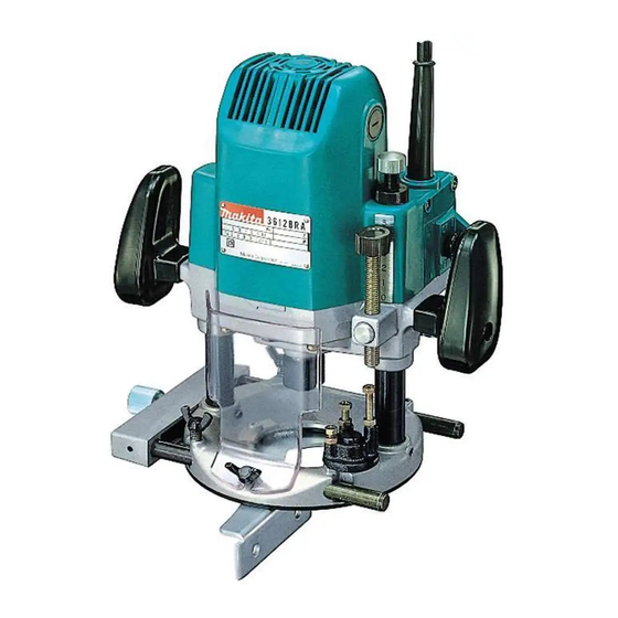
Makita 3612BR Instruction Manual
1/2" router
Hide thumbs
Also See for 3612BR:
- Instruction manual (13 pages) ,
- Instruction manual (16 pages) ,
- Instruction manual (32 pages)
Table of Contents
Advertisement
1/2"
MODEL 3 6 1 2 B R
1/2" MODEL 3 6 1 2 B R A
Equipped with electric brake
Collet chuck
capacity
1 i 2 "
INSTRUCTION MANUAL
-
Main body
No load speed
0 vera I I
Net
stroke
(RPM)
length
weight
2 8 7 m m
5.7 k g
11 1-5/16")
( 1 2 . 7
lbs)
~
_
_
~
~
~
-
.
_
_
_
_
_
.
~
~
~
~
~
_
_
_
~~
23,000
0
6 5 "
(0
~~
2-9/16")
DOUBLE
INSULATION
Advertisement
Table of Contents

Related Manuals for Makita 3612BR


Summary of Contents for Makita 3612BR
- Page 1 1/2" MODEL 3 6 1 2 B R 1/2" MODEL 3 6 1 2 B R A Equipped with electric brake INSTRUCTION MANUAL DOUBLE INSULATION Collet chuck 0 vera I I Main body No load speed capacity stroke (RPM) length weight 6 5 "...
- Page 2 IMPORTANT SAFETY INSTRUCTIONS (For All Tools) WARNING: WHEN USING ELECTRIC TOOLS, BASIC SAFETY PRECAUTIONS SHOULD ALWAYS BE FOLLOWED TO REDUCE THE RISK OF FIRE, ELECTRIC SHOCK, AND PERSONAL INJURY, INCLUDING THE FOLLOWING: READ ALL INSTRUCTIONS. KEEP WORK AREA CLEAN. Cluttered areas and benches invite injuries. CONSIDER WORK AREA ENVIRONMENT.
- Page 3 REMOVE ADJUSTING KEYS AND WRENCHES. Form habit of checking t o see that keys and adjusting wrenches are removed f r o m tool before turning 1 5 . AVOID UNINTENTIONAL STARTING. Don't carry tool with finger o n switch. Be sure switch is OFF when plugging in.
- Page 4 VOLTAGE WARNING: Before connecting the tool t o a power source (receptacle, outlet, etc.) be sure the voltage supplied is the same as that specified nameplate of the tool. A power source w i t h voltage greater than that specified for the tool can result in SERIOUS INJURY t o the user as well as damage t o TOOL.
- Page 5 Installing or removing router bit CAUTION Always be sure that the tool i s switched off and unplugged before installing or removing the bit. Insert the bit all the way into the collet cone and withdraw it very slightly (approx. mm;...
- Page 6 By turning the nylon nut, the upper limit of the tool body can be adjusted. When the tip of the bit is retracted more than re- quired in relation to the base plate surface, turn the nylon nut to lower the upper limit. CAUTION : Do not lower the nylon nut too low or the bit will protrude dangerously.
- Page 7 NOTE : Moving the tool forward too fast may cause poor quality cut, or damage to the or motor. Moving the tool forward too slowly may burn and mar the cut. The proper feed rate will depend on the bit size, the kind of workpiece and depth of cut. Before beginning the cut on the actual workpiece, it i s advisable to make a sample cut on a piece of scrap lumber.
- Page 8 Trimmer guide (Optional accessory) Trimming, curved cuts in veneers for fur- niture and the like can be done easily with the trimmer guide. The guide roller rides the curve and assures a fine cut. Install the trimmer guide on the guide holder with the wing bolt Tighten the (6).
- Page 9 Templet guide (Optional accessory) a sleeve The templet guide provides through which the bit passes, allowing use of router with templet patterns. To install the templet guide, loosen the plate Templet guide Base screws on the tool base, insert the templet guide and then tighten the screws Screw Secure the templet to the workpiece.
- Page 10 Brush holder cap brushes, insert the new ones and secure the brush holder caps. Screwdriver To maintain product SAFETY and RELIABILITY, repairs, any other maintenance or adjustment should be performed by Makita Authorized or Factory Service Centers, always using Makita replacement parts.
- Page 11 ACCESSORIES CAUTION : These accessories or attachments are recommended for with your Makita tool specified in this manual. The of any other accessories or attachments might present risk injury to persons. The accessories or attachments should be used only in the proper and intended manner.
- Page 12 Bits STRAIGHT Single Flute CARBIDE TIPPED PART NO. 733002-0A 1-1 I 2 2.314 733002-4A 1-114 1-318 2-718 HIGH SPEED STEEL PART NO. 733232-6A 1 I 8 5/16 1-118 1-518 S T R A I G H T Flute - I D + CARBIDE TIPPED PART NO.
- Page 13 VEINING -Single Flute SOLID CARBIDE PART NO. 733007-SA 3116 7132 1-1 I 4 1-1 12 ROUND NOSE CARBIDE TIPPED P A R T N O . 733008-2A 15/32 1-1 14 1-718 9116 1-114 733008-4A 11116 1-114 1 14 2-3/16 733008-6A 11/16 1-114 2-1 14...
- Page 14 DOVETAIL CARBIDE TIPPED PART NO 1-1/4 1 I 4 1 -7/8 733009-6A HIGH SPEED STEEL PART NO. 733239-6A 1 / 2 1 / 2 1 -3/8 1 I 4 STAGGER TOOTH CARBIDE TIPPED P A R T N O . 733007-0A 3 / 8 1.112...
- Page 15 BEADING CARBIDE TIPPED - Ball Bearing Pilot 7331 21 - 4 A 1-114 1-15/16 3/16 733121-6A 1-114 733121-8A 1~118 1-114 2-1/16 5 / 1 6 733122-0A 1-114 1-114 2-1/8 733122-2A 1 1 / 2 1114 2-114 REPLACEMENT BEARING NO. 733132-2A COVE CARBIDE TIPPED - Ball Bearing Pilot 733122-6A...
- Page 16 R O M A N OGEE CARBIDE TIPPED - Ball Bearing Pilot P A R T N O 733123-2A 15/32 1-1/4 5/32 733123 4A 1-318 21/32 1-1/4 2-1/8 REPLACEMENT BEARING - NO 733132-2A FLUSH T R I M M E R Self Piloting SOLID CARBIDE PART NO.
- Page 17 COMBINATION FLUSH/22" BEVEL TRIMMER 4 D C CARBIDE TIPPED PART NO 7331 28-6A 711 6 3/16 1-114 1-314 Self Piloting F L U T E FLUSH T R I M M E R ASSEMBLY SOLID CARBIDE CUTTER PART NO. 733129-2A 1-114 2-318 REPLACEMENT BEARING - NO.
- Page 18 F L U T E 22" B E V E L REPLACEMENT CUTTER SOLID CARBIDE P A R T N O . 733129-8A 7 /8 1 /4 FOR BEVEL TRIMMER ASSEMBLY NO. 733129-4A 114" REPLACEMENT ARBOR PART NO. 733131-2A 5 / 8 1-1/4 2-3/8 L A 4...
- Page 19 Feb-20--'92 1/2" ROUTER Model 3612BR Model 3612BRA Note: T h e s w i t c h a n d o t h e r p a r t c o n f i g u r a t i o n s...
- Page 20 & fre:ght prepaid, of Makita's Factdry A\thorized Selvtce Centers. If inspection shows the trouble is caused by defective workmanship material, Makita will repair (or at our option, replace) without charge. This Warranty does not apply where: repairs have been...