Table of Contents
Advertisement
Euphonix MADI Converters Manual
AM713 Analog to MADI, MA703 MADI to Analog
DM714 Digital to MADI, MD704 MADI to Digital
Euphonix Inc.
220 Portage Ave.
Palo Alto, California 94306
Phone:
650-855-0400
Fax:
650-855-0410
Web:
http://www.euphonix.com
e-mail:
info@euphonix.com
Document Revision: 2.1
Release Date: May, 2005
Part Number: 840-08416- 02
Advertisement
Table of Contents

Subscribe to Our Youtube Channel
Related Manuals for Euphonix MADI Converters


Summary of Contents for Euphonix MADI Converters
- Page 1 Euphonix MADI Converters Manual AM713 Analog to MADI, MA703 MADI to Analog DM714 Digital to MADI, MD704 MADI to Digital Document Revision: 2.1 Release Date: May, 2005 Part Number: 840-08416- 02 Euphonix Inc. 220 Portage Ave. Palo Alto, California 94306...
- Page 2 In the interest of continued product development, Euphonix Inc. reserves the right to make improvements in this manual and the products it describes at any time, without notice or obligation. System 5, S5, Max Air, PatchNet, eMix, EuCon, R-1, Audio Deck, Studio Hub are trademarks of Euphonix, Inc.
-
Page 3: Table Of Contents
Euphonix MADI Converters Operation Manual Table of Contents List of Figures ........................vi Chapter 1: Introduction ....................7 AM713/MA703 ..................7 DM714/MD704 ..................7 Power On Sequence...................8 Safety and Precautions ................8 1.4.1 220, 230, 240 VAC Operation ............8 Chapter 2: AM713 and MA703 Converters ............11... -
Page 4: List Of Figures
Euphonix MADI Converters Operation Manual List of Figures AM713 Front Panel ......................12 AM713 Rear Panel ......................14 MA703 Rear Panel ......................16 DM714 Front Panel ......................24 DM714 Rear Panel ......................26 MD704 Rear Panel ......................28 DM714 Female DB25 Connector ..................34 MD704 Female DB25 Connector ..................35... -
Page 5: Chapter 1: Introduction
Euphonix MADI Converters Operation Manual Chapter 1: Introduction AM713/MA703 The AM713 and MA703 converters provide MADI conversion to interface to/from analog equipment such as consoles, tape decks, microphone preamplifiers and other analog devices. Both converters are two rack spaces high and are housed in a stainless steel chassis with machined, heavy aluminum front panels. -
Page 6: Power On Sequence
Euphonix MADI Converters Operation Manual Introduction Power On Sequence We recommend powering up the converters only after verifying the presence of a val- id sync signal. After powering up the converters, the meter LEDs flash briefly and the Sample Rate and Sample Rate Source LEDs blink as the converter senses the incoming Sample Rate source and Sample Rate. - Page 7 Euphonix MADI Converters Operation Manual Introduction Power Cord Requirements The converters are supplied with North American IEC power cords. If this cord is changed to allow a different plug configuration, it is the responsibility of the user to se- lect an approved power cord with proper construction material, current capacity, flexi- bility, and strength characteristics.
- Page 8 Euphonix MADI Converters Operation Manual Introduction...
-
Page 9: Chapter 2: Am713 And Ma703 Converters
MADI and/or MADI-to-analog conversion is necessary (i.e., interfacing an analog tape deck to a digital mixer). When used with the Euphonix SH612 Studio Hub, this is a powerful conversion and MADI routing system that can be used to interface between an analog console and an otherwise all-digital facility (i.e., TV broadcast facility). -
Page 10: Am713/Ma703 Front Panel
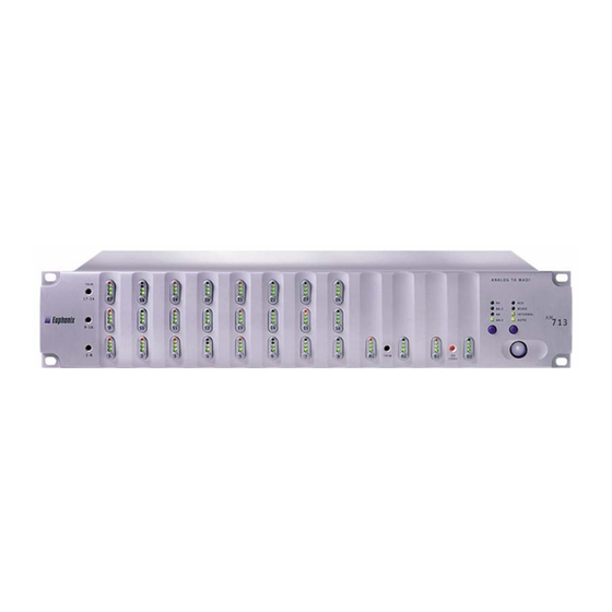
Euphonix MADI Converters Operation Manual AM713 and MA703 Converters AM713/MA703 Front Panel This section discusses both front panels and notes their few differences. Figure 2-1 AM713 Front Panel Signal Strength LEDs: Each of the 28 channels has a four-segment LED that repre- sents the following signal levels: -42 dB, -18 dB, -6 dB (green), -0.05 dB (red). - Page 11 Euphonix MADI Converters Operation Manual AM713 and MA703 Converters Manual Selection Buttons: The button below each Sample Rate LED row manually selects the sample rate. The AM713 also allows manual selection of the Sample Rate Source. Power Switch: On/Off switch.
-
Page 12: Am713 Rear Panel
Euphonix MADI Converters Operation Manual AM713 and MA703 Converters AM713 Rear Panel Figure 2-2 AM713 Rear Panel Input Voltage Selector: This red switch allows the unit to operate in either 110/115 VAC or 220/230/240 VAC environments. A fuse must also be changed for 220/230/240 VAC operation (see page 6). - Page 13 Euphonix MADI Converters Operation Manual AM713 and MA703 Converters MADI Out (BNC): Outputs the digital audio signal. • 1–24: Analog inputs • 25–26: Aux analog inputs • 27–28: Aux digital inputs NOTE: 28 channels are always transmitted; dual channels are not used.
-
Page 14: Ma703 Rear Panel
Euphonix MADI Converters Operation Manual AM713 and MA703 Converters MA703 Rear Panel Figure 2-3 MA703 Rear Panel Input Voltage Selector: This red switch sets the unit to either 110/115 VAC or 220/ 230/240 VAC environments. A fuse must also be changed for 220/230/240 VAC oper- ation (see page 6). - Page 15 Euphonix MADI Converters Operation Manual AM713 and MA703 Converters MADI In (BNC): Digital audio signal input. • 1–24: analog outputs • 25–26: aux analog outputs • 27–28: aux digital outputs...
-
Page 16: Synchronization
Euphonix MADI Converters Operation Manual AM713 and MA703 Converters Synchronization 2.6.1 AM713 The AM713’s Sample Rate is set externally by one of two source signals or internally by crystals and associated circuitry. The Sample Rate Source is determined automati- cally by the presence of signals when the AM713 is powered on. The order in which external signals are tested for presence is: AES, Word, Internal. -
Page 17: Specifications
Euphonix MADI Converters Operation Manual AM713 and MA703 Converters Specifications AM713 Performance Specifications Sync Sources AES, word clock, internal Sync Outputs AES thru and word clock out Sync Detection Auto or switched Internal Sample Rate 44.1, 48, 88.2, 96 kHz ±50 ppm Lock range ±300 ppm... - Page 18 MA703 Performance Specifications Sync Sources AES, word clock, MADI Sync Outputs AES thru and word clock out Sync Detection Auto or switched Internal Sample Rate 44.1, 48, 88.2, 96 kHz ±50 ppm Lock range ±300 ppm fine mode ±12% varispeed of 44.1 and 48 kHz custom mode Above 50 kHz, varispeed can adjust the nominal sample rate by -12 to +5% BNC 75 Ω...
- Page 19 Euphonix MADI Converters Operation Manual AM713 and MA703 Converters AM713/MA703 Technical Specifications Power Requirements 110/115 VAC or 220/230/240 VAC; 50 or 60 Hz Power Consumption 50 W ° Temperature of Operation 5–35 Dimensions Height: 3.5 in; Width: 19 in; Depth: 18.25 in; Weight: 17 lb...
- Page 20 Euphonix MADI Converters Operation Manual AM713 and MA703 Converters...
-
Page 21: Chapter 3: Dm714 And Md704 Converters
The analog inputs and outputs can be calibrated from the front panel of each unit. Applications The DM714 and MD704 can be used as 24-channel digital interfaces in a Euphonix digital system or other situations requiring digital to MADI conversion. These devices allow recording or transferring to/from digital devices that are not compatible with MADI but have an AES/EBU interface. -
Page 22: Dm 714/Md704 Front Panel
Euphonix MADI Converters Operation Manual DM714 and MD704 Converters DM 714/MD704 Front Panel This section discusses both front panels and notes their few differences. Figure 3-1 DM714 Front Panel Signal Strength LEDs: Each of the 28 channels has a four-segment LED that repre- sents the following signal levels: -42 dB, -18 dB, -6 dB (green), -.05 dB (red). - Page 23 Euphonix MADI Converters Operation Manual DM714 and MD704 Converters • AES: Sample Rate locked to AES Input. • Word: Sample Rate locked to Word Clock Input. • Internal (DM714 only): Sample Rate locked to its own internal crystal. • MADI (MD704 only): Sample Rate locked to MADI.
-
Page 24: Dm714 Rear Panel
Euphonix MADI Converters Operation Manual DM714 and MD704 Converters DM714 Rear Panel Figure 3-2 DM714 Rear Panel Input Voltage Selector: This red switch allows the unit to operate in either 110/ 115 VAC or 220/230/240 VAC environments. A fuse must also be changed for 220/ 230/240 VAC operation (see page 6). - Page 25 Euphonix MADI Converters Operation Manual DM714 and MD704 Converters Word Out (BNC): Outputs a Word clock signal synchronized to the Sample Rate Source. In the presence of an external Word clock input, this connector provides a re- generated version of that input signal. Without an external sample rate source, this con- nector outputs the internally generated clock signal.
-
Page 26: Md704 Rear Panel
Euphonix MADI Converters Operation Manual DM714 and MD704 Converters MD704 Rear Panel Figure 3-3 MD704 Rear Panel Input Voltage Selector: This red switch sets the unit to either 110/115 VAC or 220/ 230/240 VAC environments. A fuse must also be changed for 220/230/240 VAC oper- ation (see page 6). - Page 27 Euphonix MADI Converters Operation Manual DM714 and MD704 Converters MADI In (BNC): Digital audio signal input. • 1–24: main digital outputs • 25–26: aux analog outputs • 27–28: aux digital outputs Bit-Depth Reduction: Sets the resolution to 16, 20, or 24 bits for the main AES/EBU...
-
Page 28: Synchronization
Euphonix MADI Converters Operation Manual DM714 and MD704 Converters Synchronization 3.6.1 DM714 The DM714’s Sample Rate is set externally by one of two source signals or internally by crystals and associated circuitry. The Sample Rate Source is determined automati- cally by the presence of signals when the DM714 is powered on. The order in which external signals are tested for presence is: AES, Word, Internal. -
Page 29: Specifications
Euphonix MADI Converters Operation Manual DM714 and MD704 Converters Specifications DM714 Performance Specifications Sync Sources AES, word clock, internal Sync Outputs AES thru and word clock out Sync Detection Auto or switched Internal Sample Rate 44.1, 48, 88.2, 96 kHz ±50 ppm Lock range ±300 ppm... - Page 30 Euphonix MADI Converters Operation Manual DM714 and MD704 Converters MD704 Performance Specifications Sync Sources AES, word clock, internal Sync Outputs AES thru and word clock out Sync Detection Auto or switched Internal Sample Rate 44.1, 48, 88.2, 96 kHz ±50 ppm Lock range ±300 ppm...
- Page 31 Euphonix MADI Converters Operation Manual DM714 and MD704 Converters AM713/MA703 Technical Specifications Power Requirements 110/115 VAC or 220/230/240 VAC; 50 or 60 Hz Power Consumption 25 W ° Temperature of Operation 5–35 Dimensions Height: 3.5 in; Width: 19 in; Depth: 18.25 in; Weight: 17 lb...
-
Page 32: Dm714: Pinout For Female Db25 Connector
Euphonix MADI Converters Operation Manual DM714 and MD704 Converters DM714: Pinout for Female DB25 Connector Figure 3-4 DM714 Female DB25 Connector Table 3-1 DM714 DB25 Pinout Pin Number Signal 1–6 no connect Digital in 7/8 + (or 15/16, 23/24 +) -
Page 33: Md704: Pinout For Female Db25 Connector
Euphonix MADI Converters Operation Manual DM714 and MD704 Converters MD704: Pinout for Female DB25 Connector Figure 3-5 MD704 Female DB25 Connector Table 3-2 MD704 DB25 Pinout Signal Number Digital out 7/8 + (or 15/16, 23/24 +) Digital out 5/6 - (or 13/14, 21/22 -) - Page 34 Euphonix MADI Converters Operation Manual DM714 and MD704 Converters...
Need help?
Do you have a question about the MADI Converters and is the answer not in the manual?
Questions and answers