Advertisement
Quick Links
Advertisement

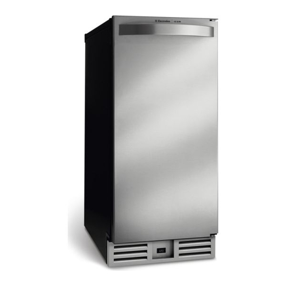
Related Manuals for Electrolux E15IM60EBS0


Summary of Contents for Electrolux E15IM60EBS0
- Page 1 Care Guide G u_a de Uso y Cuidado d'utilJsation Guide d'entretien...
- Page 2 Thank you for choosing EJectrolux, the new premium brand in home appliances. This Use & Care Guide is part of our commitment to customer satisfaction product quality throughout the service life of your new ice maker. We view your purchase as the beginning of a relationship.
- Page 3 Warranty coverage begins at the time your Ebctrolux ice maker was purchased. Phase record the purchase date of your Electrolux unit and your dealer's name, address and tebphone number. Purchase Date Eiectrolux Model Number Electrolux Serial Number Dealer Name...
- Page 4 TABLE OIF' C ONN Finding Information ........... 2 Built-in Installation .......... 20 PleaseReadAndSaveThis Guide ....2 Start-up .............. MakeA RecordForQuickReference....2 WarrantyRegistration Card....... 3 Normal Operation ..........22 Questions? ............3 iceCubeThickness......... 22 TableOfContents..........4 iceDispsenser OperationandCare ....23 Safety ..............Maintenance ............25 Important SafetyInstructions ......
- Page 5 £NT S£F Y IINS U _ONS Safety Precautions Do not attempt to install or operate your unit until you have read the safety precautions in this manual. Safety items throughout this manual are labeled with a Danger, Warning or Caution based on the risk type.
- Page 6 Generam Precautions...
- Page 7 II N STAII,,,,,,,,,,_,,,,,,,,,,AT_ON D_MENS_ONS (81) 34 = !/8" (86.7) FULL RETRACT WATER HEIGHT VALVE "_o WATER DRAIN WATER 21 =3/4" OUTLET (55.2) Figure 1...
- Page 8 THE £1N Model E151M60E can be installed using a gravity drain or can use a factory installed or equivalent drain pump. Follow these guidelines when installing drain lines to prevent water from flowing back into the ice maker storage bin and/or potentially flowing onto the floor causing water damage:...
- Page 9 Make certain the unit is not plugged into an electrical outlet. BACK Carefully push the power cord grommet through the hole PANEL in the back panel. See Figure DRAIN Remove 12 screws and back panel. FiTTiNG Check that the clamps and hose connections are tight at POWER...
- Page 10 CONNE £ DR£11N P UMP If a gravity drain connection is not availabb, and you have not purchased E15JM60E with factory installed pump, we strongly recommend the use of the Eiectrolux EJMP60 drain pump. The Eiectrolux EIMP60 drain pump is available through your Dealer, or direct from Ebctrolux with compbte...
- Page 11 IP PAB NG T SITE Position the unit on a flat, level surface, capable of supporting the entire weight of the unit. Remember that the unit will be significantly heavier once it is fully loaded. The surrounding air temperature must be at least 50°F (10°C) but must not exceed 110°F (43°C).
- Page 12 Install and connect the water supply line. See Connecting the Water Supply for installation requirements. Position the unit to allow free air flow through front grille (see Figure Wipe out inside of unit with a damp cloth. 0" CLEARANCE NEEDED UL124A Figure 4 WALL...
- Page 13 Whenconnectingthe water supply,follow theseguidelines: Reviewthe bcaU plumbingcodesbeforeyou instaUl the unit. The waterpressureshouldbe between20 and120psi. Makecertaina SHUT-OFF VALVEis instaUled i n the 1/4 inchwatersupplyHne. Connectsufficienttubingto the unitto allow the unitto be movedfor cleaningand servicing.However,makecertainthatthe WATER tubing is not pinchedor damagedduring CONNECTmON installation.
- Page 14 Locate the compression fitting and ferrule packed in the Figure8 unit. Slide the compression fitting and ferrule over the 1/4 inch water supply line. Do not use thread sealing compound or tape. Using two wrenches, tighten the compression fitting on the supply line (see Figure Carefully bend the water supply line into position and connect...
- Page 15 IILEV UNiT Use a ReveU to check the ReveUness of the ice maker from front to back and from side to side (see Figure 11). tf the ice maker is not bveU, adjust the feet on the corners of the unit as necessary (see Figure 12).
- Page 16 REVERSING THE BOOR(SOMEMO ILLS} AH EbctroUux units may be bft or right hand opening. The door opening is easily reversed by moving the hinge hard-ware to the opposite side (see Figure 13). To reverse the door: Remove top hinge screw pin (7/64" AUUenwrench) from cabinet (see Figure 14).
- Page 17 HINGE _"_ SCREW Remove top hinge (3 screws), reinstall hinge screw pin, and remount on opposite side BOTTOM (see Figure 17). Remove the two door cioser inserts from the existing bottom Figure 17 hinge and instali as shown on the new bottom hinge (see Figure 18).
- Page 18 £DJUST NG THEOB Your door is aligned at the factory before shipment. OccasionaU re=adjustment be necessary, especially if an overlay paneU is installed. The following procedure will correct for up to 1/4" alignment. The door shouUd never be flush with the top of the cabinet. Even when bveU, the top edge of the door wiIR be 1/8"...
- Page 19 tf door edge opposite the Nnges needs to move up, move plate toward outside of door. tf door edge needs to move down, move plate toward inside of door (see Figure 23). Repeat until top edge of door is MOUNTING NOTCH parallel with top of cabinet and tighten...
- Page 20 £ Your Electrolux product has been designed for either free-standing or built4n installation. When built=in, your ice maker does not require additional air space for top, sides or rear. However, the front grille must NOT be obstructed. Built-in Cabinet Dimensions...
- Page 21 IINmAL,,,,, A Once installation and leveling is complete, the unit is ready for initial start-up operation. Your unit is shipped in the OFF position, however, you may turn it ON/ OFF using the cycle selector switch located in the access panel above the grille (see Figure 26).
- Page 22 Because of this ice making technology, clear ice cubes differ significantly from regular ice cubes. Differences illustrated in Figure Dimpieso Electrolux clear ice cubes have "dimples" on one side from the Figure 27 cascading water process.
- Page 23 liCEDISPENSER OPERATION & CARE The be cube thbkness control is factory set for best overall performance. factory setting is designed maintain an be bridge of Figure 28 approximately 1/16" to 1/8" under BRIDGE BRIDGE normal conditions resulting in a TOO THIN THICK 1/16"...
- Page 24 Locate the ice cube thickness adjustment dial on the control board (see Figure 30). Turn the dial clockwise (+ number) or counterclockwise (- number) to thin the ice bridge. Figure 30 DIAL IS FACTORY SET AT"O" ICE CUBE THICKNESS ADJUSTMENT DIAL !!_i_ i!i!_i_i!ii!_i_!_!_i_i!!i!_i!;_i_i!_!i!i!i_!_ !iiiii!iiii...
- Page 25 SPECiAl,,,,,,,,,, CONSDERATIONS For best performance, keep the unit out of direct sunlight. Turn the unit OFF and dispose of any be cubes if the unit will not be used for 5 days or more. Prop door open to allow for air circulation and prevent mold and mildew.
- Page 26 DO NOT CLEAN WITH STEEL WOOL PADS. ® DO NOT USE CLEANERS THATARE NOT SPECIFICALLY INTENDED STAINLESS STEEL (this includes glass, tile and counter cleansers). tf any surface discolors or rusting appears, clean it quickly with Bon-Ami Barkeepers Friend Cleanser and a non-abrasive cloth.
- Page 27 CondenserCleaning-- Every3 Months To maintain operational efficiency, clean the condenser every three months (depending on environmental conditions, more or less frequent cleaning may be necessary). To remove and replace the grille for access to the condenser fins follow this procedure (see Figure 32):...
- Page 28 Sdf Cleaning-- Every6 Months To maintain operational efficiency, clean the unit every six months (depending water conditions more or lees frequent cleaning may be necessary), if the ice maker requires more frequent cleaning, consult a qualified plumber to test the water quality and recommend appropriate treatment.
- Page 29 (see Figure 34).The water inthe reservoirwill flow downthe drain. Replacethe overflowtube afterall ofthe waterhas drainedfromthe reservoir. Movethe cycleselectorswitchto the CLNposition. Whenwaterbeginsto flow overthe evaporator (approximately 3 minutes),addonepackageof Electrolux ice MacNneCleanerto the waterreservoir. Reinstallinsidefrontcover. UL209a Whenthe self-cleaningprocessstops (approximately 45 Figure 34 minutes)it maybe desirableto cleanthe storagebinat tMstime (seeInterior Cleaning).
- Page 30 DBABNBNG IB:'":'OR NON@SE If the unit is to be stored, moved or not used for extended periods, it will be necessary to drain the system of water. Disconnect power from the unit. Remove ice from the storage bin. Shut off water supply at the main water source. Disconnect the inlet and outlet lines to the water valve and allow them to drain.
- Page 31 BEFOREYOU CALL FORSERVICE tf the unit appears to be malfunctioning, read through Normal Operation first. If the problem persbts, check the Troubleshooting Guide. Locate the problem in the guide and refer to the cause and its remedy before calling for servbe. The problem could be sometNng very simpb...
- Page 32 Troubleshooting - What to check when problems occur Problem Possible Cause Remedy Poor icequality(softor unclear). • Poorincomingwaterquality. • Consulta qualifiedplumberto test the water qualityand recommend appropriate treatment. • Ice-making systemis dirty. • Rununitthreughautomaticcleancycle.See Maintenance. • Lowwater level. Unitproducesshallowor • Checkto see thatoverflowtube isfullyseated. incomplete cubes,orthe icefill •...
- Page 33 Theconsumershallpay for such servicecalls. 3. Damages causedby services performedby servicersother than ElectroluxHome Products,Inc., ElectroluxCanada Corp., or its authorizedservicers; use of parts other than genuine Electrolux Home Products parts; obtainedfrom personsotherthan suchservicers;or externalcausessuch asabuse, misuse,inadequatepowersupply or acts of God. 4. Productswith originalserial numbersthat have beenremovedor alteredand cannotbe readilydetermined.