
Related Manuals for Ohlins CANNONDALE FG 9910

Summary of Contents for Ohlins CANNONDALE FG 9910
-
Page 1: Owners Manual
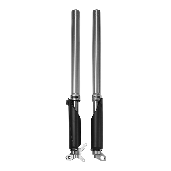
Owners manual Öhlins motocross front forks FG 9910 Cannondale Including: Setting up your bike Fine-tuning Service the fork Trouble shooting Technical info Spare parts & tools Traction, handling, comfort and safety... -
Page 2: Table Of Contents
Öhlins Contents Safety signals motocross Safety signals ......... 2 Important information concerning Introduction ........3 safety is distinguished in this manual front forks Design ..........3 by the following notations FG 9910 Before you start ......3 Kit content ........3 Cannondale The Safety alert symbol means: Marking .......... -
Page 3: Introduction
oil) that work together with the “real“ Introduction Marking spring. You adjust the air-spring by raising or lowering the oil level in the All Öhlins front forks are marked. Öhlins Racing congratulates you on legs. You will find the part number on the your choice of front fork for your By using different combinations of inside of the fork bottom. -
Page 4: Recommended Settings
ences, between the Öhlins recom- Mounting instructions Compression mended settings and the settings you achieve, may occur. Therefore, it is adjuster WARNING always wise to start the setting up by checking! 1. It is advisable to have an Öhlins The sag effects not just only the dealer or a qualified mechanic to fit suspension but also the rake of the your front fork kit. -
Page 5: Checking Rear Sag
Setting up the bike Checking sag and ride height. Front sag: A - B = 30 10 mm. Front ride height: A - C = 50 10 mm. Rear sag: A - B = 30 10 mm. Rear ride height: A - C = 100 10 mm. -
Page 6: Making Adjustments
Air spring Oil level Oil level 100 mm Oil level 110 mm Oil level 120 mm Oil level 130 mm A change in oil Oil level is 5 0 0 level will effect measured from the damping the top of the 4 5 0 forces, not in the outer leg, with... -
Page 7: Trouble Shooting
General handling set-up handle smaller bumps. soft during the entire wheel travel. Damping force not progressive Spring too soft, compression damp- Front end falls into the curves enough. ing too low. (over-steering) especially in sand. Increase the oil level. Increase the compression Steep front fork angle. -
Page 8: Preload Adjustment
Preload adjustment Put the bike on a stand and loosen the screws in the fork top crown that hold the fork legs. NOTE On most MX-bikes you have to take of the handle bar before you can unscrew the top cap. Unscrew the top cap, use a 24 mm wrench. -
Page 9: Changing Springs
Changing springs NOTE Closing the compression- and Loosen the screws that hold the rebound valves will keep the the fork legs in the upper fork damper rod extended making it crown. easier to install the new spring. With the fork leg still tightened Pull out the damper rod as far in the lower fork crown unscrew as possible. -
Page 10: Dismantling The Front Fork
Dismantling Perform steps a-d "Changing springs" on page 9. Loosen the bush head, on top of the cartridge tube, with tool 1797-01. Lift up the damper rod assem- bly and drain the oil. Pull up the scraper with a screwdriver, release and re- move the circlip. -
Page 11: Assembly Of The Front Fork
Remove the seals and bush- Assembling ings and replace them with new ones. Apply a thin layer of Öhlins green grease (148-01) on the scraper ring and on the sealing surface of the fork seal. Mount the scraper, circlip, fork seal, support ring and the bushings separated by the sleeve on the inner steel leg. - Page 12 Notes Fasten the fork leg, at the fork bottom, with soft jaws in a vice. Install the compression valve assembly in the fork bottom. Tightening torque 45 Nm. Apply some front fork oil on the outer surface of the inner leg, and push the outer leg up and down a few times.
-
Page 13: Service Tools
Service tools Pos. Part No. Description 1799-02 Bushing/seal mounting tool 0786-03 Inner tube tool 1797-01 Tool-cylinder tube lid 0787-03 Cylinder tube tool (cartridge) 1702-02 Bushing remover tool Technical specifications Rebound and compression adjustment Refer to mounting instruction for set-up data. Maximum open rebound and compression valve: 20 clicks. -
Page 14: Spare Parts
Spare parts Pos. Part No. Pcs. Description Type/remarks 02338-01 01050-01 Screw 00338-59 O-ring 02306-02 End cap 00438-17 O-ring 02337-01 Spring support 02319-01 Spring washer see spec. card Spring preload 02328-39 Spring see spec. card Spring 02324-02 Outer tube 02332-03 Sticker 00329-02 Circlip 02021-01... - Page 15 Spare parts Pos. Part No. Pcs. Description Type/remarks 01473-02 Circlip 00338-53 O-ring 02321-02 Adjustment screw 01248-01 Spring 00884-04 Ball 02366-12 Adjustment rod 00338-76 O-ring 02301-03 Needle housing 02302-03 Guide sleeve 02303-01 Sleeve 02304-01 Hydraulic stop 00131-05 Circlip 01499-01 Circlip 02305-03 Cylinder tube cap 02059-01 Bushing holder...
- Page 16 Traction, handling, comfort and safety Öhlins Racing AB, Box 722, S-194 27 Upplands Väsby, Sweden. Phone +46 8 590 025 00, fax +46 8 590 025 80. E-mail: info@ohlins.se...
Need help?
Do you have a question about the CANNONDALE FG 9910 and is the answer not in the manual?
Questions and answers