Table of Contents
Advertisement
Save This Manual For
Future Reference
MODEL NO.
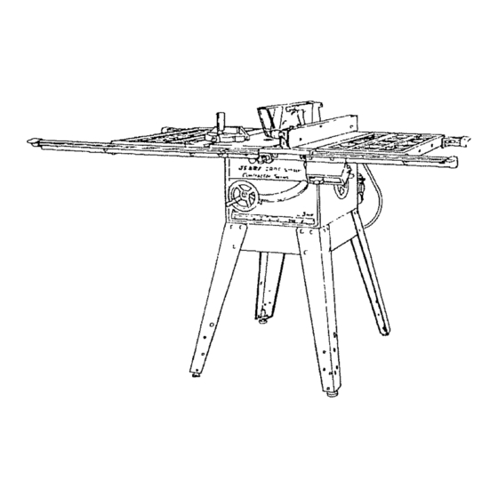
113=29884
SAW WITH LEGS
TWO CAST IRON
TABLE EXTENSIONS
MOTOR AND
QUICK RELEASE
RIP FENCE
Sedal
Number
Model and serlQI num_:x_rmay
be fotr_
at 1he rlghf-I'_nd
side of the
bose.
You should r_ord
both model
and
sedal number
In a safe
place for future use.
FOR YOUR
SAFETY:
READ ALL
INSTRUCTIONS
CAREFULLY.
CRRFTSMRH
10" Belt Drive Saw
• assembly
= operating
• repair parts
_,,
J
_.
Sold by SEARS,
ROEBUCK
AND CO., Hoffman
Estates,
IL. 60179
U.S.A.
Part No SP5624
Printed in U S A
J
Advertisement
Table of Contents

Related Manuals for Craftsman Contractor 113.29884


Summary of Contents for Craftsman Contractor 113.29884
- Page 1 Save This Manual For Future Reference MODEL NO. 113=29884 SAW WITH LEGS TWO CAST IRON TABLE EXTENSIONS MOTOR AND QUICK RELEASE RIP FENCE CRRFTSMRH Sedal Number Model and serlQI num_:x_rmay be fotr_ at 1he rlghf-I'_nd side of the bose. You should r_ord both model sedal number In a safe...
-
Page 2: Safety Instructions
if within one year from the data of purchase, this Craftsmen Table Saw fails due to a defect in WARRANTY SERVICE IS AVAILABLE BY SIMPLY CONTACTING THE NEAREST SEARS SERVICE CENTER/DEPARTMENT THROUGHOUT THE UNITED STATES. THIS WARRANTY APPLIES ONLY WHRLE THIS PRODUCTIS USED IN THE UNITED STATES. - Page 3 E. REMOVEADJUSTING KEYSANDWRENCHES. 1. Do not wear loose clothing, gloves, neckties or Form habit of checking for and removing keys and jewelry (rings, wristwatches). They can get adjusting wrenches from tool before turning it on. caught and draw you into moving parts. F, To avoid injury from jams, slips or thrown pieces 2.
-
Page 4: Additional Instructions For Rip Type Cuts
to tip when not held down to the table top. 2. Make sure the top of the arbor or cutting toot tu ms NEVER use another person as a substitute toward the front of the saw. for a table extension, oras additional support 3. -
Page 5: Additiona_ Instructions For Cross Cut Type Cuts
BEFORE STARllNG 3. Use jigs or fixtures to help hold any piece too sina!! to extend across the full length of the Miter Gauge face 1. To avoid kickbacks and slips into the blade, make during the cut. This lets you propedy hold the Miter sure the Rip Fence is parallel to the sawblade. -
Page 6: Motor Specifications And Electrical Requirements
glossary of terms for woodworking Ripping ThrOw-Back A cutting operation along the length of the workpiece. Throwing of pieces in a manner similar to a kickback. Revolutions Per Minute (RPM) Thru-Sawlng Thenumber of turns completed by a spinning object in Any cutting operation where the blade extends com- one minute. -
Page 7: Changing Motor Voltage
b. The movable links pivot on the center most screv_,_ - WARNING: Avoid eJectric shock, if the outlet you After links have been correctly positioned, be SL_ r_ are piannlng to use for this saw Is of the two prong type, DO NOT REMOVE OR ALTER THE GROUND- to tighten these screws to insure a good etectdc _ connection. -
Page 8: Motor Thermal Overload Protector
Motor Thermal Overload Protector breakers may result if: a. MOTOR IS OVERLOADED - Overloading can IMPORTANT: To avoid motor damage, this motor should occur if you feed too rapidly or if saw is misaligned be blown out orvacuumed frequently to prevent sawdust buildup which will interfere with normal motor ventilation. -
Page 9: Table Of Contents
CONTENTS Miter Gauge ............Warranty ..............BBade Guard ............37" Safety instructions for Table Saw ......2 "]'able Insert ............3"7 Additional Instructions for Rip Type Cuts ....4 Removing and Instal{ing Sawblade ..... Additiona_ Instructions for Cross Cut Type Cuts ...5 Exact-I-Cut ........ - Page 10 WARNING 8voUChes Separate all parts from packing materials and check each one with the illustrationand the list of Loose Parts use gasoline, naptha or smmllar highly volatile : TO _h hazard, never to make certain all items are accounted for, before solvent.
- Page 11 Bag of Loose Parts (containing the following items) Switch Assembly ..Hand Wheel ....Micro Adjust Knob Assembly ..Bag of Loose Parts ....© Bag of Loose Parts (containing the following items) Leveling Foot 3/8 ........... Hex Jam Nut 3/8-16 ........"Y Truss Head Screw, 1/4-20 x 1/2 ....
- Page 12 Guard Support ..........Drive Pulley ............Grip Notch Belt 1/2 x 42 ........Arbor Wrench............ Spreader Support ..........Protective Cap ........... Bracket .............. Thumb Screw 5/7 6-18 x 1 ......... 1 Fence Guide Bar SPacer ........6 Wire Tie ......Bag of Loose Parts ..........
-
Page 13: Checking Table Insed
ASSEMBLY Before mounting the saw on legs or a stand or a bench, the Table Insert and Blade Squareness must be checked at this time. UNSTALLING HANDWHEELS 1. Slide theelevation handwheel onto itsshaft. Line ELEVATION HANDWHEEI up the fiat spot on the shaft with the set screw in the handwheeL Using a hex "L"... -
Page 14: Checking Blade Squareness To Table
CHECKING BLADE SQUARENESS TABLE IMPORTANT: BLADE must be SQUARE {90 °) to TABLE, in order to proceed wilh assembly, MAKE SURE SQUARE 1. Turn ELEVATION handwheel clockwise unti! !S NOT TOUCHING TIP OF TOOTH blade is up as high as it will go. 2. -
Page 15: Mounting Saw
MOUNTING 1. From among the loose parts, find the following hardware: 4 Hex Head Screws, 5/16-18 x 1-1/4 in. long. HEX HEAD SCREW 5/16 - 18 4 Hex Nuts, 5/16-18 (approx. dia. of hole 5/16 in.) HEX NUT 4 Lockwashers, 5/16 in. -
Page 16: Attaching And Assembling Table Extensions
ATTACHING AND ASSEMBLING TABLE EXTENSIONS HEY, HEAD SCREW FLAT WASHER From among loose parts find the following hardware: (Quantity indicated is for 2 extensions) Description Qty. Hal. Screw 5/16-18 x 1-1/4 ..5/16 IN HEX NUT Flat Washer (Dia of Hole 11/32) .. -
Page 17: Mounting Switch
MOUNTING SWITCH 1, From among loose parts find the following: 2 Hex Head Screws, 5/16-18 x 5/8 in. long 2 External 5/!6" Lockwashers 2 Hex Nuts, 5/t6-18 5/8 IN 5/t6 IN EXTERNAL 5/16 IN HEX HD SCREW LOCKWASHER HEX NUT JAM NUT 5/16-18 2. -
Page 18: Installing Left Front Rip Fence
6TH HOLE SPACER 4. Insert a 1-114 inch long screw through a flat washer _-'_-_, -_._t_--_ and the SECOND hole IN THE FRONT BAR as illus- _-_ _ "%'--- ,_:_!'_ _"_"_ trated, insert a 1-I/4 nch ong screw throuah a washer "_,_;_ _';v_""... -
Page 19: Installing Rear Rip Fence Guide Bars
5. Turn front bar end for end and insert two of the bolts through holes on teft side of front edge on saw table. The third screw is inserted through the bracket installed earlier 6. Install lockwashers and nuts on bolts. DO NOT SCREW NUTS ON ALL THE WAY, j ust get them started on the screws. - Page 20 EXTERNAL LOCKWASHER H_x_T 6. Turn thefenceguidebar e ndforendandinsert t wo ofthe 1inchlongscrews through thetwoholesin HEXNUT\_. theleftrearedgeofthe table. I nsert t heother3/4 inchlongscrew through thebracket. Install a lock- "_ \ .,/WASHER washer andnutonbolts. D ONOT SCREW NUTS ON WASHER .-"-'_ _' LEFT REAR _"...
-
Page 21: Adjusting Rip Fence Guide Bars
ADJUSTING RIP FENCE GUIDE BARS WARNING: Mlsadjusted ience guSde bars can mBsalig n the fence. A misaglgned fence can cause kickbacks jams. You could be cut or hit. Proper_y adjust fence guide bars before using 1. From among the loose parts find the following hard- ware: VERY THIN SHIM WASHER... - Page 22 VIEW FROM TOP OF SAW 4. The guide bar you stacked washers against step 3 must now be removed so stacks of washers be installed. remove nuts Iockwashers from tWO screws that hold the guide © bar to front edge of table. Pull guide bar away...
- Page 23 8 THICKNESS OF PAPER 9. Move the rip fence to the right so it is even with the outside edge of the extension (as viewed from front of saw) and put the two stacks of paper under front and rear of the rip fence with the paper setting on the front and rear edge of the table_ 10.
-
Page 24: Assembling Rip Fence
19. Using a tape rule measure distances from rear cage VIEW FROM TOP OF SAW of back rip fence guide bars to front edge of lront rip fence guide bars. Make measurements at each miter gauge grooveand at the end of each extension. A!I tour measurements must be the same. -
Page 25: Rip Fence Self Aligning Pad Adjustment
A. Adjusting Fence Racks 1. Look under front fer_ce guide bars. The racks should be approximately 1-1/8 inch apa_ between the ends of both racks as ilJustrated. 2. Adjust the racks by loosening t he lout screws that mount each rack. Stide both racks to the 1-1/8 inch measurement and tighten screws. -
Page 26: Rip Fence Lock Lever Adjustment
3. If fence does not spring back, the spring pressure must be INCREASED. To do so: A. Loosen the screws. B. Move spring slightly toward front of fence. 4, If fence does not slide easily along the bars the pressure of the spring can be REDUCED. A. - Page 27 mNSTALLmNG MEASURING TAPES -"-:- - .._ ÷:-÷-4-_t=::T:=F._T-_-_ 1. From the !oose parts find: 2 Measuring Tapes 2. Place rip fence on saw table to the right side of the blade. 3. Using a tape ruie measure six inches out from the right side of the btade.
- Page 28 8. Remove rip fence from saw. Remove measuring tapefrom saw but keep it separate from other measuring tape. It must later be attached to this same rip fence guide bar. At the left end and rig ht 3/8 INCH FROM end of right rip fence guide bar.
-
Page 29: Installing Blade Guard
iNSTALLiNG BLADE GUARD 1. From among the loose parts, find 2 Hex Head Screws, 1/4-20 x 5/8 in. long HEX NUT 3 Hex Head Screws, 5/16-18 x 5/8 in. long 2 Hex Head Screws, 5/16-18 x 1 in. long °"{::_: 2jZ,j:::4.4;: 2 Hex Nuts, 1/4-20 (approx. - Page 30 SQUARE 7_ S_ide SPREADER ROD into BLADE GUARD SUP- PORT until end of ROD is even with edge of SUP- PORT...Tighten Hex Head Screw in support. 8. Attach SPREADER to SPREADER SUPPORT that the edge of the spreader is even with the edge of the spreader support...tighten screws.
-
Page 31: Positioning Motor On Motor Mounting Base
FOLDED PAPER Place RiP FENCE on table_ ;REW CAREFULLY move it aga nat b_ade so that it is paraS. ,WRENCH iel to the biade, and just TOUCH ES tips of saw teeth ...tighten RiP FENCE LOCK LEVER° 17. insert folded paper between SPREADER... -
Page 32: Mounting The Motor
MOUNTING THE MOTOR 1. From among the loose parts, find the following hardware: CARRIAGE BOLT 4 Carriage Bolts, 5/16-18 x 3/4 in. long 4 Hex Nuts, 5/16-18 (approx. dia. of hole 5/16 in.) 5/16" HEX NUT 4 Lockwashers, 5/16 in. External Type (approx. dia. -
Page 33: Installing Belt Guard
8. Lower the blade...install belt on saw pulley motor pulley. 9. Sight along edges of both pulleys and move motor pulley so that belt is parallel to the edges of both pulleys.. ,tighten the set screw in the motor pulley. 10. - Page 34 2. Remove the belt and motor pulley. 3. Screwsfurnished with guard are"self-threading" screw them into holes in BELT GUARD SUPPORT BRACKET to cut threads, then remove them. BELT GUARD 4 Position BELT GUARD SUPPORT BRACKET and BELT GUARD SUPPORT as shown PPORT BRACKET install the screws.,...
-
Page 35: Motor Connections
MOTOR CONNECTIONS WARNING: For your own safety, never connect plug to power source out_et until a_ assembly steps are compgeted. 1. Open motor connector box cover 8ocated on side of BLACK WIRE TO SPADE TERMINAL BESIDE motor using a fiat blade screwdriver. COPPER POST GREEN WIRE nect anythlng... - Page 36 BLANK PAGE...
- Page 37 BLANK PAGE...
- Page 38 NEVER OPERATE SAW WITHOUT PROPER INSERT IN PLACE. USE THE SAW BLADE INSERT WHEN SAWING. USE THE COiVlBINATION DADO MOLDING INSERT WHEN DADOING MOLDING. REMOVING AND INSTALLING SAWBLADE. WARNING: To avoid injury from accidental ARBOR start, turn switch "OFF" end remove plug WRENCH from power sourceoutBet before removing or Instaiilng sawblade.
-
Page 39: Basic Saw Operation
When cutting the workpiece, line up mark on workpiece with line on Exact-i-Cut. 11 MICRO-ADJUST RIP FENCE . . . allows operator to accurately adjust the rip fence using only one hand. To move the fence push in on the micro-adjust knob and rotate the knob. -
Page 40: Auxiliary Fence/Work Support
3/4 PLYWOOD 3-1/2 AUXILIARY FENCE/WORK SUPPORT Make one using a piece of 3/8 inch and 3/4 inch plywood. THIS FACE THIS Fasten together with glue and flat head woodscrews. EDGE MUST BE PARALLEL Tighten the screws sa the flat head is even with the pLYWOOD bottom of the wood. - Page 41 Any power saw can throw foreign objects into 4. Choose and inspect your cutting tool care- the eyes. This can cause permanent fully. damage. Wear safety goggles (not glasses) a. To avoid cutting too_ failure thrown that comply with ANSI Z87.1 (shown on pack- shrapnel (broken pieces...
- Page 42 - Never confine the piece being cut off. That 1. Before actually cutting with the saw, watch it while it is, the piece NOT against the fence, miter runs for a short while. If it makes an unfamilar noise gauge or fixture. Never hold it, clamp it, or vibrates excessively, stop immediately.
-
Page 43: Using The Miter Gauge
USING THE M TER GAUGE THE MgTER GAUGE IS USED WHEN CROSSCUT- - An auxiliary wood facing attached to the miter gauge can help prevent workpiece twisting TING, MITER CUTTBNG, BEVEL CUTTING, COM- throwbacks. Attach it to the holes provided. POUND MITER CUTTING, DADOI_NG and when... -
Page 44: Repetitive Cutting
When cutting long workpieces, invert AUXILIARY FENCE/ WORK SUPPORT and Position it on top of the guide bars to support the workpiece as near to the end as possible. if this does not adequately support the workp_ece, _,ou can make a simple support by clamping a piece of ply- wood to a sawhorse. -
Page 45: Miter Cutting
1. NEVER USE THE RIP FENCE AS A LENGTH STOP BLOCK _ BECAUSE THE CUT OFF PIECE COULD BIND BE]3NEEN THE FENCE AND THE BLADE CAUS- ING A KICKBACK. 2, When making repetitive cuts shorter than 6 in., clamp a b_ockof wood 2 in, _ongto the tabte to act as a _ength stop. -
Page 46: Using The R_P Fence
USING THE RiP FENCE KERFS ABOUT RIPPING, BEVEL RIPPING, PLOUGHING, MOLDING, 5/16" APART RESAWING AND RABBETING are performed using the RIP FENCE together with the AUXILIARY FENCE/ 4-1/2" WORK SUPPORT, PUSH STICK OR PUSH BLOCK. / WARNING: For your own safety, always observe I i the fOllowing safety precautlo_ in addiUon to the Before starting... - Page 47 USUNG FEATHERBOARDS FOR THRU- SAWRNG Featherboards are not employed for thru-sawing opera- "C" CLA_PS ATHERBOARD tions when using the miter gauge. FEATHERBOARD Featherboards are used to keep the workpiece in con- WORK SUPPORT tact with the fence and table as shown, and to heRpstop kickbacks.
- Page 48 Keep your hands out of the blade path, on the part of the workplece th_ will pass be WARN'NG: To avoid kickback, push ,orwarcl on,y tween the blade and the fence Stop your thumbs at the front edge of the table Finish the cut with the appropriate pusher When"WIDTH OF RIP"...
- Page 49 Feed the workpiece by hand along the AUXILIARY FENCE until the end is approx. 1 in, past the front edge of the table. Continue to feed using the PUSH BLOCK. Hold the workpiece in position and install the PUSH BLOCK sliding it on top of the...
-
Page 50: Using Featherboards For Thru Sawing
AUXILIARY PANEL/ _._WORK SUPPORT CUTT|NG PANELS When cutting panels (whenever fence is positioned outside of table surfacet, ALWAYS use the AUX- ILIARY PANEL/WORK SUPPORT. 1. Unlock fence and raise rear end. 2. Position AUXILIARY FENCE/WORK SUPPORT as shown and attach it with two "C"... - Page 51 RABBETING RABBET!NG is known as cutting out a section of the corner of a piece of material, across an end or atong FIRST CUT an edge. To make a RABBET requires cuts which do not go ai! I SECOND CUT the way through the material Therefore...
-
Page 52: Molding Cutting
DADOING Instructions for operating the Dado Head are contained in bookiel furnished with the Dado Head. The arbor on the saw. is only long enough so that the widest cut that can be made is 13/16" wide. It is not necessary to install the outside loose collar before screwing onthe arbor nut. -
Page 53: Miter Gauge
ADJUSTMENTS LOCK KNOB STO P WARNING: For your safety, turn switch "OFF" and remove plug from power source outlet before making any adjustments. MITER GAUGE NOTE: The s!ots for the stop pin and the graduations manufactured to very close tolerances which INDICATOR BLOCK... - Page 54 3.Placethe headof a combination squarein the 5, If tooth touchessquareat FRONT and REAR GROOVE..adjustblade sawblade is PARALLEL to MITER GAUGE of square sothat it just GROOVE touches the t1p of the MARKED tooth. 4. Move square to REAR, rotate blade to see if MARKED tooth again touches blade of square.
-
Page 55: 90° Position
BLADE TmLT, OR SQUARENESS BLADE TO TABLE When the bevel pointer is pointing directly to the "0" mark on the bevel scaie, the sawblade should make a SQUARE cut 90° to the table. 90° POSiTiON To check for SQUARENESS: WARNING: For your own _fe_y, turn... -
Page 56: Elevation Handwheel
If blade is NOT SQUARE to table.. _the g0 ° stop screw must be ADJUSTED. A. Unscrew 90 ° STOP SCREW three to four turns using 3/16 in. Hex "L" wrench. B. Turn tilt handwheel clockwise one turn, then turn handwheel counterclockwise until blade is square with table. - Page 57 Do not allow sawdust to accumulate inside the saw. Frequently blow out any dust that may accumulate inside the saw cabinet and the motor. Frequently clean your cutting tools with Craftsman Gum and Pitch Remover. A coat of furniture type wax applied to the table wi]l help to keep the surface clean and allow workpieces to slide more freely.
- Page 58 1. Tilt screwthreads and pivot nut. (First Clean with Craftsman Gum & Pitch Remover.) 2. Elevation screw threads and pivot nut, (First Clean with Craftsman Gum & Pitch Remover.) i/! I 3. Cradle bearing points. 4. Bearing points in guard assembly, miter gauge 5.
-
Page 59: Rip Fence
TROUBLE SHOOTING I WARNING: Fcr your own safety, turn switch "OFF" and aJways remove plug from power sour_ o_le_ before troub_eshc_ilng. TROUBLE SHOOTING -- GENERAL REMEDY TROUBLE PROBABLE CAUSE 1. Discard Blade and use a different blade, 1. Blade out of balance. Excessive vibration. - Page 60 TROUBLE SHOOTING-- MOTOR (Continued) TROUBLE PROBABLE CAUSE REMEDY 1. Low voltage. 1. Request voltage check from the power company. 2. Windings burned out 2. Have motor repaired or replaced. or open. 3, Staffing switch not 3. Have motor repaired. operating. 1.
- Page 61 NOTES...
- Page 63 o.__ = o-_c0 __o_ <._o "U ona;gaS88 _ I_...
- Page 65 <-_...
- Page 66 PARTS LiST FOR CRAFTSMAN 10 iNCH TABLE SAW MODEL NO. 113.298843 FIGURE 3 -- RIP FENCE ASSEMBLY Key IFtrait Key Part No. No. Description No. No. Description 1 62942 14 STD551210 Handle, Assembly Fence *Lookwasher, External No. 10 62945 Shoe 15 STD611005 *Screw, Hex Head Type "A"...
- Page 67 PARTS LiST FOR CRAFTSMAN 10 iNCH TABLE SAW MODEL NO. 113.298843 11 I FIGURE F_GURE 5 - GUARD ASSEMBLY + 9-29929 MATER GAUGE ASSEMBLY Part Description Description 62693 60208 Nut, Push Plug, button 62692 62391 Pin, 1f4x 1-1/2" Knob, Miter Gauge...
- Page 68 PARTS LiST FOR CRAFTSMAN 10 IHCH TABLE SAW MODEL NO. 113.298843 ¸_- RGURE 6 - ON/OFF POWER OUTLET FIGURE 7 - LEGS Part Descdptton Description ..805589-5 Screw Serrated Truss Hd 1/4-20 x 1/2 62466 ,Bracket, Housing Screw, Pan Hd.
- Page 69 PARTS LIST FOR CRAFTSMAN 10 INCH TABLE SAW MODEL NO. 113.298843 FRONT GUIDE BAR (REF) REAR GUIDE (REF) FIGURE TABLE EXTENSIONS Key I Description 62947 Extension, Table 12 x 27 STD541231 * Nut, Hex 5/16-18 STD55123t * Lockwasher, External 5/18...
- Page 70 NOTES...
- Page 71 NOTES...
-
Page 72: Repair Parts
10 INCH TABLE SAW SERVICE Now that you have purchased your 10-inch tabae saw, should a need ever exist for repair parts or service, simply contact any Sears Service Center and most Sears, Roebuck and Co. stores. Be sure to provide all pertinent facts when you call or visit.