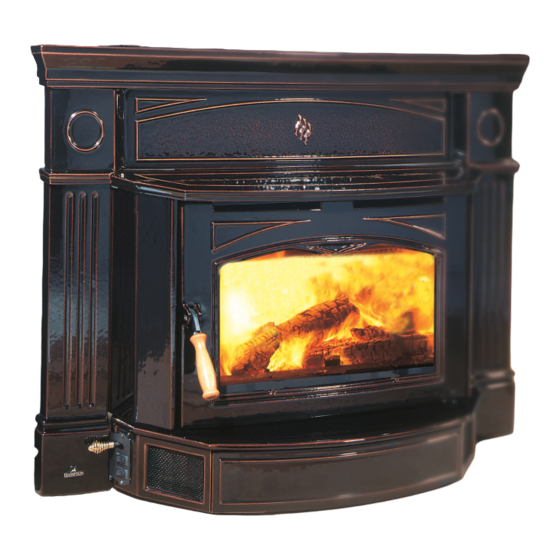
HAMPTON BAY Hamilton HI300 Owners & Installation Manual
Wood cast insert
Hide thumbs
Also See for Hamilton HI300:
- Owners & installation manual (40 pages) ,
- Brochure & specs (16 pages) ,
- Owners & installation manual (36 pages)
Table of Contents
Advertisement
Quick Links
Wood cast insert
owners &
installation Manual
www.hampton-fire.com
MODEL:
HI300
Tested by:
Installer: please complete the details on the back cover
and leave this manual with the homeowner.
Homeowner: please keep these instructions for future reference.
fpi fireplace products international ltd. 6988 Venture st., delta, Bc canada, V4G 1H4
918-240h
10/18/11
Advertisement
Table of Contents

Related Manuals for HAMPTON BAY Hamilton HI300


Summary of Contents for HAMPTON BAY Hamilton HI300
- Page 1 Tested by: Installer: please complete the details on the back cover and leave this manual with the homeowner. Homeowner: please keep these instructions for future reference. fpi fireplace products international ltd. 6988 Venture st., delta, Bc canada, V4G 1H4 918-240h 10/18/11...
- Page 2 Thank-you for purchasing a HaMpton fireplace product. The pride of workmanship that goes into each of our products will give you years of trouble-free enjoyment. Should you have any questions about your product that are not covered in this manual, please contact the HaMpton dealer in your area.
-
Page 3: Table Of Contents
table of contents safetY laBel operatinG instructions Safety Label For HI300..........4 Safety Guidelines ............21 First Fire ..............21 unit diMensions Creosote ..............22 Ash Disposal..............22 Fan Operation .............22 Standard faceplate ............5 Wood Storage ..............22 Oversize faceplate ............6 Maintenance installation Door Gasket ..............23 Before Installing Your Insert...........7 Glass Cleaning ............23 Chimney Specifications ..........7... -
Page 4: Safety Label
safetY label safetY laBel for Hi300 This is a copy of the label that accompanies your Hampton insert. We have printed a copy of the contents here for your review. note: Hampton units are constantly being improved. Check the label on the unit and if there is a difference, the label on the unit is the correct one. -
Page 5: Standard Faceplate
Dimensions WitH standard cast faceplate note: Before assembling your insert, use these dimensions to ensure appropriate clearances will be met (refer to Masonry and fac- tory Built fireplace clearances section). Hampton HI300 Wood Cast Insert... -
Page 6: Oversize Faceplate
Dimensions WitH oVersize note: cast faceplate Before assembling your insert, use these dimensions to ensure appro- priate clearances will be met (refer to Masonry and factory Built fireplace clearances section). Hampton HI300 Wood Cast Insert... -
Page 7: Before Installing Your Insert
installation cHiMneY 7) Circulating air chambers (i.e. in a steel Hampton Inserts are constructed with the high- est quality materials and assembled under strict fireplace liner or metal heat circulator) shall specifications quality control procedures that insure years of not be blocked. trouble free and reliable performance. -
Page 8: Masonry And Factory Built Fireplace Clearances
installation MasonrY and factorY Built fireplace clearances The minimum required clearances to combustible materials when installed into a masonry or factory built fireplace are listed below. note: Clearances are the same with standard or oversize cast faceplate. adjacent mantle** side minimum minimum minimum... -
Page 9: Installing Your Insert
installation WarninG stop! please read carefullY. do not lift or pusH tHe unit froM tHe asHlip, left side cast or riGHt side cast. cast coMponents are VerY fraGile. tHe castinG Will cHip or Break. use extreMe care WHen HandlinG. installinG Your insert Your insert is very heavy and will require two or three people to move it into position. -
Page 10: Installation Into A Masonry Fireplace
installation installation into a installation into a factorY Built fireplace MasonrY fireplace The insert must be installed as per the requirements of your local in- 1) When installed in a factory built fireplace, a full stainless steel rigid spection authority. While a full liner is preferred, three methods of flue or flexible flue liner is mandatory, for both safety and performance connection are acceptable in most areas in the US, however in Canada purposes. -
Page 11: Standard Cast Faceplate Installation
installation CAST FACEPLATE standard cast faceplate INSTALLATION HI300 installation Secure the Left and Right Side Faceplate to the fi rebox by align- FACEPLATE CONTENTS LIST ing the Mounting Holes with the Side Mounting Brackets taking Description care to align vertically while each side rests on the hearth. Secure using 1 bolt per bracket. - Page 12 CAST FACEPLATE INSTALLATION installation HI300 Slowly slide the Mantel Top forward until it stops. Retainer Top Faceplate Slide Mantel Mounting Plates Mount the Top Faceplate by carefully sliding the Mounting Plates on the Left and Right Side Faceplate thru the Retainers in the Top Faceplate.
- Page 13 CAST FACEPLATE INSTALLATION installation HI300 RECOMMENDED MEASUREMENTS Location of Insulation: FOR SETTING SIDE CASTS Place 1 piece of Insulation behind the Mantel Top. Stop! Read Carefully. Cut the second piece of Insulation in half, then install behind both the Left and Right Sides as shown. Enamel &...
-
Page 14: Oversize Cast Faceplate Installation
HI300 installation oVersize cast faceplate installation OVERSIZE CAST FACEPLATE INSTALLATION Stop! Read Carefully. Enamel & Cast components are very fragile. Use extreme care when handling. 2) Secure the Left and Right Side Faceplate to the fi rebox by aligning FACEPLATE CONTENTS LIST the Mounting Holes with the Side Mounting Brackets taking care to Description align vertically while each side rests on the hearth. - Page 15 HI300 installation 5) Slowly slide the Mantel Top forward until it stops. 8) Carefully slide the Mantel Top back into position. Slide Mantel Top Slide Mantel Top back. 6) Place supplied gasket to bottom edge of top faceplate - continue gasket up each side at a 45°...
- Page 16 HI300 installation SIDE CAST ADJUSTMENTS RECOMMENDED MEASUREMENTS FOR SETTING SIDE CASTS If unable to align side faceplate to unit and top Stop! Read Carefully. faceplate further adjustments need to be made, complete one Enamel & Cast components are very fragile. side at a time.
-
Page 17: Fan Installation
installation fan installation installer: Please record unit serial number here before installing blower. Serial No.______________________________ Your fan should only be installed once the unit is in place in order iMportant to prevent any damage to the fan. ensure that the left and right side fan facia do not hit the sides of the faceplate when sliding the fan into 1) Attach the Left and Right Side Fan Facia to the Front Fan position as the casting may chip. -
Page 18: Power Outlet Conversion
installation POWER OUTLET CONVERSION poWer outlet conVersion HI300 1) Remove the Phillips screw, located on the top of the 5) Raising the fan defl ector, pull the wire harness, switch fan housing, which attaches the fan defl ector to the plate, ground wire and thermodisc assembly from main fan body. - Page 19 POWER OUTLET CONVERSION installation HI300 9) Remove the wires one at a time from the existing switch plate, and attach each wire to the new switch plate, each wire in the same position as it was on the old switch plate (see wiring diagram). Discard the old switch plate.
-
Page 20: Firebrick Assembly
installation draft control fireBrick asseMBlY hand side, as far as possible and then bring it back into the hole on the right hand side. Use a pair of vise grips or pliers and tap it Before establishing your first fire, it is important Firebrick is included to extend the life of your into place with a hammer. -
Page 21: Operating Instructions
operatinG instructions installation safetY 14) Do not burn salt drift wood as it will corrode 7) For the first few hours, the insert will give your unit and void the warranty. off an odor from the paint. This is to be Guidelines expected as the high temperature paint 15) Do not operate the unit if the glass is broken... -
Page 22: Creosote
operatinG instructions creosote Wood storaGe fan operation When wood is burned slowly, it produces tar Store wood under cover, such as in a shed, or The fan is to be operated only with the draft and other organic vapors, which form creosote covered with a tarp, plastic, tar paper, sheets control rod pulled out at least 1/2"... -
Page 23: Maintenance
Maintenance door Gasket Glass Handle replaceMent replaceMent If the door gasket requires replacement, 7/8" diameter material must be used. A proper high 1) Open door. temperature gasket adhesive is required. A 1) Remove handle by undoing the hex head bolt gasket repair kit, Part # 846-570 is available using a 7/16"... -
Page 24: Latch Adjustment
Maintenance latcH adjustMent The door latch may require adjustment as the door gasket material compresses after a few fires. Removal of spacers will allow the latch to be moved closer to the door frame, causing a tighter seal. 1) Remove the Latch Assembly from the unit by undoing the outer 2 3) Remove necessary amount of spacers sitting on the Mounting bolts. -
Page 25: Annual Maintenance
Maintenance annual maintenance Completely clean out entire unit Annually Inspect air tubes, baffles and bricks Replace any damaged parts. Adjust door catch / latch If unable to obtain a tight seal on the door - replace door gasket seal. Readjust latch after new gasket installed. Inspect condition and seal of: Glass Gasket Door Gasket... -
Page 26: Parts List
parts list Main asseMBlY part # description part # description 942-661* Mantel Top 942-681* Right Side Cast 936-238 Side Cast Gasket Glass Retainer 15) 300-911* Fan Assembly 936-238 Glass Gasket (sold per ft.) 300-021 Flange Adaptor 20) 300-541* Door Assembly 36) 033-953 Air Tube 3/4"... -
Page 27: Standard Cast Faceplate
parts list standard cast faceplate part # description 300-921 Cast Faceplate - Metallic Black 300-925 Cast Faceplate - Timberline Brown 300-926 Cast Faceplate - Enamel Black 200) * Top Faceplate 201) * Left Side Faceplate 202) * Right Side Faceplate * Not available as a replacement part. -
Page 28: Oversize Cast Faceplate
parts list oVersize cast faceplate part # description 300-971 Oversize Cast Faceplate - Metallic Black 300-975 Cast Faceplate - Timberline Brown 300) * Top Faceplate 301) * Left Side Faceplate 302) * Right Side Faceplate 303) 300-060 Mounting Plate LH 300-061 Mounting Plate RH 304) 300-005... -
Page 29: Brick Panels
parts list Brick panels part # description 180-960 Brick Set - Complete Hampton HI300 Wood Cast Insert... - Page 30 notes Hampton HI300 Wood Cast Insert...
-
Page 31: Warranty
At no time will FPI be liable for any consequential damages which exceed the purchase price of the unit. FPI has no obligation to enhance or modify any unit once manufactured. ie. as products evolve, fi eld modifi cations or upgrades will not be performed. - Page 32 Installer: Please complete the following information dealer name & address: ______________________________________________ ___________________________________________________________________ installer: ___________________________________________________________ phone #: ___________________________________________________________ date installed: ______________________________________________________ serial no.: __________________________________________________________ Hampton is a trademark of FPI Fireplace Products International Ltd. printed in canada © FPI Fireplace Products International Ltd. 2011...