HAMPTON BAY Hamilton H15 Owners & Installation Manual
Direct vent gas fireplace
Hide thumbs
Also See for Hamilton H15:
- Brochure & specs (16 pages) ,
- Owners & installation manual (60 pages) ,
- Owners & installation manual (60 pages)
Table of Contents
Advertisement
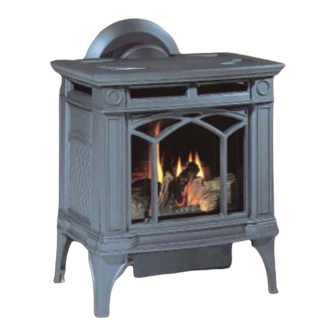
H15 Direct Vent Gas Fireplace
WARNING:
If the information in these instructions are not
followed exactly, a fi re or explosion may result
causing property damage, personal injury or loss
of life.
FOR YOUR SAFETY
Do not store or use gasoline or other fl ammable
vapours and liquids in the vicinity of this or any
other appliance.
Installation and service must be performed by
a qualifi ed installer, service agency or the gas
supplier.
Tested by:
918-516c
FPI FIREPLACE PRODUCTS INTERNATIONAL LTD. 6988 Venture St., Delta, BC Canada, V4G 1H4
MODELS:
H15-NG1 Natural Gas
FOR YOUR SAFETY
What to do if you smell gas:
Do not try to light any appliance
Do not touch any electrical switch:
do not use any phone in your
building.
Immediately call your gas supplier
from a neighbour's phone. Follow
the gas supplier's instructions.
If you cannot reach your gas sup-
plier, call the fi re department.
Installer: Please complete the details on the back cover
and leave this manual with the homeowner.
Homeowner: Please keep these instructions for future reference.
www.hampton-fi re.com
H15-LP1 Propane
This appliance may only be
installed in an aftermarket
permanently located, manu-
factured (USA only) or mobile
home, where not prohibited by
local codes.
This appliance is only for use
with the type of gas indicated
on the rating plate. This ap-
pliance is not convertible for
use with other gases, unless
a certifi ed kit is used.
Owners &
Installation Manual
04/12/11
Advertisement
Table of Contents

Related Manuals for HAMPTON BAY Hamilton H15


Summary of Contents for HAMPTON BAY Hamilton H15
- Page 1 Tested by: Installer: Please complete the details on the back cover and leave this manual with the homeowner. Homeowner: Please keep these instructions for future reference. 04/12/11 918-516c FPI FIREPLACE PRODUCTS INTERNATIONAL LTD. 6988 Venture St., Delta, BC Canada, V4G 1H4...
- Page 2 You are the owner of a state-of-the-art Hampton Gas Stove by FPI FIREPLACE PRODUCTS INTERNATIONAL LTD. The H15-1 is a hand crafted appliance and has been designed to provide you with all the warmth and charm of a wood fi replace at the fl...
-
Page 3: Unit Dimensions
SAFETY LABEL DIMENSIONS UNIT DIMENSIONS Hampton® H15-1 Direct Vent Freestanding Gas Stove Hampton® H15-1 Direct Vent Freestanding Gas Stove... -
Page 4: Table Of Contents
DIMENSIONS DIMENSIONS Conversion from NG to LP ..........31 Log Set Installation ............34 Optional Wall Thermostat ...........36 Unit Dimensions ............3 Optional Remote Control ..........36 Final Check..............36 SAFETY LABEL Wiring Diagrams ............37 Copy of Safety Decal .............5 OPERATING INSTRUCTIONS REQUIREMENTS Operating Instructions ..........39 Lighting Procedure ............39 Shutdown Procedure ...........39 MA Code - CO Detector..........5... -
Page 5: Safety Label
à demeure si les règlements locaux le permettent. Voir la notice de l'utilisateur pour plus de renseignements. Cet appareil ne peut pas être utilisé avec d'autres gaz sauf si une trousse de conversion certifiée est fournie. FPI Fireplace Products International Ltd. This vented gas fireplace heater is not for use with air filters. -
Page 6: Requirements
REQUIREMENTS MA Code - CO Detector (for the State of Massachusetts only) 5.08: Modifications to NFPA-54, Chapter 10 (2) Revise 10.8.3 by adding the following additional requirements: (a) For all side wall horizontally vented gas fueled equipment installed in every dwelling, building or structure used in whole or in part for residential purposes, including those owned or operated by the Commonwealth and where the side wall exhaust vent termination is less than seven (7) feet above finished grade in the area of the venting, including but not limited to decks and porches, the following requirements shall be satisfied:... -
Page 7: Installation
INSTALLATION IMPORTANT MESSAGE This appliance installation must comply with the WARNING: FAILURE TO INSTALL THIS manufacturer's installation instructions and local SAVE THESE APPLIANCE CORRECTLY WILL VOID codes, if any. In the absence of local codes follow the current National Fuel Gas Code, ANSI Z223.1 YOUR WARRANTY AND MAY CAUSE A INSTRUCTIONS and the current National Electrical Code ANSI/NFPA... -
Page 8: General Safety Information
INSTALLATION 1) Provide adequate clearances for servicing, 3) The appliance should be inspected for shipping 7) Install standard and optional features. Refer proper operation and around the air openings damage before use and serviced annually by to the following sections where applicable: into the combustion chamber. -
Page 9: Clearances To Combustibles
INSTALLATION CLEARANCES TO LOCATING YOUR COMBUSTIBLES GAS STOVE When selecting a location for your stove, ensure The clearances listed are MINIMUM distances. that the clearances listed above are met as well Measure the clearance to both the appliance and as ensuring that there is adequate accessibility for the chimney connector. -
Page 10: Optional Fan Installation
INSTALLATION OPTIONAL FAN 4) Remove the nylon hole plug from the control 9) Remove 2 screws from unit. panel. INSTALLATION 5) Install the fan speed controller onto the control panel and secure with nut and washer. Connect Fan Kit Contains: the red and black wires from the wire harness to speed controller. - Page 11 INSTALLATION 12) Slide fan into place and secure with the two 15) Before re-attaching the rear access panel, the valve wires and the fan screws removed in step 9. wires need to be connected. Lug Nut 13) Connect long black & red wires to thermodisc and secure wires. Re-connect the red and grey valve wires removed in step 2.
-
Page 12: Venting Introduction
POSITION 3) Installation other than as instructed by Simpson Note: These fl ue pipes must not be Dura-Vent and FPI Fireplace Products Interna- connected to any other appliance. tional Ltd. To set the Vent restriction as indicated in the Venting Arrangement diagrams in the "Rigid... -
Page 13: Exterior Vent Terminal Locations
INSTALLATION EXTERIOR VENT TERMINAL LOCATIONS Minimum Clearance Requirements Canada Clearance above grade, veranda, porch, deck, or balcony 12"(30cm) 12"(30cm) Clearance to window or door that may be opened 12"(30cm) 9" (23cm) Clearance to permanently closed window Vertical clearance to ventilated soffi t located above the terminal within a horizontal distance of 2 feet (61cm) 22"(56cm) 22"(56cm) from the center line of the terminal (check with the local code) -
Page 14: 4" X 6-5/8" Rigid Pipe
INSTALLATION 4” X 6-5/8” RIGID PIPE CROSS REFERENCE CHART Components from different Manufacturers may not be mixed. Not All Rigid Pipe components are available directly from FPI. Description Selkirk American Metal Security ICC Excel Simpson Metal-Fab™ Direct Temp™ Secure- Vent®... - Page 15 Vinyl Siding Standoff for AstroCap Note: When using Metal-Fab Sure Seal Rigid Piping - please note that the Adaptor (4DDA) must be used in conjunction with FPI Rigid Pipe Adaptor (510-994). Offset Pipe Selection: Use this table to determine offset pipe lengths.
-
Page 16: Rigid Pipe Venting Systems
Intertek WHI listing of components. ® The FPI AstroCap and FPI Riser Vent terminal are certifi ed for installations using FPI venting systems as well as Simpson Dura-Vent Direct Vent, ® American Metal Products Ameri Vent Direct Vent, Security Secure Vent , Selkirk Direct-Temp. - Page 17 INSTALLATION Horizontal Venting with Two (2) 90 Elbows One 90 elbow = Two 45 elbows. Option H + H1 With these options, maxi- 1' Min. 3' Max. mum total pipe length is 30 2' Min. 4' Max. feet with minimum of 6 feet total vertical and maximum 3' Min.
- Page 18 INSTALLATION Vertical Venting with Two (2) 90 Elbows One 90 elbow = Two 45 elbows. Option V V + V1 With these options, max. total pipe length is 30 feet with min. 1' Min. 4' Max. 2' Min. of 6 feet total vertical and max. 2' Min.
-
Page 19: Venting Arrangements
45 elbow off the unit. Restrictor position "A". 12" max. w/AstroCap or Simpson Duravent Horizontal Square Termination Cap. 24" max. w/FPI Riser or Snorkel Termination Cap. Hampton® H15-1 Direct Vent Freestanding Gas Stove... -
Page 20: Vertical Termination With Co-Linear Flex System
INSTALLATION VERTICAL TERMINATION WITH CO-LINEAR FLEX SYSTEM Masonry chimneys may take various contours which the fl exible liner will accommodate. However, keep THE APPLIANCE MUST NOT BE the fl exible liner as straight as possible, avoid unnecessary bending. CONNECTED TO A CHIMNEY FLUE SERVING A SEPARATE SOLID FUEL The Air Intake pipe must be attached to the inlet air collar of the termination cap. -
Page 21: Dv Stove Horizontal Vent Kit
INSTALLATION DV STOVE HORIZONTAL VENT KIT DV 2 ft. Stove Vent Kit (Part # 946-116) and DV 4 ft. Stove Vent Kit (946-216) includes all the parts needed to install the H15-1 Direct Vent unit with up & out horizontal and vertical vent dimensions. For installations that require longer vertical and/or horizontal vents use the Dura-Vent system as shown in the "Dura-Vent Termina- tion Kit"... - Page 22 INSTALLATION 10) Slide the decorative Thimble Cover over the pipe sections and secure with 4 screws (#8 x 1-1/2" drill point, black) to the wall. 11) Slide the 90 elbow (crimp end up), the 45 elbow and the 4 ft. pipe section (crimp end up) over the 4"...
-
Page 23: Residential And Manufactured Homes
INSTALLATION RESIDENTIAL AND MANUFACTURED HOMES / MOBILE HOMES MINIMUM HORIZONTAL TERMINATION INSTALLATIONS Planning Your Venting Installation You will require the following components with your new Hampton ® Direct Vent Freestanding Gas Stove. Please review your product to make sure you have everything you need. In the event that you are See the "Exterior Vent Terminal Locations"... -
Page 24: Dura-Vent Termination Kit
Terminal 1 Horiz. Sq. Term. Cap Part# 640-530/P The FPI AstroCap is certifi ed for installations using FPI venting systems as well as Simpson Dura-Vent® and Direct Vent. The FPI AstroCap is a proprietary trademark of FPI Fireplace Prod- ucts International Ltd. -
Page 25: Horizontal Terminations
INSTALLATION Please review your product to make sure you have everything you need. In the event that you are Note: missing any part, contact your dealer. Note: These are the minimum pieces required. Other parts may be required for your particular installation. -
Page 26: Vertical Terminations
INSTALLATION c) Before connecting the vent pipe to the vent termination, slide the black decorative wall thimble cover over the vent pipe, then slide the Wall Penetration Heat Shield (Part # 946-202) over the vent pipe. Dia. 3. d) Slide the appliance and vent assembly towards the wall carefully inserting the vent pipe into the riser vent terminal assembly. - Page 27 INSTALLATION 3) To install the Round Support Box/Wall Thim- 7) Ensure vent is vertical and secure the base of the fl ashing to the roof with roofi ng rails, slide storm collar over the pipe section and seal with a mastic. 8) Install the vertical termination cap by twist locking it.
-
Page 28: Converting Class-A Metal Chimney Or Masonry Chimney To Direct Vent System
INSTALLATION 4) Pass the fl ex pipe down through the center of CONVERTING CLASS-A Approved for US Installations Only the chimney system, and center the adaptor The use of an existing chimney as an air intake METAL CHIMNEY OR on the top of the chimney pipe. Drill four 1/8" is not covered under the ANS Z21.88a-2007/ diameter holes through the adaptor and into CSA 2.33a-2007 test methods and the re-... -
Page 29: Cathedral Ceilings
INSTALLATION CATHEDRAL CEILINGS 4) Assemble the desired lengths of Black Pipe and Elbows necessary to reach from the appliance IMPORTANT: ALWAYS CHECK FOR adapter up through the support box and fl ashing GAS LEAKS WITH A SOAP AND WA- Round Support (RDS) & to proper height as per Dia. -
Page 30: Aeration Adjustment
2) Loosen the "IN" and/or "OUT" pressure tap(s), Note: Aeration Adjustment should only be turning counterclockwise with a 1/8" wide fl at performed by an authorized FPI Installer screwdriver. at the time of installation or service. 3) Attach manometer to "IN" and/or "OUT" pressure tap(s) using a 5/16"... -
Page 31: Conversion From Ng To Lp
INSTALLATION CONVERSION KIT# 381-969 FROM NG TO LP THIS CONVERSION MUST BE DONE BY A QUALIFIED GAS FITTER IF IN DOUBT DO NOT DO THIS CONVERSION !! Check that the screw is clean and if Remove burner by removing the 2 screws necessary remove dirt. -
Page 32: Installation Of The Dc Sparker
INSTALLATION 11) Reassemble the black protection cap 16) Reverse steps 3) to 2). 22) Attach the DC sparker generator (Fig. 6). connector to the valve with a screw. 17) Attach the label "This unit has been converted to LPG" near or on top of the serial # decal. - Page 33 INSTALLATION 25) Attach the Piezo ignition wire to the DC 29) Attach the DC sparker generator wires to 32) Tie up the loose wire with the wire clip. Sparker. the DC sparker. Piezo Ignitor 30) Install the supplied battery into the DC Sparker Box by opening the battery compartment.
-
Page 34: Log Set Installation
INSTALLATION LOG SET INSTALLATION Read the instructions below carefully and refer to the 5) Carefully remove the logs from the unit and diagrams. If the logs are broken do not use the unit unwrap them. The logs are fragile, handle with until they are replaced. - Page 35 INSTALLATION 8) Take the embers and place on the burner in the 9) Place the center cross log on the top of the rear log space between the 2 front logs, ensure not to cover and position as shown below. any burner ports.
-
Page 36: Optional Wall Thermostat
INSTALLATION OPTIONAL FINAL CHECK OPTIONAL REMOTE WALL THERMOSTAT CONTROL Before leaving this unit with the customer, the installer must ensure that the appliance is fi ring ® Use the Hampton Remote Control Kit approved correctly. This includes: A wall thermostat may be installed if desired. for this unit. -
Page 37: Wiring Diagrams
INSTALLATION WIRING DIAGRAMS Caution: Ensure that the wires do If any of the original wires as supplied with the appliance must be replaced, it must be replaced CAUTION: Label all wires prior not touch any hot surfaces and are with CSA type SEW (200 C) or its equivalent. - Page 38 INSTALLATION PROPANE Units and Units Equipped with DC Spark Boxes* *For installation of the DC Spark Box refer to the LP Conversion instructions in this manual. Hampton® H15-1 Direct Vent Freestanding Gas Stove...
-
Page 39: Operating Instructions
OPERATING INSTRUCTIONS INSTALLATION the paint and the burning off of any oils remaining OPERATING from manufacturing. Smoke detectors in the house INSTRUCTIONS may go off at this time. Open a few windows to ventilate the room for a couple of hours. The glass may require cleaning. -
Page 40: Copy Of The Lighting Plate Instructions
OPERATING INSTRUCTIONS COPY OF THE LIGHTING PLATE INSTRUCTIONS FOR YOUR SAFETY READ BEFORE LIGHTING NFPA 54, or Natural Gas and Propane Installation Codes, CSA B149.1. (Australia: A S5601-2004, New Zealand: NZS 5261) WARNING: If you do not follow these instructions exactly, a fire or explosion may result causing property damage, or additional information consult a qualified installer, service agency or gas supplier. -
Page 41: Normal Operating Sounds Of Gas Appliances
MAINTENANCE NORMAL OPERATING 2) Clean glass (never when unit is hot), appliance, CLOTHING OR OTHER FLAMMABLE and door with a damp cloth. Never use an MATERIAL SHOULD NOT BE PLACED SOUNDS OF GAS abrasive cleaner. ON OR NEAR THE APPLIANCE. APPLIANCES 3) The heater is fi... -
Page 42: Fan Maintenance
MAINTENANCE GENERAL VENT GLASS REPLACEMENT FAN MAINTENANCE MAINTENANCE Your stove is supplied with high temperature, 5 If your fan requires maintenance or replacement, mm Neoceram ceramic glass that will withstand access to the fan is through the rear access panel Conduct an inspection of the venting system the highest heat that your unit will produce. -
Page 43: Removing Valve
MAINTENANCE 12) To remove the valve, remove the 4 screws (2 REMOVING VALVE 9) Remove burner by removing the 2 screws per bracket) that hold the valve to the valve on each side, slide the burner to the left and bracket assembly. -
Page 44: Parts List
PARTS LIST MAIN ASSEMBLY Part # Description Part # Description Part # Description 380-012 Rear Panel 942-601** Casting - Top 380-011 Restrictor 910-330 Fan Speed Control (120V) 942-621** Casting - Side & Leg 948-255 Latch Ojop W/J-Hook 904-569 Knob - Fan Speed Control 942-611** Casting - Front 940-338/P Replacement Glass... -
Page 45: Burner & Log Assembly
PARTS LIST BURNER & LOG ASSEMBLY Part # Description 380-574/P Valve/Pilot Assembly - S.I.T. - NG 910-478 Valve S.I.T. - NG/LPG 904-434 #47 Orifi ce - NG 910-190 Piezo Ignitor & Nut 908-672 Control Panel Decal 490-061 Switch Plate 936-170 Orifi... - Page 46 NOTES Hampton® H15-1 Direct Vent Freestanding Gas Stove...
-
Page 47: Warranty
At no time will FPI be liable for any consequential damages which exceed the purchase price of the unit. FPI has no obligation to enhance or modify any unit once manufac- tured. ie. as products evolve, fi eld modifi cations or upgrades will not be performed. - Page 48 Dealer Name & Address: ______________________________________________ ___________________________________________________________________ Installer: ___________________________________________________________ Phone #: ___________________________________________________________ Date Installed: ______________________________________________________ Serial No.: __________________________________________________________ Hampton is a trademark of FPI Fireplace Products International Ltd. Printed in Canada © Copyright 2011, FPI Fireplace Products International Ltd. All rights reserved.