Table of Contents
Advertisement
Quick Links
Advertisement
Table of Contents

Related Manuals for Shop fox SHOP FOX W1811


Summary of Contents for Shop fox SHOP FOX W1811
-
Page 3: Table Of Contents
Woodstock Technical Support ....2 Schedule ......... 52 Overview of Machine ......2 Cleaning ......... 52 Controls and Features ......3 Table & Base ........52 Machine Specifications ......4 Lubrication ........53 Sliding Table Saw Capacities ....6 General .......... 54 Standard Machinery Safety ..... - Page 4 Woodstock International, Inc. is committed to customer satisfaction. Our intent with this manual is to include the basic information for safety, setup, operation, maintenance, and service of this product.
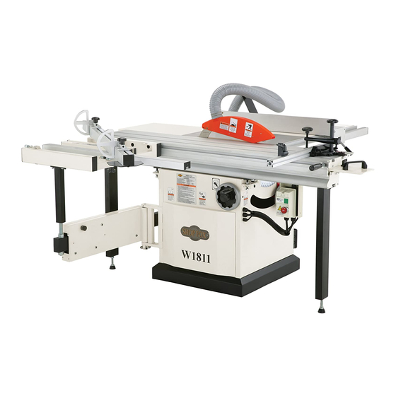
- Page 5 Fence Positions Main view of machine features and controls. : Provides a wide, stable : Fence face can be positioned platform for supporting full-size panels for standard cutting operations, or in the during crosscutting operations. Also fea- lower position for blade guard clearance tures an angle scale for cutting miters with during narrow ripping operations.
- Page 6 Phone #: (360) 734-3482 • Online Tech Support: tech-support@shopfox.biz • Web: www.shopfox.biz Type ..................TEFC Capacitor Start Induction Horsepower ......................... 5 HP Voltage ........................220V Phase ........................Single Amps .......................... 22A Speed ........................3450 RPM Cycle ........................60 Hz Number Of Speeds ......................1 Power Transfer ....................
- Page 7 Number of Crates ......................2 Type ......................Cardboard/Wood Content ........................Machine Crate 1 Length/Width/Height ................46" x 42" x 44" Crate 1 Weight ......................528 lbs. Crate 2 Length/Width/Height ................67" x 18 ⁄ " x 10" Crate 2 Weight ......................117 lbs. Switch Type ..............
- Page 8 Phone #: (360) 734-3482 • Online Tech Support: tech-support@shopfox.biz • Web: www.shopfox.biz Ripping Width Cross Cut Miter Cut 90º Miter Cut 45º (push cut) (push cut) Cross Cut (fence not extended) Miter Cut 45º Miter Cut 45º Miter Cut 45º (push cut, fence not extended) (fence not extended)
- Page 11 Always use the blade guard and riving knife on all ''through-sawing'' opera- tions. Be familiar with kickback. Kickback happens when the workpiece is thrown towards the operator at a high rate of speed. Make sure the workpiece is placed in a stable position on the table and is either supported by the rip fence or the crosscut table during cutting operations.
- Page 12 • Only cut workpieces with at least one smooth and straight edge. DO NOT cut warped, cupped or twisted wood. • Never attempt freehand cuts. If the workpiece is not fed parallel with the blade, kickback will likely occur. Always use the rip fence or miter gauge to support the workpiece.
- Page 13 The following is a list of common definitions, terms and phrases used throughout this manual as they relate to this table saw and woodworking in general. Become familiar with these terms for assembling, adjusting or operating this machine. Being an equal distance apart at every A metal shaft extending from the drive point along two given lines or planes (i.e.
-
Page 14: Extension Cords
The Model W1811 is wired for 220V single-phase operation. We recommend connecting this machine to a dedicated circuit with a verified ground, using the circuit size given below. Never replace a circuit breaker with one of higher amperage without consulting a qualified electrician to ensure compliance with wiring codes. -
Page 15: Dust Collection
The following items are needed to complete the setup process, but are not included with your machine: • Safety Glasses (for each person) ......1 • Forklift ............1 • Lifting Straps (2000 lb capacity) ......2 • An Assistant ..........1 • Straightedge 4' (or longer) .......1 •... - Page 16 The following is a description of the main components shipped with the Model W1811. If you can't find an item on this list, check the mounting location on the machine or examine the packaging materials carefully. Occasionally we pre-install certain components for safer shipping.
- Page 17 Miter Clamp ..........1 Miter Flip Stop ..........1 Miter Handle w/Flat Washer 8mm ......1 Miter Gauge Fence ........1 Miter Gauge Body ..........1 Miter Guide Bar ..........1 Sliding Table ..........1 Sliding Table Support Legs .......2 Feet M12-1.75 x 75 w/Nuts ......2 Crosscut Brace Knobs M8-1.25 x 50 .....2 Miter gauge items.
- Page 18 This machine distributes a The table and other unpainted parts of your heavy load in a small footprint. Make machine are coated with a waxy grease that sure the floor will support the machine, protects them from corrosion during shipment. workpieces, and the operator.
- Page 19 Feed the lifting straps around the lifting bolts on the back of the table and the sliding table saw mounts on the front of the cabinet (see ). Attach the ends of the lifting straps to the forklift forks. Lift the table saw cabinet and move it to your pre- determined location.
- Page 20 Before shipping, the sliding table was installed on the machine and calibrated to the main table and blade. As such, be careful not to move any pre-installed nuts when installing the sliding table. The sliding table and extension tables are heavy, so use a forklift or four strong helpers to lift the sliding table during installation.
- Page 21 Mount the rip fence scale to the large extension table and cast iron table ( ) using three M6-1 hex nuts, 6mm lock washers, 6mm flat wash- ers, two M6-1 x 16 hex bolts, and one M6-1 x 25 hex bolt.
- Page 22 Slide the rip fence base on the rail, and check the Spacing spacing between the rip fence base and scale bar (see ). There should be a minimum of ⁄ " of space between the scale bar and the fence base. Adjust the mounting position of the rip fence rail to create this space evenly along the length of the scale bar, then tighten the rail mounting nuts.
- Page 23 Place a 12mm flat washer on the crosscut table lock lever, then insert it through the crosscut Lock Lever fence and thread the M12-1.75 T-nut onto the end approximately two turns. Align the T-nuts on the crosscut table with the T-Slot T-slot in the face of the sliding table, then slide the crosscut table into position on the sliding table...
- Page 24 Slide the pivot stud assembly and the M8-1.25 x 60 Pivot Stud T-bolt into the crosscut fence T-slot, as shown in Assembly Align the T-bolt and pivot stud with the crosscut table insertion points ( ), and install the fence on the table. Thread the M8-1.25 knob with an 8mm flat washer onto the bottom of the T-bolt from the underside of the table.
- Page 25 Remove the shipping brace from the sliding table Shipping ), then install the sliding table end cover Brace over the fixed part of the sliding table end, as shown , using the pre-mounted hardware. Sliding table shipping brace. Sliding table end cover installed.
- Page 26 Thread the feet all the way into the bottom of the support legs. DO NOT remove the hex nuts pre- installed on the bottom of the feet, since they will be used after the legs are installed. Thread two M10-1.5 x 30 cap screws and 10mm lock washers through each support leg and part way into the T-slot plates for the legs, slide the T-slot plates into the both ends of the sliding table base, and...
- Page 27 Install the riving knife as shown in , but do not tighten the mounting bolt yet. Installing riving knife. Adjust the riving knife approximately ⁄ " away from the main blade, using a ⁄ " or 3mm hex wrench as a guide ( ), and make sure the top of the riv- ing knife is positioned below the blade's highest point...
- Page 28 Install the blade guard on the riving knife, as shown , with the M8-1.25 x 40 button head cap screw shipped in the blade guard. Blade guard installed. Assemble the miter gauge and push handle, as shown Miter Gauge Push Handle Push handle and miter gauge installed.
- Page 29 D3996 Y-Fitting W1038 4" Quick Disconnect Secure a 4" dust hose to the dust port located under the saw table ( Figure . 4" dust port connected. Attach a 2½" dust hose to the blade guard dust port, as shown in Figure .
-
Page 30: Power Connection
Before connecting the saw to power, read through section on to verify that your setup follows the safety and circuit requirements for this machine. Open the power connection box shown in Power Connection Box Power connection box. Connect the power wires to the terminals shown in , tighten the strain relief so the wires can't be pulled from the terminals, then close the power connection box. -
Page 31: Blade Guard
Put on safety glasses, make sure any bystanders are out of the way, and that all tools have been removed from the saw. Push in, then rotate both STOP buttons clockwise until they pop out. This resets the switch so the machine can be started. -
Page 32: Riving Knife
This machine will perform many types of operations that are beyond the scope of this manual. Many of these operations can be dangerous or deadly if performed incorrectly. The instructions in this section are written with the understanding that the operator has the necessary knowledge and skills to operate this machine. - Page 33 Some workpieces are not safe to cut or may require modification before they can be cut. • Nails, staples, dirt, rocks and other foreign objects are often embedded in wood. While cutting, these objects can become dislodged and hit the operator, they can cause kickback, and they can break or chip the blade, which might then fly apart.
- Page 34 A non-through cut is a sawing operation where the blade does not protrude above the top face of the wood stock, as shown in Figure Examples of non-through cuts include dadoes and rabbets. Non-through cuts have a higher risk of injury from kickback because the splitter and blade guard must be removed.
- Page 35 This saw performs best with high-quality sharp blades. Whenever the blades become dull, replace or sharpen them. To change the main blade, do these steps: DISCONNECT SAW FROM POWER! Hole for Arbor Lock Tool Move the blade tilt to 0° (blade 90° to table) and raise the main blade as far as it will go.
- Page 36 The "blade guard" is mounted to the riving knife and is designed to lift as the workpiece is pushed into the blade and remain in contact with the workpiece throughout the entire cut. The guard reduces injury risk by providing a barrier around the blade that prevents accidental contact and contains flying wood chips.
- Page 37 The riving knife ( ) is a metal plate that prevents the newly cut workpiece from pinching the backside of the blade and causing kickback. When properly mounted, the riving knife is positioned below the blade's highest point of rotation, as shown in The height difference between the riving knife and the blade allows the workpiece to pass over the blade during Illustration of a typical riving...
- Page 38 The riving knife must be adjusted to 3mm away from the main saw blade. DISCONNECT SAW FROM POWER! Move the blade tilt to 0˚ (blade 90˚ to table), and raise the main blade as far as it will go. Move the sliding table all the way forward to expose the internal blade guard that covers the blades and riving knife.
- Page 39 Arbor Lock Tool The scoring blade included with the sliding table saw has wedge shaped teeth. The kerf thickness is adjusted by changing the height of the scoring blade. To change the scoring blade, do these steps: DISCONNECT SAW FROM POWER! Move the blade tilt to 0˚...
- Page 40 This saw can only accept a dado blade with ⁄ " arbor hole and a maximum diameter of 8". The maximum width of dado blade that can be installed is ⁄ ". Attempting to install a dado blade that is sized larger than these maximum sizes is dangerous and should be avoided.
- Page 41 Use the ⁄ " drill bit to drill holes completely through the new table insert. Cutaway View Install the ⁄ " drill bit and use the included table of Drilled Hole insert as a guide to set the depth stop on your drill press to countersink the holes.
-
Page 42: Rip Cutting
This saw has the capability of rip cutting large panels ). The sliding table removes the burden of sliding a large and heavy panel over a stationary table surface. This saw also has the capability of rip cutting smaller boards, using the machine as a traditional table saw ). - Page 43 Table Lock Slide the crosscut table out of the way. Lock the sliding table into a stationary position (see Sliding table lock. Place the rip fence in the vertical position for larger workpieces, or in the horizontal position for angled cuts and for small workpieces (see Vertical Horizontal...
-
Page 44: Crosscutting
Forward Mounted This saw can crosscut full size panels with the crosscut Crosscut Fence fence in the forward or rear position, although it is easier to load full size panels with the crosscut fence mounted in the forward position (see Figure . - Page 45 Rear Mounting Install the crosscut fence in the forward mounting Location location shown in and lock it in place. Check to make sure the fence is at 90˚. If necessary, adjust it as described in Set either flip stop to the desired width-of-cut. Extend the crosscut fence slide if the workpiece is Forward Mounting more than 74".
-
Page 46: Miter Cutting
The crosscut fence allows miter cuts from 0˚ through 135˚. The table mounted miter scale has a resolution of 1˚. Slide the crosscut table to the front edge of the slid- ing table and lock it in place. Place the crosscut fence center stud in the left or right stud hole of the crosscut table. - Page 47 Commonly used in furniture joinery, a dado is a straight channel cut in the face of the workpiece. Dadoes can be cut using either a dedicated dado blade or a standard saw Dado operations require proper pro- blade. Refer to to install a dado blade on this cedures to avoid serious injury.
- Page 48 Turn the saw ON and keep one finger ready to push the STOP button. The blade should run smooth with no vibrations. The danger of kickback increases relative to the depth and width of a When the blade has reached full speed, perform a cut.
-
Page 49: Rabbet Cutting
Commonly used in furniture joinery, a rabbet is an L-shaped groove cut in the edge of the workpiece. Rabbets can be cut with either a dado blade or a standard saw blade. Rabbet cutting on the edge of the workpiece requires a sacrificial fence attachment (Figure ). - Page 50 When making rabbet cuts with a standard blade, use a ripping-type blade to reduce motor overloading and blade The danger of kickback increases wear. Also, you will need to remove the blade guard/dust relative to the depth and width of a hood, but leave the riving knife installed, making sure cut.
- Page 51 Resawing is the process of cutting a thick piece of stock into one or more thinner pieces. Serious injury can be caused by kickback. Kickback is a high-speed expulsion of stock from the table saw toward an opera- tor. The operator or bystanders may Resawing on the table saw increases the risk of binding be struck by flying stock, or the oper- the blade and causing kickback.
- Page 52 Pre-drill and countersink 8 pilot holes approximately ⁄ " from the bottom of the 4 ⁄ " tall board. Glue the end of the 3" board, then clamp the boards at a 90° angle with the larger board in the vertical position as shown in Secure the joint with wood screws through the pilot holes made in...
-
Page 53: Shop-Made Safety Accessories
Raise the blade approximately an inch, or close to half the height of the workpiece ( ), which- ever is less. The danger of kickback increases relative to the depth and width of a Plug in the table saw, turn it , and use a push cut. -
Page 54: Schedule
For optimum performance from your machine, follow this maintenance schedule and refer to any specific instructions given in this section. • Loose mounting bolts. • Worn or damaged saw blades. • Worn or damaged switches or wires. • Any other unsafe condition. •... - Page 55 Use multi-purpose grease on the leadscrews ( ) every 6-12 months, at the same time you lubricate the trunnions. Wipe The bearings are sealed and pre-lubri- the leadscrews clean with a dry rag and brush a cated and require no lubrication. light coat of new grease on them with a clean, dry brush.
- Page 56 If you require additional machine service not included in this section, please contact Woodstock International Technical Support at (360) 734-3482 or send e-mail to: DISCONNECT SAW FROM POWER! Tilt the blade to 45˚...
- Page 57 Scoring Belt DISCONNECT SAW FROM POWER! Tilt the blade to 45˚ and lower it as far as it will go. Remove the motor cabinet door. Pull the tensioner away from the scoring belt ( Scoring Belt ) to relieve belt tension and remove the scoring Tensionser belt from the pulleys.
- Page 58 DISCONNECT SAW FROM POWER! Adjust the blade angle until it hits the 45° positive stop and check the blade angle with a 45° square. — If the blade is not 45° to the table, loosen the two 45° Tilt set screws that secure the 45˚ tilt stop nut shown Stop Nut (This nut can also be accessed from the front of the saw by moving the sliding table all...
-
Page 59: Sliding Table Parallelism
Measure the difference between the two positions (use the feeler gauge if using the adjustable square). Parallel Make note of the difference between the two mea- Adjustment Screw surements. — If the gap is the same on both sides or the differ- ence is 0.004"... - Page 60 Squaring the crosscut fence to the blade ensures that cuts made with the crosscut fence will be square. This procedure can be done by using a piece of scrap plywood as a test piece and making five test cuts, then adjusting the fence as necessary.
-
Page 61: Wiring Diagram
These pages are current at the time of printing. However, in the spirit of improvement, we may make changes to the electrical systems of future machines. Study this diagram carefully. If you notice differ- ences between your machine and these wiring diagrams, call Woodstock International Technical Support at (360) 734-3482. - Page 62 Read Page 59 Before Wiring 220 VAC -60-...
- Page 63 Magnetic switch. Read Page 59 Before Wiring Motor junction box. Power connection junction box. -61-...
- Page 64 This section covers the most common problems and corrections with this type of machine. Machine does not start or a 1. Emergency stop push-button is 1. Rotate clockwise slightly until it pops out/replace breaker trips. engaged/faulty. 2. Power supply switched OFF or is at 2.
- Page 65 Machine has vibration or 1. Motor or component is loose. 1. Inspect/replace stripped or damaged bolts/nuts, noisy operation. and re-tighten with thread locking fluid. 2. Blade is at fault. 2. Replace warped, bent, or twisted blade; resharpen dull blade. 3. Belt(s) worn or loose. 3.
- Page 66 PART # DESCRIPTION PART # DESCRIPTION X18110001 TABLE SAW BLADE GUARD LABEL D3376 SHOP FOX NAMEPLATE X18110002 KICKBACK HAZARD LABEL X18110011 MODEL # LABEL (W1811) X18110003 QUALIFIED PERSONNEL LABEL X18110012 MACHINE ID LABEL (W1811) X18110004 BLADE GUARD DANGER LABEL XLABEL-04 ELECTRICITY LABEL X18110005 DISCONNECT POWER LABEL...
-
Page 67: Cabinet
PART # DESCRIPTION PART # DESCRIPTION X18110101 CABINET XPWF10M FENDER WASHER 10MM X18110102 COVER PLATE XPLW06M LOCK WASHER 10MM X18110103 EMERGENCY STOP BUTTON X18110128 FRONT PANEL XPHTEK19M TAP SCREW M5 X 16 XPSS74M SET SCREW M8-1.25 X 35 XPLW06M LOCK WASHER 10MM XPN03M HEX NUT M8-1.25 XPN02M... -
Page 68: Trunnion
PART # DESCRIPTION PART # DESCRIPTION X18110201 CHANNEL BASE XPLW01M LOCK WASHER 5MM X18110202 TRUNNION BRACKET X18110213 BLADE GUARD PLATE XPSB04M CAP SCREW M6-1 X 10 X18110214 HINGE XPLW03M LOCK WASHER 6MM XPS09M PHLP HD SCR M5-.8 X 10 XPSB11M CAP SCREW M8-1.25 X 16 X18110217 MAGNET ASSEMBLY... - Page 69 -67-...
-
Page 70: Main Motor
REF PART # DESCRIPTION REF PART # DESCRIPTION X18110301 BLADE GUARD XPSB14M CAP SCREW M8-1.25 X 20 XPWF08M FENDER WASHER 8MM XPLW04M LOCK WASHER 8MM XPSBS07M BUTTON HD CAP SCR M8-1.25 X 40 XPWF08M FENDER WASHER 8MM X18110304 RIVING KNIFE MOUNTING BLOCK X18110334 ROTATE PLATE XPK34M... -
Page 71: Tables
Sliding Table -69-... -
Page 72: Sliding Table Parts List
Sliding Table Parts List PART # DESCRIPTION PART # DESCRIPTION X18110401 SLIDING TABLE SET 688x316 X18110429 SWITCH MP-18 5HP 220V 1PH X18110402 S. TABLE T-STUD M12-1.75 X 35 429-1 X18110429-1 SWITCH BOX XPW06M FLAT WASHER 12MM 429-2 X18110429-2 CONTACTOR SDE MA-18 220V XPLW05M LOCK WASHER 12MM 429-3 X18110429-3 RELAY SDE RA-30 22-34 25A... -
Page 73: Rip Fence
PART # DESCRIPTION PART # DESCRIPTION X18110501 LARGE EXTENSION TABLE XPHTEK15M TAP SCREW M4 X 10 X18110502 CAST IRON TABLE X18110521 RAIL END PLATE X18110503 TABLE INSERT X18110522 SMALL EXTENSION TABLE XPSB15M CAP SCREW M5-.8 X 20 XPW04M FLAT WASHER 10MM X18110505 RIP FENCE SCALE XPLW06M... - Page 74 PART # DESCRIPTION PART # DESCRIPTION X18110601 RIP FENCE XPHTEK4M TAP SCREW M4 X 8 X18110602 CLAMP PLATE X18110613 LOCK PLATE HANDLE M8-1.25 X18110603 STEEL PIN 6MM XPW01M FLAT WASHER 8MM X18110604 X18110615 RIP FENCE FRONT BASE X18110605 HDPE STRIP X18110616 RIP FENCE REAR BASE XPFS07M...
-
Page 75: Handwheels
PART # DESCRIPTION PART # DESCRIPTION X18110701 LOCK KNOB M10-1.5 X18110722 BEARING SELF LUBRICATING X18110702 HANDWHEEL HANDLE XPW03M FLAT WASHER 6MM X18110703 HANDWHEEL XPR03M EXT RETAINING RING 12MM XPK34M KEY 5 X 5 X 20 X18110725 LOCATE BLOCK X18110705 ANGLE SEAT X18110726 LOCATE SHAFT XPR20M... - Page 76 PART # DESCRIPTION PART # DESCRIPTION X18110801 ARBOR FLANGE X18110812 ADJUST SCREW M8-1.25 X 100 X18110802 SCORING SAW BLADE CSA 22MM X18110813 PLATE XPSB14M CAP SCREW M8-1.25 X 20 XPLW04M LOCK WASHER 8MM X18110804 SHAFT CSA 22MM XPSB31M CAP SCREW M8-1.25 X 25 X18110805 SHAFT X18110816...
-
Page 77: Crosscut Table
PART # DESCRIPTION PART # DESCRIPTION X18110901 CROSSCUT TABLE XPW03M FLAT WASHER 6MM X18110902 PLUG 38 X 38 X18110915 PLUG 80 X 40 X18110903 PLUG 40 X 20 X18110916 PLUG X18110904 T-NUT M12-1.75 X18110917 PIN 3 X 14 X18110905 T-SLOT BAR X18110918 CC BRACE KNOB M8-1.25 X 50 X18110906... -
Page 78: Swing Arm
PART # DESCRIPTION PART # DESCRIPTION 1001 X18111001 CROSSCUT TABLE SUPPORT LEG 1018 X18111018 RING 1002 XPLW03M LOCK WASHER 6MM 1019 X18111019 ADJUST SHAFT 1003 XPSB01M CAP SCREW M6-1 X 16 1020 X18111020 HINGE SHAFT 1004 X18111004 ROTARY SHAFT 1021 XP6202 BALL BEARING 6202ZZ 1005... -
Page 79: Miter Gauge
PART # DESCRIPTION PART # DESCRIPTION 1101 X18111101 MITER GAUGE FENCE 1115 XPSN02M SQUARE NUT M6-1 1102 X18111102 MITER GAUGE BODY 1116 XPW04M FLAT WASHER 10MM 1103 X18111103 LARGE WASHER 1117 XPLN05M LOCK NUT M10-1.5 1104 X18111104 SLIDING MITER CLAMP SHAFT 1118 XPSB38M CAP SCREW M5-.8 X 25... -
Page 80: Crosscut Fence
REF PART # DESCRIPTION REF PART # DESCRIPTION 1201 X18111201 T-NUT M8-1.25 1214 X18111214 LOCATE PLATE 1202 X18111202 STOP BRACKET 1215 X18111215 CC FENCE LOCK KNOB M8-1.25 X 25 1203 X18111203 KNOB M8-1.25 X 40 1216 X18111216 SQUARE FENCE 1204 X18111204 SPECIAL SCREW 1217 X18111217 PIVOT STUD 1205 X18111205 FLIP STOP 1218 X18111218 FIBER WASHER 10MM... - Page 81 Name ___________________________________________________________________________________ Street __________________________________________________________________________________ City _________________________ State ___________________________Zip ________________________ Phone # ______________________ Email___________________________Invoice # ___________________ Model #_________Serial #______________Dealer Name__________________Purchase Date___________ How did you learn about us? _____ Advertisement _____ Friend ____ Local Store _____ Mail Order Catalog _____ Website ____ Other: How long have you been a woodworker/metalworker? _____ 0-2 Years _____ 2-8 Years...
- Page 82 FOLD ALONG DOTTED LINE Place Stamp Here FOLD ALONG DOTTED LINE TAPE ALONG EDGES--PLEASE DO NOT STAPLE...