Table of Contents
Advertisement
Quick Links
Advertisement
Table of Contents
Troubleshooting

Related Manuals for Fujitsu Siemens Computers CELSIUS M


Summary of Contents for Fujitsu Siemens Computers CELSIUS M
- Page 1 Workstation English Operating Manual CELSIUS M / V / R...
- Page 2 Are there ..any technical problems or other questions you would like to discuss? Please contact: ● our Hotline/Help Desk (see the enclosed Help Desk list or go to http://www.fujitsu- siemens.com/support/helpdesk.html) ● Your sales partner ● Your sales office Further information can be found in the "Safety"...
- Page 4 This manual was produced by Xerox Global Services. Published by Fujitsu Siemens Computers GmbH AG 11/07 Edition 6 Order No.: A26361-K990-Z120-1-7619...
-
Page 5: Operating Manual
Introduction Important notes CELSIUS M / V / R Preparing for use Operation Troubleshooting and tips Operating Manual System expansions Technical data Index Edition: November 2007... - Page 6 CELSIUS is a registered trademark of Fujitsu Siemens Computers GmbH. Microsoft, MS, MS-DOS, Windows, Windows NT, Windows 2000, Windows Vista and Windows XP are registered trademarks of Microsoft Corporation. VESA and DPMS are trademarks of Video Electronics Standards Association. PS/2 is a registered trademark of International Business Machines, Inc.
-
Page 7: Table Of Contents
Contents Your CELSIUS............................. 1 Notational conventions ......................... 2 Important notes ..........................3 Safety notes............................3 Transporting the device ........................3 Cleaning the device ..........................3 Energy saving, disposal and recycling ....................4 CE mark..............................4 FCC Class B Compliance Statement ....................5 Preparing for use.......................... - Page 8 Contents Hard disk contents, restoring ......................30 Tips ..............................30 System upgrades ..........................31 Information about boards ......................31 Opening the casing ..........................32 Closing the casing..........................34 Opening front panel..........................36 Closing front panel ..........................37 Removing the side fan ........................38 Installing the side fan ..........................39 Installing front fan (CELSIUS M) ......................40 Removing front fan (CELSIUS M) .......................41 Removing ventilation duct (CELSIUS V).....................42 Installing ventilation duct (CELSIUS V)....................43...
-
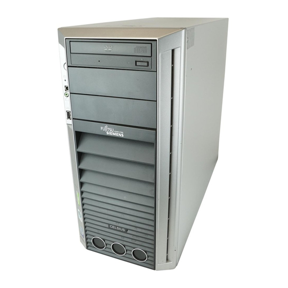
Page 9: Your Celsius
Your CELSIUS..is available with various configuration levels with different hardware and software. You can incorporate operable drives (for example DVD drive) as well as other boards. This manual tells you how to put your device into operation and how to operate it in daily use. This manual applies for all configuration levels. -
Page 10: Notational Conventions
Your CELSIUS... Notational conventions The following symbols are used in this manual: indicates information which is important for your health or for preventing physical damage. indicates important information which is required to use the system properly. ► Texts which follow this symbol describe activities that must be performed in the order shown. -
Page 11: Important Notes
Important notes In this chapter you will find information regarding safety which it is essential to take note of when working with your device. Safety notes Pay attention to the information provided in the "Safety" manual and in the following safety notes. -
Page 12: Energy Saving, Disposal And Recycling
Important notes Energy saving, disposal and recycling Further information can be found on the "User Documentation" or "Drivers & Utilities" DVD provided with your computer. CE mark CE mark for devices without radio component The shipped version of this device complies with the requirements of the EC Guidelines 2004/108/EC "Electromagnetic compatibility"... -
Page 13: Fcc Class B Compliance Statement
● Consult the dealer or an experienced radio/TV technician for help. Fujitsu Siemens Computers GmbH is not responsible for any radio or television interference caused by unauthorized modifications of this equipment or the substitution or attachment of connecting cables and equipment other than those specified by Fujitsu Siemens Computers GmbH. The correction of interferences caused by such unauthorized modification, substitution or attachment will be the responsibility of the user. - Page 14 Important notes A26361-K990-Z120-1-7619, Edition 6...
-
Page 15: Preparing For Use
Preparing for use Please observe the safety information in the "Important notes" chapter. Unpacking and checking the delivery It is recommended not to throw away the original packaging material! It may be required for reshipment at some later date. ► Unpack all the individual parts. -
Page 16: Setting Up The Device
Preparing for use Setting up the device When installing your device, give consideration to the safety notes in the "Safety" manual. The device should only be set up in the intended orientation, i.e. in a vertical position. We recommend that you place your device on a surface with good anti-slip qualities. In view of the multitude of different finishes and varnishes used on furniture, it is possible that the feet of the device will mark the surface they stand on. -
Page 17: Connect The Monitor, Mouse And Keyboard
Preparing for use Unscrewing the base foot (CELSIUS V, CELSIUS R6xx) ► Unscrew the knurled screws (1). ► Pull off the base foot in the direction of the arrow (2). Connect the monitor, mouse and keyboard The ports for the monitor, mouse, and keyboard are on the front and rear of the device. Keyboard port, purple USB port, black Monitor port, blue... -
Page 18: Connecting The Mouse
Preparing for use Connecting the mouse Depending on the equipment level selected, your device will be supplied with a PS/2 mouse or a USB mouse. PS/2 mouse: connecting ► Connect the PS/2 mouse to the PS/2 mouse port of the device. Connecting USB mouse ►... -
Page 19: Connecting The Device To The Mains Voltage
Preparing for use Connecting the device to the mains voltage The device is fitted with a wide voltage range power supply. This means you do not need to set the nominal voltage manually for these devices. Therefore there is no switch available for the voltage setting. -
Page 20: Switching On For The First Time: Installing The Software
Preparing for use Switching on for the first time: installing the software If the device is integrated into a network, the user and server details as well as the network protocol are required during the software installation. Contact your network administrator if you have any questions about these settings. -
Page 21: Installing The Software
Preparing for use Installing the software ► During installation, follow the instructions on screen. ► Consult the operating system manual if there is anything unclear about the requested input data. You will find further information about the system, drivers, utilities, and updates on the "Drivers &... -
Page 22: Ports Provided By The Device
Preparing for use Ports provided by the device The connections are located on the front and back of the device. The ports available on your device depend on the configuration level you have selected. The standard ports are marked with the symbols shown below (or similar). -
Page 23: Connecting External Devices To The Parallel Or Serial Port
Preparing for use Connecting external devices to the parallel or serial port External devices can be connected to the parallel or serial port (e.g. a printer or a modem). ► Connect the data cable to the external device. ► Depending on the device, connect the data cable to the parallel port or the serial port. For an exact description of how to connect external devices to the corresponding port, please see the external device documentation. -
Page 24: Connecting External Devices To The Firewire Port
Preparing for use Connecting external devices to the FireWire port External devices such as digital audio/video devices or other high-speed devices can be connected to the FireWire port. The FireWire port operates at a speed of up to 400 Mbit per second. FireWire devices are hot-pluggable. -
Page 25: Operation
Operation Switching the device on ► If necessary, switch the monitor on (see the operating manual for the monitor). ► Press the ON/OFF switch on the front of the device. The power-on indicator lights green and the device is started. Switching off the device ►... -
Page 26: Indicators Provided By The Device
Operation Indicators provided by the device The indicators are on the front of the casing. Which indicators are available on your device depends on the configuration level you have selected. Hard disk indicator Floppy disk indicator (optional) Power-on indicator SmartCard reader indicator (optional) Drive indicator, e.g. -
Page 27: Keyboard
Operation Drive indicator, e.g. DVD The indicator lights up when the CD-ROM or DVD drive is accessed. You may only remove the DVD when the indicator is dark. Floppy disk indicator (optional) The indicator lights up when the floppy disk drive of the device is accessed. You may only remove the floppy disk when the indicator is unlit. - Page 28 Operation Enter key confirms the marked selection. The enter key is also referred to as the "Return" key. Start key calls up the Windows Start menu. Menu key calls up the menu for the marked item (Windows). Shift key enables upper-case letters and the upper key symbols to be used. Alt Gr (e.g.
-
Page 29: Working With Floppy Disks
Operation Working with floppy disks Follow the instructions supplied by the vendor of the floppy disks. Do not clean the floppy disk drive with cleaning floppy disks. Any attempt would destroy the read/write head in the disk drive within 20 seconds. Write protection tab for a 1.44 MB floppy disk Identification of a 1.44 MB floppy disk or write protect switch on a 120 MB floppy disk To insert a floppy disk... -
Page 30: Settings In Bios Setup
Operation Settings in BIOS Setup In BIOS Setup you can set the system functions and the hardware configuration of the device. When the PC is delivered, the default entries are valid (see "BIOS Setup" manual or manual for the mainboard). You can customise these settings to your requirements in the BIOS Setup. Property and data protection Software functions and mechanical locking offer a broad range of functions for protecting your device and your personal data from unauthorised access. -
Page 31: Bios Setup Security Functions
Operation BIOS setup security functions The Security menu in BIOS Setup offers you various options for protecting your personal data against unauthorised access, e.g.: ● Preventing unauthorised access to the BIOS Setup. ● Preventing unauthorised system access ● Preventing system booting from the diskette drive ●... - Page 32 Operation SystemLock permissions You can initialise a SmartCard with one of the following permissions: System The system starts following entry of the user PIN. You can change the user PIN. Setup You can open and change the BIOS Setup and change the user PIN. System+Setup The system starts following entry of the user PIN.
-
Page 33: Troubleshooting And Tips
Troubleshooting and tips Refer to the safety notes in the "Safety" manual and in the "Preparing for use" chapter when connecting or disconnecting cables. If a fault occurs, try to correct it as described in the following places: ● in this chapter ●... -
Page 34: Troubleshooting
Troubleshooting and tips Troubleshooting Power-on indicator remains unlit after you have switched on your device Cause Troubleshooting The mains voltage supply is faulty. ► Check whether the power cable is plugged properly into the device and a grounded mains outlet. ►... -
Page 35: Screen, Stays Blank
Troubleshooting and tips Screen, stays blank Cause Troubleshooting Monitor is switched off. ► Switch your monitor on. Power saving has been activated ► Press any key on the keyboard. (screen is blank) ► Deactivate the screen saver. If necessary, enter the appropriate password. -
Page 36: No Mouse Pointer Displayed On The Screen
Troubleshooting and tips Cause Troubleshooting Wrong setting for the monitor under ► Restart the device. Windows Vista ► Press F8 while the system is booting. Either the Windows Advanced Start Options menu or the menu for selecting the operating system appears. ►... -
Page 37: The Floppy Disk Cannot Be Read Or Written
Troubleshooting and tips The floppy disk cannot be read or written Cause Troubleshooting The write protection of the floppy disk ► Check that the write protection of the floppy disk or or the floppy disk drive is activated. the floppy disk drive is activated (refer to the "BIOS Setup"... -
Page 38: Hard Disk Contents, Restoring
Troubleshooting and tips Hard disk contents, restoring Should you need to restore your hard disk, the instructions are provided on the case of the "Recovery-CD/DVD" (delivered with your system). Tips Topic Out of system resources If you have too many applications running at once, you may experience problems due to a lack of system resources. -
Page 39: System Upgrades
System upgrades As the device has to be shut down in order to install/deinstall system hardware components, it is a good idea to print out the relevant sections of this chapter. It may be necessary to update the BIOS when carrying out a system expansion or hardware upgrade. -
Page 40: Opening The Casing
System upgrades Opening the casing ► Switch the device off. The device must not be in the energy-saving mode! Please take note of the safety information in the "Important notes" chapter. Pull the power plug out of the mains outlet. Only insert the power plug after you have closed the casing. - Page 41 System upgrades ► Slide the side cover approximately 2 cm (a) in the direction of the arrow (1), until the stop. ► Pull the side cover in the direction of the arrow (2) of the casing. Variant B (version with a locking lever) ►...
-
Page 42: Closing The Casing
System upgrades Closing the casing Variant A (version with knurled screws) ► Hook the side cover into the upper and lower guide rail of the casing in the direction of the arrow (1). Make sure that the side cover is offset by approximately 2 cm (a). ►... - Page 43 System upgrades ► Press the side cover onto the casing (1) at the rear and tighten the two knurled screws (2) with the other hand. ► Return the system unit to its original position. ► Reconnect any disconnected cables (power cord, cables to external devices, etc.). Variant B (version with a locking lever) ►...
-
Page 44: Opening Front Panel
System upgrades Opening front panel ► Open the casing (see "Opening the casing"). ► Detach the three locking tabs on the left side of the front panel (1). ► Fold open the front in the direction of the arrow (2). ►... -
Page 45: Closing Front Panel
System upgrades Closing front panel ► If necessary, hook in the hinge on the right-hand side of the front panel. ► Close the front panel in the direction of the arrow (1) so that the three locking tabs on the left- hand side of the front panel engage (2). -
Page 46: Removing The Side Fan
System upgrades Removing the side fan You will need to remove the side fan inside the casing in order to install boards or upgrade the main memory. ► Open the casing (see "Opening the casing"). ► Release the side fan by pressing the locking hook (a) in the direction of the arrow (1). ►... -
Page 47: Installing The Side Fan
System upgrades Installing the side fan ► Connect the fan cable to the corresponding plug contact on the mainboard (refer also to the manual of the mainboard). ► Position the side fan at a slight angle in the direction of the arrow (1) and hook the fan lugs into the cutouts on the cross piece. -
Page 48: Installing Front Fan (Celsius M)
System upgrades Installing front fan (CELSIUS M) You must install a front fan when converting the hard disks to SCSI hard disks. Securing front fan on fan bracket ► Lay the fan on the fan bracket in the direction of the arrow (1). When doing so, ensure the proper rotating and air-flow direction. -
Page 49: Removing Front Fan (Celsius M)
System upgrades ► Press the green expansion rivet (2) into the hole on the casing. ► Secure the fan by pressing the green expansion rivet (2) into the casing until the tip of the expansion rivet is spread again. ► Close the front panel (see "Closing front panel"). -
Page 50: Removing Ventilation Duct (Celsius V)
System upgrades Removing ventilation duct (CELSIUS V) Before you can upgrade the main memory or the processor, or before you can replace the processor or the lithium battery, you must remove the ventilation duct. ► Unlock the ventilation duct by pressing locking hooks in the direction of the arrow (1). ►... -
Page 51: Installing Ventilation Duct (Celsius V)
System upgrades Installing ventilation duct (CELSIUS V) When routing the fan cable, make sure that it is not kinked or pinched. When fitting the ventilation duct, be careful not to damage the processor cooler(s) on the mainboard. ► Reconnect the fan cables if required. ►... -
Page 52: Removing Ventilation Duct (Celsius M)
System upgrades Removing ventilation duct (CELSIUS M) Before you can upgrade the main memory or the processor, or before you can replace the processor or the lithium battery, you must remove the ventilation duct. The ventilation duct is permanently connected to the fan. ►... - Page 53 System upgrades ► Pull the ventilation duct and the fan a few millimetres in the direction of the arrow (1) to release the hooks at the back of the casing. ► Remove the ventilation duct and the fan from the casing in the direction of the arrow (2). ►...
-
Page 54: Installing Ventilation Duct (Celsius M)
System upgrades Installing ventilation duct (CELSIUS M) ► Pull the fan cable off the fan before the ventilation duct is installed in the device. ► Connect the fan cable to the corresponding plug contact on the mainboard (refer also to the manual of the mainboard). - Page 55 System upgrades ► Press the lever (a) of the ventilation duct in the direction of the arrow until the lever (a) hooks ► Close the casing (see "Closing the casing"). A26361-K990-Z120-1-7619, Edition 6...
-
Page 56: Removing The Ventilation Duct (Celsius R5Xx)
System upgrades Removing the ventilation duct (CELSIUS R5xx) Before you can upgrade the main memory or the processor, or before you can replace the processor or the lithium battery, you must remove the ventilation duct. ► Release the ventilation duct by pressing the locking hooks in the direction of the arrow (1). ►... -
Page 57: Installing The Ventilation Duct (Celsius R5Xx)
System upgrades Installing the ventilation duct (CELSIUS R5xx) When routing the fan cable, make sure that it is not kinked or pinched. When fitting the ventilation duct, be careful not to damage the processor cooler(s) on the mainboard. ► Slide the ventilation duct in the direction of the arrow (1) into the casing until the locking hooks noticeably engage. -
Page 58: Removing The Cross-Piece
System upgrades Removing the cross-piece To upgrade the main memory or replace the processor you will need to remove the cross-piece. ► Remove the ventilation duct (see "Removing ventilation duct (CELSIUS V)" or "Removing the ventilation duct (CELSIUS R5xx)"). ► Remove the side fan (see "Removing the side fan"). -
Page 59: Installing The Cross-Piece
System upgrades Installing the cross-piece ► Insert the cross-piece into its brackets (a) on the rear of the casing at a slight angle. Make sure that the plexiglass plate of the cross-piece is not trapped between the memory slots. ► Press the cross-piece into the casing in the direction of the arrow (1) until the lugs (b) of the cross-piece hook into the brackets (c) in the casing. -
Page 60: Removing Cover Of Power Supply (Celsius M)
System upgrades Removing cover of power supply (CELSIUS M) On the CELSIUS M the connector P11 is located behind the cover of the power supply. When changing the hard disk equipment, you must remove the cover. ► Unscrew the knurled screw (1). ►... -
Page 61: Installing Cover Of Power Supply (Celsius M)
System upgrades Installing cover of power supply (CELSIUS M) ► Insert the cover into the casing in the direction of the arrow (1). ► Slide the cover in the direction of the arrow as far as it will go (2). ►... -
Page 62: Installing And Removing A Board
System upgrades Installing and removing a board Please take note of the section "Information about boards". The number, position and arrangement of the board slots on the mainboard can be found in the manual for the mainboard. Boards may already be installed on shipment. Installing a board ►... - Page 63 System upgrades ► Push the board up to its slot (1). ► Press the board into the slot so that it engages. ► If necessary, connect the cables. ► Fold the locking rail (3) closed by pressing the clips (2) through the notches on the casing rear panel from the outside until they engage.
-
Page 64: Removing A Board
System upgrades Removing a board ► Open the casing (see "Opening the casing"). ► Remove the fan (see "Removing the side fan"). ► Remove the cross-piece if it is in the way (see "Removing the cross-piece”). ► Disconnect the cables connected to the board. ►... - Page 65 System upgrades ► Push the slot cover into the slot (1). Ensure that the projection (a) on the slot cover engages into the appropriate recess. If it does not, you will find it difficult to close the locking rail. There is a danger of damage. ►...
-
Page 66: Low-Profile Boards
System upgrades Low-profile boards For units with a particularly low overall height, there are so-called low-profile boards with a slot cover with a lower overall height to match the low-profile units. To also install these low-profile boards in normal board slots, you must mount a corresponding slot adapter beforehand Two-piece board slot covers are fitted to the slots intended for low-profile boards. -
Page 67: Installing And Removing Drives
System upgrades Installing and removing drives The casing can accommodate a total of seven drives: ● three accessible drives (two 5¼" drives and one 3½" drive) ● four non-accessible drives (3½" drives) "Accessible drives" are e.g. DVD or CD ROM drives, into which a data carrier can be inserted from outside. - Page 68 System upgrades Wiring diagram for mixed equipment with S-ATA and SCSI/SAS drives (CELSIUS M) CD ROM HD 1 SATA HD 2 HD 3 SCSI/SAS HD 4 If you install two S-ATA drives and two SCSI drives or two SAS drives, you must connect the S-ATA hard disks to the connector P11 and the SCSI/SAS hard disks to the connector P5.
-
Page 69: Removing An Accessible Drive
System upgrades Removing an accessible drive ► Open the casing (see "Opening the casing"). ► Pull the data and the power supply connectors from the desired drive. ► Loosen the screws (1). ► Slide the drive out of the bay in the direction of the arrow (2) from behind. The drive now protrudes slightly out of the casing. - Page 70 System upgrades ► If you are not installing a new drive, slide the empty slide-in insert into the casing until it noticeably engages. ► Secure the empty slide-in module with the screws (2). ► Close the casing (see "Closing the casing"). It may be necessary to modify the entry for the remaining drives in the BIOS Setup .
-
Page 71: Installing An Accessible Drive
System upgrades Installing an accessible drive ► Open the casing (see "Opening the casing"). ► If a slide-in module is fitted, remove this first. To do this, proceed in the same way as when removing an accessible drive (see "Removing an accessible drive"). Do not dispose of the empty slide-in module. -
Page 72: Floppy Disk Drive - Removing And Installing
System upgrades Floppy disk drive - removing and installing Removing the floppy disk drive ► Remove the floppy disk drive (see "Removing an accessible drive"). ► Remove the screws (1) on both sides of the slide-in module. ► Pull the disk drive out of the slide-in module (2). Installing the floppy disk drive ►... -
Page 73: Installing And Removing The Hard Disk Drive
System upgrades Installing and removing the hard disk drive Installing a hard disk drive ► Open the casing (see "Opening the casing"). ► Take the new hard disk drive out of its packaging. ► Only for SCSI drives: Make the required settings on the drive. ►... -
Page 74: Removing A Hard Disk Drive
System upgrades ► CELSIUS M only: Remove the cover of the power supply (see "Removing cover of power supply (CELSIUS M) "). ► Connect the data and power supply cables to the hard disk drive or to the hard disk drives. ►... - Page 75 System upgrades ► Pull the EasyChange rails off the hard disk drive. ► If necessary, make the required settings on the remaining hard disk drive. ► CELSIUS M only: Install the front fan if necessary (see "Installing front fan (CELSIUS M)"). ►...
-
Page 76: Installing/Removing A Smartcard Reader (Optional)
System upgrades Installing/removing a SmartCard reader (optional) You can also install a SmartCard reader in the bay of the floppy disk drive in place of the drive. You can install either a WLAN module or a SmartCard reader in your device. SmartCard reader, installing Screwing SmartCard reader onto carrier ►... - Page 77 System upgrades ► Hook the cover into the openings (1). ► Press the cover in the direction of the arrow (2) until the clips engage. ► Install the insert with the SmartCard reader (see "Installing an accessible drive"). A26361-K990-Z120-1-7619, Edition 6...
-
Page 78: Removing A Smartcard Reader
System upgrades Removing a SmartCard reader ► Remove the insert with the SmartCard reader (see "Removing an accessible drive"). ► Detach the locking mechanisms (1) and remove the bezel (2). ► Remove the screws on both sides of the slide-in module (1). ►... - Page 79 System upgrades ► Install the floppy disk drive again (see "Installing the floppy disk drive"). A26361-K990-Z120-1-7619, Edition 6...
-
Page 80: Installing And Removing A Wlan Module (Optional)
System upgrades Installing and removing a WLAN module (optional) You can install either a WLAN module or a SmartCard reader in your device. Installing WLAN module ► Open the casing (see "Opening the casing"). ► Open the front panel (see "Opening front panel"). Initial installation of a WLAN module The slot on the WLAN module inside of the front panel is protected by a metal cover when the device is shipped. - Page 81 System upgrades Installing WLAN module ► Slide the WLAN module into the slot on the front of the casing in the direction of the arrow (1). Make sure that the screw holes for the screws are aligned. ► Fasten the WLAN module with the screws (2). A26361-K990-Z120-1-7619, Edition 6...
- Page 82 System upgrades ► Thread the USB data cable of the WLAN module through the opening in the direction of the arrow (1). ► Connect the USB data cable of the WLAN module onto the corresponding connector on the mainboard (also see the manual for the mainboard). ►...
-
Page 83: Removing Wlan Module
System upgrades Removing WLAN module ► Open the casing (see "Opening the casing"). ► Open the front panel (see "Opening front panel"). ► Detach the USB data cable of the WLAN module from the mainboard (see the manual for the mainboard). -
Page 84: Extensions To The Mainboard
System upgrades Extensions to the mainboard Details on how you can upgrade the main memory or the processor of your device are provided in the manual for the mainboard. Main memory, upgrading ► Open the casing (see "Opening the casing"). ►... -
Page 85: Battery: Lithium Battery: Changing
System upgrades Battery: lithium battery: changing In order to permanently save the system information, a lithium battery is installed to provide the CMOS-memory with a current. A corresponding error message notifies the user when the charge is too low or the battery is empty. The lithium battery must then be replaced. Incorrect replacement of the lithium battery may lead to a risk of explosion! The lithium battery may be replaced only with an identical battery or with a type recommended by the manufacturer. - Page 86 System upgrades A26361-K990-Z120-1-7619, Edition 6...
-
Page 87: Technical Data
Operating (3K2) 15°C ..35°C Transport (2K2) -25°C ..60°C Condensation in operating must be avoided. The data sheets of these devices contains further technical data. You will find the data sheets on the internet at www.fujitsu-siemens.com . A26361-K990-Z120-1-7619, Edition 6... - Page 88 Technical data A26361-K990-Z120-1-7619, Edition 6...
-
Page 89: Index
Index Connecting device 11 keyboard 10 3 1/2-inch drive 60 mouse 10 PS/2 mouse 10 standard keyboard 10 5 1/4-inch drive 60 USB keyboard 10 Connecting FireWire devices 16 Connecting standard keyboard 10 Access permission, SmartCard 23 Contents of delivery 7 Accessible drive Cover, installing 54 installing 64... - Page 90 Index Interfaces 14 Electromagnetic compatibility 4 EMC, Electromagnetic compatibility 59 Energy saving 4 Kensington Lock 22 Ergonomic, video workstation 8 Error Alt Gr 20 date 30 Control 20 device 26 Ctrl 20 mouse 28 cursor keys 19 screen 27 Enter 20 time 30 enter key 20 Error message 30...
- Page 91 Index switching on 12, 17 PS/2 mouse port 14 transporting 3 Monitor port 14 Mouse Ready-to-operate 17 connecting 10 Recycling 4 error 28 Removing front fan (CELSIUS M) 42 port 9 Replacing Mouse Cursor 28 lithium battery 78 Mouse port 14 Retransportation 3 New installation, software 30 Safety notes 3...
- Page 92 Index device 26 mouse 28 Ventilation 8 screen 27 Ventilation duct Troubleshooting 25 installing 44, 47, 50 removing 43, 45, 49 Video devices, connecting 16 Video workstation 8 USB 9 Universal Serial Bus 14 USB devices connecting 15 Warm boot 20 USB port 10 WLAN module connecting devices 15...