
Related Manuals for Fujitsu Siemens Computers PRIMERGY B120


Summary of Contents for Fujitsu Siemens Computers PRIMERGY B120
- Page 1 P R I M E R G Y B 1 2 0 P R I M E R G Y B 1 2 0 P R I M E R G Y B 1 2 0 P R I M E R G Y B 1 2 0 Intel-based Server Systems OPERATING MANUAL OPERATING MANUAL...
- Page 2 Further information can be found in the guarantee booklet or in the service address booklet. The latest information on our products, tips, updates, etc., can be found on the Internet under: http://www.fujitsu-siemens.com...
- Page 4 Este manual ha sido impreso sobre papel reciclado. Questo manuale è stato stampato su carta da riciclaggio. Denna handbok är tryckt på recyclingpapper. Dit handboek werd op recycling-papier gedrukt. Herausgegeben von/Published by Fujitsu Siemens Computers GmbH A26361-K646-Z102-1-7619 A26361-K646-Z102-1-7619 A26361-K646-Z102-1-7619 A26361-K646-Z102-1-7619 Bestell-Nr./Order No.:...
- Page 5 Introduction Important notes PRIMERGY B120 Installation Preparation for use and operation Opening and closing the server Operating Manual Property and data protection Troubleshooting and tips System components and expansions Index February 2001 edition...
- Page 6 All other trademarks referenced are trademarks or registered trademarks of their respective owners, whose protected rights are acknowledged. Copyright ã Fujitsu Siemens Computers GmbH 2001 All rights, including rights of translation, reproduction by printing, copying or similar methods, even of parts are reserved.
-
Page 7: Table Of Contents
Contents 1 Introduction ..........................1 1.1 Features ............................1 1.2 Notational conventions ........................3 1.3 Technical data ..........................3 2 Important notes ..........................5 2.1 Safety ............................5 2.2 CE certificate ..........................7 2.3 FCC Class B Compliance Statement ...................8 2.4 Transporting the server........................8 2.5 Disposal and recycling.........................9 3 Installation .......................... - Page 8 Contents 7.8 Time and/or date is not correct....................41 7.9 System does not boot ....................... 41 7.10 Drives "dead" at system boot ....................42 7.11 Added drive defective......................42 7.12 Error messages on the screen ....................42 8 System components and expansions ..................
-
Page 9: Introduction
Introduction The PRIMERGY B120 server is an Intel-based server for small and medium-sized networks and can be used as a tower (floorstand) or rack servers. Conversion to the respective other version is possible with an optional conversion kit. The PRIMERGY B120 Server offers a high level of failure protection and availability through highly developed hardware and software components. - Page 10 Service and Support PRIMERGY devices are service-friendly and modular, thus enabling quick and simple maintenance. The flash EPROM program supplied with the Fujitsu Siemens utilities supports fast BIOS update. With the optional Remote Test and Diagnosis System RemoteView (chipDISK), long-distance maintenance and service (remote) can also be performed on the servers of the PRIMERGY series.
-
Page 11: Notational Conventions
Notational conventions Introduction Notational conventions The meanings of the symbols and fonts used in this manual are as follows: Pay particular attention to texts marked with this symbol. Failure to observe this warning endangers your life, destroys the system, or may lead to loss of data. - Page 12 Introduction Technical data Standards Product safety and ergonomics IEC 60950 / EN 60950 UL 1950, CSA 22.2 No. 950 Electromagnetic compatibility FCC class B (standard power supply) EN 55022, EN 61000-3-2, EN 61000-3-3 Emitted interference EN 50024 RF interference suppression CE mark as per EC guideline Low-Voltage Directive 73/23/EWG Electromagnetic Compatibility 89/336/EEC...
-
Page 13: Important Notes
Important notes In this chapter you will find information regarding safety which it is essential to take note of when working with your server. The manufacturer's notes contain helpful information on your server. Safety The following safety notes are also provided in the manual "Safety, Guarantee and Ergonomics", which contains additional information about guarantee and ergonomics. - Page 14 Important notes Safety Poper operation of the system, warranty features WARNING! Proper operation of the device (in accordance with IEC 60950/DIN EN60950) is only ensured if the casing is completely assembled and the rear covers have been put in place (electric shock, cooling, fire protection, interference suppression).
-
Page 15: Ce Certificate
CE certificate Important notes Modules with electrostatic sensitive components Boards with electrostatic sensitive devices (ESD) may be identified by labels. When you handle boards fitted with ESDs, you must observe the following points under all circumstances: You must always discharge yourself (e. g. by touching a grounded object) before working. The equipment and tools you use must be free of static charges. -
Page 16: Fcc Class B Compliance Statement
Consult the dealer or an experienced radio/TV technician for help. Fujitsu Siemens Computers GmbH is not responsible for any radio or television interference caused by unauthorized modifications of this equipment or the substitution or attachment of connecting cables and equipment other than those specified by Fujitsu Siemens Computers GmbH The correction of interference caused by such unauthorized modification, substitution or attachment will be the responsibility of the user. -
Page 17: Disposal And Recycling
Tel.: +49 5251 8180-10 Fax: +49 5251 8180-15 Further information on environmental protection The Fujitsu Siemens Computers GmbH representative for environmental protection will be pleased to answer any further questions you may have concerning environmental protection. Fujitsu Siemens Computers GmbH Environmental Protection Werner-von-Siemens-Straße 6... -
Page 19: Installation
Installation Please take note of the safety information in the chapter "Important notes". Do not expose the server to extreme environmental conditions (see section "Technical data"). Protect it from dust, humidity and heat. There must be a clearance of at least 200 mm in front of and behind the server to ensure adequate ventilation. -
Page 20: Instructions On Connecting And Disconnecting Cables
Installation Instructions on connecting and disconnecting cables Instructions on connecting and disconnecting cables Be sure to read the documentation on the external devices before connecting them. Do not connect or disconnect cables during a thunderstorm. Always take hold of the actual plug. Never unplug a cable by pulling the cable itself. Connect and disconnect the cables in the order described below. -
Page 21: Connecting The Tower Server To The Line Voltage
Setting up the tower server Installation 3.4.1 Connecting the tower server to the line voltage The server is equipped with a permanently installed standard power supply. Two standard designs are available for the power supply. The only difference between them is that the connection panel is rotated 180°. -
Page 22: Connecting The Monitor To The Line Voltage
Installation Installing rack-server in/removing from rack 3.4.2 Connecting the monitor to the line voltage On the server with the standard power supply it is possible to connect the power cable of the monitor to the server. Ê Depending on the connector and the power supply, plug the monitor's power cable into either the server (1) or a grounded power outlet (2). -
Page 23: Mounting The Slide-In Module
Installing rack-server in/removing from rack Installation 3.5.1 Mounting the slide-in module Ê Screw together the front panel and the bottom tray to form a slide-in module (1 + 2). Ê Place the server in the slide-in module with the right side facing downward and somewhat offset toward the rear. - Page 24 Installation Installing rack-server in/removing from rack Ê Push the server up to the front panel. Ê Secure the server at the back to the bottom tray with the angled mounting bracket (1 + 2). A26361-K646-Z102-1-7619...
-
Page 25: Installing The Slide-In Module
Installing rack-server in/removing from rack Installation 3.5.2 Installing the slide-in module The server requires five height units. The sliding rails are mounted in the bottom height unit. One height unit is equal to 4.445 cm = 1 ¾ inches. Fitting spring nuts ca 45°... - Page 26 Installation Installing rack-server in/removing from rack Mounting cage nuts Ê Mount the cage nut with the lower cage section in the corresponding mounting hole as shown in the illustration (1). Ê Then pry and pull the upper section of the cage nut into the mounting hole with the tool supplied (2).
-
Page 27: Connecting The Rack Server To The Line Voltage
Installing rack-server in/removing from rack Installation Place the server on the slide rails in the rack (1) and secure the server with the four knurled screws in the rack (2). 3.5.3 Connecting the rack server to the line voltage The server is equipped with a permanently installed standard power supply. Two standard designs are available for the power supply. -
Page 28: Prepare The Keyboard
Installation Prepare the keyboard Ê Plug the power cable of the server into the server (1) and into a free electrical outlet of the multi-outlet assembly in the rack (2) (see technical manual for rack). Guide the cable through the cable routings of the rack. Prepare the keyboard Ê... -
Page 29: Connecting Devices To The Server
Connecting devices to the server Installation Connecting devices to the server All ports are on the rear of the server. Which ports are available on your server depend on the boards installed. The standard ports are marked with symbols and some are color-coded. Tower Rack 1 = Mouse... - Page 30 Installation Connecting devices to the server If you connect the monitor power cable to the monitor power outlet of a server with the standard power supply, then the current consumption of the monitor may not exceed 1.5 A (at 230 V) or 3 A (at 115 V). The rated current for the monitor is also given on the monitor itself or in the Operating Manual for the monitor.
-
Page 31: Preparation For Use And Operation
Preparation for use and operation Please take note of the safety information in the chapter "Important notes". Work steps which are identical for the tower and rack version are only described for the tower version. For details on the rack variant, please see the Technical Manual for the rack. - Page 32 Preparation for use and operation Unlocking/locking the tower server Enabling access to the hard disk drives Ê Unlock the server (1). Ê Slide up the drive cover as far as possible (2). Ê Remove the hard disk cover toward the front (3 + 4). The hard disk cover is remounted and the server connected in the reverse order.
-
Page 33: Operation Controls
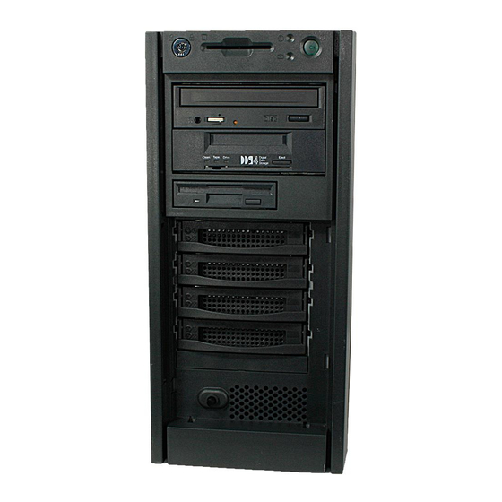
Operation controls Preparation for use and operation Operation controls 1 = Floppy disk drive with power-on indicator 5 = IDE busy indicator 2 = CD-ROM drive with power-on indicator 6 = Message indicator 3 = Lock 7 = ON/OFF switch with power-on indicator 4 = Chipcard reader with power-on indicator 8 = Hard disk indicator (optional) (optional) -
Page 34: Operation Controls
Preparation for use and operation Operation controls 4.2.1 Operation controls Lock unlocks or locks the server. ON/OFF switch switches the server to ready-to-operate or on. The ON/OFF switch and the main switch do not disconnect the server from the line voltage. -
Page 35: Switching The Server On And Off
Switching the server on and off Preparation for use and operation Switching the server on and off If after switching on the server there is nothing but flickering stripes on the screen, switch the server off immediately (see "Troubleshooting and tips"... - Page 36 Preparation for use and operation Switching the server on and off Server is switched off The main switch (a) is in position 0 and the power-on indicator does not light. The ON/OFF switch (b) is inoperative. The screen socket on the server is dead. Server is ready for operation (stand-by state) The main switch (a) is in position I and the power-on indicator (c) does not light.
-
Page 37: Configuring The Server
Configuring the server Preparation for use and operation Configuring the server This section contains information of the server configuration and on installing the operating system. Make sure that the energy saving functions are disabled in the BIOS Setup during server operation. 4.4.1 Configuration with ServerStart With the ServerStart CD provided you can configure the server and install the operating system in a convenient manner. -
Page 38: Locking The Tower Server
Preparation for use and operation Locking the tower server Locking the tower server Fitting the hard disk cover Ê If the server is locked, unlock it (1). Ê Slide the drive cover completely upwards (2). Ê Fit the hard disk cover (3 + 4). Ê... -
Page 39: Cleaning The Server
Cleaning the server Preparation for use and operation Locking the server Ê Slide the drive cover upwards (1). Ê Lock the server (2). Cleaning the server Switch the server off and pull the power plug out of the grounded-contact power socket. Do not clean any interior parts yourself, leave this job to a service technician. -
Page 41: Opening And Closing The Server
Opening and closing the server Please take note of the safety information in the chapter "Important notes". Ê Switch the server off. Pull the power plug out of the power outlet. Ê Disconnect all cables on the rear that are obstructing you. Opening and closing the tower server Ê... -
Page 42: Opening And Closing The Rack Server
Opening and closing the server Opening and closing the rack server Opening and closing the rack server Ê Release the four knurled screws (1) and pull the server carefully out of the rack up to the stop (2). Ê Press the locking springs on both sides of the server (1) and carefully remove the server from the rack (2). - Page 43 Opening and closing the rack server Opening and closing the server Ê Unlock the server (1). Ê Unscrew the two knurled screws (2). Ê Push the top cover approx. 2 cm backwards (3). Ê Lift off the top cover upwards (4). Ê...
-
Page 45: Property And Data Protection
Property and data protection The tower server is protected against unauthorized opening with the lock. Regardless of this, two intrusion detection switches are employed with which the ServerView program recognizes and logs any removal of the housing side cover and the hard disk cover. To prevent the tower server from being stolen, it can be secured to a fixed object with a steel cable run through the tab on the back. -
Page 47: Troubleshooting And Tips
Troubleshooting and tips Take note of the safety notes in the manual "Safety and Ergonomics" and in the chapter "Installation", when you connect or disconnect cables. If a fault occurs, try to correct it according to the following procedures. These are described: in this chapter in the documentation of the connected devices in the help systems of the software used. -
Page 48: Flickering Stripes On The Monitor Screen
Troubleshooting and tips Flickering stripes on the monitor screen Brightness control is set to dark Ê Set the brightness control to bright. For detailed information, please refer to the Operating Manual supplied with your monitor. Power cable or monitor cable not connected Ê... -
Page 49: No Mouse Pointer Displayed On The Screen
No mouse pointer displayed on the screen Troubleshooting and tips No mouse pointer displayed on the screen Mouse driver not loaded Ê Check whether the mouse driver is properly installed and is present when the application program is started. Detailed information can be found in the User Guides of the mouse, the operating system or the application program. -
Page 50: Drives "Dead" At System Boot
Troubleshooting and tips Drives "dead" at system boot 7.10 Drives "dead" at system boot SCSI drives are reported as "dead" at system boot. This error message may occur when the server has a disk array controller. SCSI cabling incorrect Ê Make sure the SCSI cable connection and the SCSI channel assignment still correspond to the original state. -
Page 51: System Components And Expansions
System components and expansions This chapter describes how to modify your server hardware (e.g. installing or removing boards or accessible drives). Work steps which are identical for the tower and rack version are only described for the tower version. Memory and processor upgrading as well as replacement of the lithium battery are described in the Technical Manual for the system board. -
Page 52: Scsi Hard Disk Drives
System components and expansions The SCSI hard disk subsystem The following applies if SCSI hard disk drives are operated on a disk array controller: RAID level 0 and 7 Rebuild is not possible. If a hard disk fails, its data is lost. RAID level 1 and 5 without standby hard disk Rebuild on the new disk is carried out automatically when the old disk is swapped. -
Page 53: Replacement Of Scsi Hard Disk Drive During Operation
The SCSI hard disk subsystem System components and expansions Function of the indicators Green indicator The green LED lights up when the hard disk is accessed. You may not replace the hard disk at this time! Orange indicator The orange indicator flashes when, in conjunction with a Disk Array Controller, the configuration is determined or a rebuild is done. -
Page 54: Installing/Removing A Scsi Hard Disk Drive
System components and expansions The SCSI hard disk subsystem 8.1.3 Installing/removing a SCSI hard disk drive If a hard disk drive is to be installed in a bay in which no hard disk drive is previously installed, then the blind insert must be removed from this bay beforehand. Ê... -
Page 55: Scsi Platter For Four 1-Inch Hard Disk Slide-In Modules
The SCSI hard disk subsystem System components and expansions 8.1.4 SCSI platter for four 1-inch hard disk slide-in modules The hot-replace SCSI platter connects up to four 1-inch hard disk slide-in module with the SCSI controller and supports Ultra3 Wide SCSI (U160 SCSI). SCSI ID 3 SCSI ID 2 SCSI ID 1... -
Page 56: Accessible Drives
System components and expansions Accessible drives Accessible drives The server accommodates three accessible drives (two 5 ¼-inch drives and one 3 ½-inch drive). As shipped, two drives are fitted: a 3 ½-inch floppy disk drive and a CD-ROM drive. When installing or removing drives, the following points must be observed for the configuration depending on the drive type (IDE or SCSI): IDE drive The drive must be entered in the BIOS Setup (see description of BIOS Setup). -
Page 57: Installing/Removing An Accessible 5 ¼-Inch Drive
Accessible drives System components and expansions 8.2.1 Installing/Removing an accessible 5 ¼-inch drive Ê Shut down the operating system. Ê Switch off the server, and disconnect it from the network. Switching off the server does not disconnect the device from the network. To completely disconnect the device from the network, remove the power plug from the line voltage. -
Page 58: Changing The Floppy Disk Drive
System components and expansions Accessible drives 8.2.2 Changing the floppy disk drive Ê Shut down the operating system. Ê Switch off the server, and disconnect it from the network. Switching off the server does not disconnect the device from the network. To completely disconnect the device from the network, remove the power plug from the line voltage. -
Page 59: Removing/Installing Boards
Removing/installing boards System components and expansions Removing/installing boards Before installing or removing a board, please read the documentation supplied with the board. Ê Shut down the operating system. Ê Switch off the server, and disconnect it from the network. Ê Open the server (see "Opening and closing the server"). -
Page 60: Chipdisk For Remoteview
System components and expansions chipDISK for RemoteView chipDISK for RemoteView To use RemoteView, the remote test and diagnosis system, on the server, a RemoteView chipDISK is available for the PRIMERGY B120 server as an option. The RemoteView chipDISK is equipped with an IDE interface and is mounted in the server on the side of the drive cage on two spacer sleeves. -
Page 61: Configuring The Chipdisk
chipDISK for RemoteView System components and expansions Ê Screw the chipDISK onto the side of the drive cage (1). Ê Connect the IDE data cable provided to the chipDISK (1) and to the primary IDE interface of the system board. Ê... -
Page 62: Replacing The System Fan
System components and expansions Replacing the system fan Replacing the system fan The server system fan can easily be replaced during servicing. Ê Open the server (see "Opening and closing the server"). Ê Pull the cable off the fan (1). Ê... -
Page 63: Adapter Module
Adapter module System components and expansions Adapter module The adapter module is located at the front in the base of the house. In addition to the system board it provides the following functions: System fan control Device ID Error logging 1 = DIP switch for setting the limit 3 = System fan connector temperatures for fan control;... -
Page 65: Index
Index Controls Courier 5 ¼-inch drive installing removing Data protection Data, technical Date, not correct Defective drive Accessible drive Device ID installing Devices, connecting removing Diagnostic system Adapter module Dimensions ASR&R DIP switch Disk Array Controller 1, 29, 43, configuring Battery defective drive replacing... - Page 66 Index system does not boot rack server time Interfaces wrong date Italics Error logging Extensions, system board Keyboard cleaning connecting Fan, exchanging Keyboard port FCC statement Features Flickering stripes on the monitor screen Label, on plastic casing parts Floppy disk drive LAN port changing Light-emitting diode...
- Page 67 Index Opening hard disk drive 29, Operating system installing Security measures not starting Security standards Operation Serial port Overview Server features opening ports and slots switches itself off Server management ServerStart 2, ServerView Packing material 9, Setting up Parallel port tower server PDA technology Side cover...
- Page 68 Index drive reported as dead Ultra3 Wide SCSI flickering screen Unlocking, tower server floppy disk cannot be read/written USB port message on the screen no mouse pointer screen Ventilation gaps screen display drifts server server switches itself off Wakeup On LAN (WOL) system does not boot Warranty features Troubleshooting and tips...