
Related Manuals for Ericsson RX8200


Summary of Contents for Ericsson RX8200
-
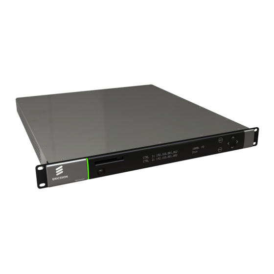
Page 1: Rx8200 Advanced Modular Receiver
RX8200 Advanced Modular Receiver Software Version 4.3.2 USER GUIDE EN/LZT 790 0009 R1A... - Page 2 The contents of this document are subject to revision without notice due to continued progress in methodology, design and manufacturing. Ericsson shall have no liability for any error or damage of any kind resulting from the use of this document.
-
Page 3: Table Of Contents
Contents Contents Introduction.................... 5 Who Should Use this User Guide? ............5 What Equipment is Covered by this User Guide? ........5 Hardware and Software Options ............. 5 Installing the Equipment ............... 9 Introduction....................9 Operating Voltage..................9 Power Cable and Earthing............... 9 Rear Panel Connectors ................. - Page 4 Contents List of Figures Figure 1 Rear Panel Connectors ................10 Figure 2 Front Panel LEDs and Pushbuttons ............17 Figure 3 Front Panel Menus .................19 Figure 4 Input Card Front Panel Menus ...............20 Figure 5 Web Page Overview (Typical)..............24 Figure 6 About dialog (Typical)................24 Figure 7 Status Web Page ...................26...
-
Page 5: Introduction
Reference Guide companion document which is issued on CD. Warning! Do not remove the covers of this equipment. Hazardous voltages are present within this equipment and may be exposed if the covers are removed. Only Ericsson trained and approved service engineers are permitted to service this equipment. Caution! Unauthorized maintenance or the use of non-approved replacements may affect the equipment specification and invalidate any warranties. -
Page 6: Table 2 Rx8200 Hardware Options
Introduction Table 2 RX8200 Hardware Options Marketing Code Price Object Supply Object Description Number Number RX8200/HWO/DVBS2 FAZ 101 0113/5 ROA 128 3757 DVB-S2 Input Card RX8200/HWO/IP/GIGE FAZ 101 0113/12 ROA 128 3761 Gigabyte 100/1000BaseT Ethernet RX8200/HWO/G703 FAZ 101 0113/8 ROA 128 3763 G.703 ATM Input Card RX8200/HWO/MP2/422 FAZ 101 0113/15... - Page 7 Introduction Marketing Code Price Object Supply Object Description Number Number RX8200/SWO/MP2/MP4/SD/HD FAZ 101 0113/41 FAT 102 0156 MPEG-2 & MPEG-4 HD and SD Decode RX8200/SWO/SING/SERVFILT FAZ 101 0113/53 FAT 102 0181 Single Service Filtering RX8200/SWO/MULT/SERVFILT FAZ 101 0113/47 FAT 102 0182 Multi-Service Filtering RX8200/SWO/TTV FAZ 101 0113/58...
- Page 8 Introduction Marketing Code Price Object Supply Object Description Number Number 1080i or 720p) RX8200/SWO/XCONV FAZ 101 0113/55 FAT 102 0175 Cross-conversion RX8200/SWO/FSYNC FAZ 101 0113/33 FAT 102 0160 Frame Sync RX8200/SWO/4AUD FAZ 101 0113/20 FAT 102 0180 4 x Audio Capacity RX8200/SWO/LDELAY FAZ 101 0113/38 FAT 102 0173...
-
Page 9: Installing The Equipment
Warning! Do not remove the covers of this equipment. Hazardous voltages are present within this equipment and may be exposed if the covers are removed. Only Ericsson trained and approved service engineers are permitted to service this equipment. Operating Voltage... -
Page 10: Rear Panel Connectors
Installing the Equipment Warning! The Technical Earth is not a Protective earth for electric shock protection. This unit must be correctly earthed through the molded plug supplied. If the local mains supply does not have an earth conductor do not connect the unit. Contact Customer Services for advice. -
Page 11: Connecting The Receiver To The Power Supply
Installing the Equipment Type of Connector Description ASI/SD-SDI/HD-SDI 75 Ω BNC connector for ASI or SDI (user selectable) OUT 1 , 2 & 3 output feeds. 75 Ω BNC connector for ASI input feed. ASI INPUT CONTROL 1 & 2 8-way RJ-45 connectors for 10/100BaseT Ethernet control and monitoring. -
Page 12: Quick Start Guide: Connect-Power-Configure
Quick Start Guide: Connect-Power-Configure Quick Start Guide: Connect-Power-Configure Connecting the Receiver The following points should be noted when making signal connections to the receiver: • For models with option RX8200/HWO/DVBS2 fitted, connect the incoming satellite RF feed to the rear panel connector marked RF IN 1 - 4. •... -
Page 13: Configuring The Inputs
Quick Start Guide: Connect-Power-Configure 2. Switch on the AC power supply to the unit at the wall or rack outlet. Note: The RX8200 Receiver does NOT contain a power on/off switch. 3. After a short period of initialization the following screen is displayed on the Front Panel: INITIALIZING 4.3.2 (Bank 0) - Page 14 Quick Start Guide: Connect-Power-Configure 8. Set the set the LNB power output level A description of each of these User Settings can be found in the Reference Guide. Note: If the unit has successfully locked to the incoming feed, then the TS Lock value in menu Input should be LOCKED.
-
Page 15: Selecting A Decode Service (Program)
Quick Start Guide: Connect-Power-Configure 9. Set up Sync Count to Lock/Sync Miss Sample Size 10. Set up Sync Miss Limit. A description of each of these User Settings can be found in the Reference Guide. Note: If the unit has successfully locked to the incoming feed, then the TS Lock value in menu Input should be LOCKED. -
Page 16: Configuring For Single-Service Decryption
Quick Start Guide: Connect-Power-Configure • The unit will automatically decode the first two audio components that it finds within the selected service. • Alternative audio components may be selected from the service tab on the Web Control interface. Configuring for Single-service Decryption When configuring for Single-service Decryption the following points should be observed: •... -
Page 17: Front Panel Control
Front Panel Control Front Panel Control Introduction The Front Panel display and keypad may be used to configure, control and monitor the receiver when an external control system is not used. Note: A list of receiver user settings that may be viewed or changed via the front panel and those that may be viewed or changed via the external web browser interface can be found in the Reference Guide. - Page 18 Front Panel Control 4.3.2 A 2-line x 40-character back-lit dot-matrix Liquid Crystal Display (LCD) displays various menus and settings. The menus and setting available will vary depending on which options have been enabled through the purchase of a suitable license. 4.3.3 Arrow Pushbuttons Four arrow pushbuttons (or keys) are used to navigate through the front panel LCD...
-
Page 19: Front Panel Menus
Front Panel Control Front Panel Menus An overview of the available Front Panel menus is shown below. The menus and settings available will vary depending on which receiver model is being used and which options have been enabled through the purchase of a suitable license. Note: The menu structure is subject to change as further functionality is added. -
Page 20: Figure 4 Input Card Front Panel Menus
Front Panel Control 2.2 Select Satellite Input 2.2 I/P Input Card 2.2 C onfigure G.703 Input — 2.2.1 Status — 2.2.1 Status — 2.2.1 Status 2.2.1.1 Current Port 2.2.1.1 Card Alarm Status 2.2.1.1 Lock Status 2.2.1.2 Encapsulation 2.2.1.2 Physical Alert Status 2.2.1.2 Error Ratio/Signal Level 2.2.1.3 Number of Columns/Rows 2.2.1.3 MPEG Alert Status... -
Page 21: Menu Structure
Front Panel Control 4.4.1 Menu Structure The Front Panel menus and sub-menus, available on the LCD, provide the configuration parameters that may be viewed, selected and/or modified. • System - Provides sub-menus for viewing/configuring the receiver hardware and access parameters. Network –... - Page 22 Front Panel Control Director – Enables configuration of Director Conditional Access parameters, such as: ID numbers, download status and the facility to reset or change the PIN number. • Output Menu - Provides sub-menus for viewing/configuring the receiver output parameters. Output Selection - Enables selection of the required output type.
-
Page 23: Web Browser Control
A personal computer (PC) running a Web Browser can be used to configure, control and monitor the receiver remotely. The following web browsers have been tested: • Microsoft Internet Explorer (This is the only browser supported by Ericsson) • Mozilla Firefox (Functional but unsupported) •... -
Page 24: Figure 5 Web Page Overview (Typical)
Web Page Overview (Typical) • Header – The header of the web page displays the Ericsson logo and the unit model number name. At the right-hand side of the header an About button which, when clicked, displays an information dialog about the unit, including the software version number. - Page 25 Web Browser Control web page. When you switch between tabs, the browser remembers the path for each tab. • Navigation Path – The web pages are organized into a tree-like structure, like the directory on a computer. The current complete navigation path is always displayed at the top of the web page, which shows the route taken to the currently displayed web page.
-
Page 26: Web
Web Browser Control Web Pages 5.3.1 Status This web page shows a number of top-level parameters indicating the current status of the receiver. Figure 7 Status Web Page 5.3.2 Device Info The Device Info web page provides access to system-level settings for the receiver and can be used to enable the Front Panel Lockout Facility and initiate Rebooting functions. -
Page 27: Figure 8 Device Info Web Page
Web Browser Control Figure 8 Device Info Web Page This page also provides buttons to the following further web pages: • Build – provides details of equipment build and version numbers. No user- editable fields. • Environment – provides details of the physical environment of the equipment such as temperature and fan speed. - Page 28 Web Browser Control 5.3.3 Alarms The Alarms web page provides access to the alarms settings for the receiver. The contents of this page are composed mainly of fields with drop-down menus which allow the setting or masking of various alarms and check boxes which can be used to activate relay mapping.
-
Page 29: Figure 9 Alarms Web Page
BISS - allows the user to view and modify the settings for Basic Interoperable Scrambling System (BISS). These are Mode 1, Mode E Fixed, Mode E Ericsson, Mode E User One, Mode E User Two. Mode 1 uses an unencrypted key for the BISS key. -
Page 30: Figure 11 Ca Web Page
Web Browser Control • RAS - allows the user to select Digital Satellite News Gathering (DSNG) or Fixed Key mode and input a 7-digit DSNG key. Figure 11 CA Web Page 5.3.6 Input The Input Web Page provides access to the parameters of the various inputs to the receiver. -
Page 31: Figure 12 Input Web Page (Satellite Input Card Fitted)
Web Browser Control Figure 12 Input Web Page (Satellite Input Card fitted) Click on the Satellite Input button on the Input page to display a further sub page. Figure 13 Input > SAT Input Sub Page (Satellite Input Card fitted) The only field which may be edited by the user is the RF Selection field which allows selection of the appropriate RF Input. -
Page 32: Figure 14 Input Web Page (Ip Card Fitted)
Web Browser Control If the I/P Input Card is fitted, the following web page is displayed. Figure 14 Input Web Page (IP Card fitted) Click on the IP Input button on the Input page to display a further sub page. 32 (44) EN/LZT 790 0009 R1A 2011-03-30... -
Page 33: Figure 15 Input > Ip Input Sub Page (Ip Card Fitted)
Web Browser Control Figure 15 Input > IP Input Sub Page (IP Card fitted) If the G.703 Input Card is fitted, the following web page is displayed. Figure 16 Input Web Page (G.703 Input Card fitted) EN/LZT 790 0009 R1A 2011-03-30 33 (44) -
Page 34: Figure 17 Input > G.703 Input Sub Page (G.703 Input Card Fitted)
Web Browser Control Click on the G703 Input button on the Input page to display a further sub page. Figure 17 Input > G.703 Input Sub Page (G.703 Input Card fitted) 5.3.7 Service Plus The Service Plus web page provides access to the various encryption and encoding services available to the receiver. -
Page 35: Figure 19 Decode Web Page
Web Browser Control • VBI-VANC - gives access to Vertical Blanking Interval-Vertical Ancillary Data Space (VBI-VANC) parameters. • Splice - gives access to the splice operation parameters. • DVB Subtitles - gives access to the Digital Video Broadcasting (DVB) subtitles parameters. -
Page 36: Figure 20 Output Web Page
Web Browser Control 5.3.9 Output The Output web page provides access to the output feed parameters of the receiver. Figure 20 Output Web Page 5.3.10 Download The Download web page provides access to the over air download status of the receiver. -
Page 37: Figure 21 Download Web Page
Web Browser Control Figure 21 Download Web Page 5.3.11 SNMP This page gives access to the Simple Network Management Protocol (SNMP) parameters for the receiver, including protocol selection and MIB parameters. Figure 22 SNMP Web Page 5.3.12 Presets The Presets web page gives access to a list of 40 preset configurations. This feature may be used to store input (tuning) parameters and service selection (service id only) in order that settings do not have to be re-entered when changes are made. -
Page 38: Figure 23 Presets Web Page
Web Browser Control Figure 23 Presets Web Page 5.3.13 Save/Load The Save/Load web page provides a range of configuration download and upload facilities, including saving and restoring unit configuration, saving unit MIB files, saving alarm log files and saving splice log files. 38 (44) EN/LZT 790 0009 R1A 2011-03-30... -
Page 39: Figure 24 Save/Load Web Page
Web Browser Control Figure 24 Save/Load Web Page 5.3.14 Help The Help web page gives access to a Web Interface User Guide which provides a brief description of the interface functionality. Figure 25 Help Web Page EN/LZT 790 0009 R1A 2011-03-30 39 (44) -
Page 40: Equipment Packaging
Equipment Packaging Equipment Packaging Packaging Statement The outer carton and any cardboard inserts are made from 82% recycled material and are fully recyclable. ® ® The Stratocell or Ethafoam 220 polyethylene foam inserts can be easily recycled with other low density polyethylene (LDPE) materials Packaging Markings The symbols printed on the outer carton are described below: Handle with care. -
Page 41: Materials Declarations
“Environmentally Friendly Use Period (EFUP)”: the time the product can be used in normal service life without leaking the hazardous materials. Ericsson expects the normal use environment to be in an equipment room at controlled temperatures (around 22°C) with moderate humidity (around 60%) and clean air, near sea level, not subject to vibration or shock. -
Page 42: Disposal Of This Equipment
Disposal of this Equipment Disposal of this Equipment General Dispose of this equipment safely at the end of its life. Local codes and/or environmental restrictions may affect its disposal. Regulations, policies and/or environmental restrictions differ throughout the world. Contact your local jurisdiction or local authority for specific advice on disposal. -
Page 43: Recycling
Recycling Recycling Ericsson SA TV Recycling has a process facility that enables customers to return Old and End-of-Life Products for recycling if it is required. Ericsson provides assistance to customers and recyclers through our Ericsson and SATV Recycling eBusiness Portal. - Page 44 Recycling 44 (44) EN/LZT 790 0009 R1A 2011-03-30...