Table of Contents
Advertisement
Quick Links
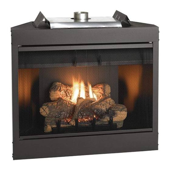
The Keystone "B" Vent Zero Clearance Gas
Fireplace
Installer: Leave these instructions with the consumer.
Consumer: Retain these instructions for future use.
WARNING: If the information in this manual is not
followed exactly, a fire or explosion may result causing
property damage, personal injury or loss of life.
- Do not store or use gasoline or other flammable
vapors and liquids in the vicinity of this or any
other appliance.
- WHAT TO DO IF YOU SMELL GAS
● Do not try to light any appliance.
● Do not touch any electrical switch; do not use any
phone in your building.
● Immediately call your gas supplier from a neighbors
phone. Follow the gas supplier's instructions.
● If you cannot reach your gas supplier, call the fire
department.
- Installation and service must be performed by
a qualified installer, service agency, or the gas
supplier.
19400-3-0406
INSTALLATION INSTRUCTIONS
OWNER'S MANUAL
GAS-FIRED
AND
B-VENT
GAS FIREPLACE
MODEL SERIES
MILLIVOLT
BVD34FP30(F,L)N-1
BVD36FP32(F,L)N-1
BVP42FP32(F,L)N-1
DIRECT IGNITION
BVD34FP50(F,L)N-1
BVD36FP52(F,L)N-1
BVP42FP52(F,L)N-1
EFFECTIVE DATE
APRIL 2006
UL FILE NO. MH45034
NOT INTENDED FOR USE AS A PRIMARY HEAT
SOURCE. This appliance is tested and approved as
either supplemental room heat or as a decorative
appliance. It should not be factored as primary heat
in residential heating calculations.
This appliance is only for use with the type of gas
indicated on the rating plate. This appliance is not
convertible for use with other gases, unless a certified
kit is used.
WARNING: If not installed, operated and maintained
in accordance with the manufacturer's instructions,
this product could expose you to substances in fuel or
from fuel combustion which can cause death or seri-
ous illness.
Page 1
Advertisement
Table of Contents
Troubleshooting

Related Manuals for White Mountain Hearth BVD34FP30


Summary of Contents for White Mountain Hearth BVD34FP30
-
Page 1: Installation Instructions
B-VENT GAS FIREPLACE MODEL SERIES MILLIVOLT BVD34FP30(F,L)N-1 BVD36FP32(F,L)N-1 BVP42FP32(F,L)N-1 DIRECT IGNITION BVD34FP50(F,L)N-1 BVD36FP52(F,L)N-1 BVP42FP52(F,L)N-1 EFFECTIVE DATE... -
Page 2: Table Of Contents
TABLE OF CONTENTS Section Page Important Safety Information ...3 Safety Information for Users of LP Gas ...4 Introduction ...5 Specifications ...6 Fireplace Dimensions ...6 Clearances ...7 Locating Fireplace ...7 Gas Supply ...8-9 Installation ...10-11 Venting ...12-13 Log Placement (BVD34 and BVD36) (5 Log Set) ...14 Log Placement (BVP42) (3 Log Set) ...15 Operating Instructions ...16-17 Standing Pilot Wiring Diagram ...18... -
Page 3: Important Safety Information
IMPORTANT SAFETY INFORMATION Before enclosing the vent pipe assembly, operate the appliance to ensure it is venting properly. • If this appliance is installed directly on carpeting, tile or other combustible material other than wood flooring the appliance shall be installed on a metal or wood panel extending the full width and depth of the appliance. -
Page 4: Safety Information For Users Of Lp Gas
SAFETY INFORMATION FOR USERS OF LP GAS Propane (LP-Gas) is a flammable gas which can cause fires and explosions. In its natural state, propane is odorless and colorless. You may not know all the following safety precautions which can protect both you and your family from an accident. -
Page 5: Introduction
• Installation of any damaged fireplace or vent system component. • Modification of the fireplace or vent system. • Installation other than as instructed by Empire Comfort Systems, Inc. • Improper positioning of the logs, glass door, optional accessories or decorative rock. -
Page 6: Specifications
Input Btu/hr Maximum KWH (Maximum) B-Vent Size NAT. (Standard) Orifice Air Shutter Opening *LP (Conversion Kit Required) Orifice Air Shutter Opening Height without standoff Width Depth Gas Inlet Shutoff Valve (Pipe) *NOTE: LP Conversion kits are included on the 120v. direct ignition model fireplaces. For millivolt models, use kit #19160 for BVD34FP Series, kit #19161 for BVD36FP Series, and kit #19162 for BVP42FP Series. -
Page 7: Clearances
Clearance to Combustibles Back 0" (0 mm) Side 0" (0 mm) Floor 0" (0 mm) Top Stand-off 0" (0 mm) Top Framing Edge 1" (25mm) Figure 2 Combustible Material No greeting cards, stockings or ornamentation of any type should be placed on or attached to the fireplace. The flow of heat can ignite combustibles. -
Page 8: Gas Supply
The gas pipeline can be brought in through the right or left side of the appliance. Consult the current National Fuel Gas Code, ANSI Z223.1 CAN/CGA-B149 (.1 or .2) installation code. Recommended Gas Pipe Diameter Pipe Length Schedule 40 Pipe (Feet) Inside Diameter Nat. -
Page 9: Gas Supply
Checking Manifold Pressures Both Propane and Natural gas valves have a built-in pressure regulator in the gas valve. Natural gas models will have a manifold pressure of approximately 3.5" w.c. (.871kPa) at the valve outlet with the inlet pressure to the valve from a minimum of 4.5" w.c. (1.120kPa) for the purpose of input adjustment to a maximum of 14.0"... -
Page 10: Installation
Framing and Finishing 1. Choose unit location. 2. Frame in fireplace with a header across the top. It is important to allow for the finished face thickness when setting the depth of the frame. See Figures 9 & 11. 3. Attach fireplace to framing using (4) adjustable nailing flanges. Preset depth to suit facing material (adjustable to 1/2", 5/8"... -
Page 11: Installation
Minimum Framing Dimensions BVD34 BVD36 "A" 35 3/4" 37 3/4" (908mm) (959mm) "B" 37 3/8" 39 3/8" (949mm) (1,000mm) "C" 14 3/8" 17 7/8" (378mm) (454mm) Note: Dimension "C" is the minimum with the fireplace face extending 1/2" in front of the framing to allow for finishing materials. Figure 11 Attention: Add 3-3/4"... -
Page 12: Venting
Vent Runs In planning the installation for the fireplace, it is necessary to install certain components before the appliance is completely positioned and installed. These include the vent system, gas piping for the appliance, Fresh Air Kit, and the electrical wiring. (The fan option is available for louvered models only. -
Page 13: Venting
Vent Size Model BVD34FP series uses a 4" B-Vent for operation. Models BVD36FP and BVP42FP series use a 6" B-Vent for operation. Never downsize venting diameters. Clearances Vent clearances are per vent manufacturer's specifications Vent Configuration Various venting configurations are shown in Figures 14 and 15 from which maximum vent runs can be determined. -
Page 14: Log Placement (Bvd34 And Bvd36) (5 Log Set)
LOG PLACEMENT (5 LOG SET) Before you begin: if you are installing logs into the BVD34 or BVD36 model, then this fireplace is supplied with a set of five ceramic fiber logs. Do not handle these logs with your bare hands! Always wear gloves to prevent skin irritation from ceramic fibers. -
Page 15: Log Placement (Bvp42) (3 Log Set)
LOG PLACEMENT (3 LOG SET) Before you begin: If you are installing logs into the BVP42 model then this fireplace is supplied with a set of three ceramic fiber logs. Do not handle these logs with your bare hands. Always wear gloves to prevent skin irritation from ceramic fibers. -
Page 16: Operating Instructions
750 Millivolt System The standing pilot (750 millivolt system) is a continuous burning pilot. The pilot remains ON even when the main burner is OFF. When you ignite the pilot, the thermopile produces millivolts (electrical current) which energizes the magnet in the gas valve. After 30 seconds to 1 minute time period you can release the gas control knob and the pilot will stay ON. -
Page 17: Operating Instructions
OPERATING INSTRUCTIONS (CONT) STANDING PILOT OPERATING INSTRUCTIONS The fireplace is equipped with a 15 foot length of wire that can be used to connect the valve to a wall switch (installer provided) or remote control receiver. See instructions packed with each of the following optional switches or controls for proper installation, operation, and maintenance. -
Page 18: Standing Pilot Wiring Diagram
STANDING PILOT WIRING DIAGRAM (OPTIONAL) REMOTE CONTROL RECEIVER (FACULTATIVE) CONTROLE E DISTANCE (OPTIONAL) THERMOSTAT (FACULATIVE) THERMOSTAT Page 18 WALL SWITCH INTERRUPTEUR MURAL LIMIT SWITCH THERMOPILE WALL SWITCH/REMOTE CONTROL RECEIVER/ THERMOSTAT CONTROLE E DISTANCE DU RECEPTEUR GAS VALVE VALVE DE GAZ Figure 23 DU RECEPTEUR GAS VALVE... -
Page 19: Standing Pilot Lighting Instructions
STANDING PILOT LIGHTING INSTRUCTIONS FOR YOUR SAFETY, READ BEFORE LIGHTING WARNING: IF YOU DO NOT FOLLOW THESE INSTRUCTIONS EXACTLY, A FIRE OR EXPLOSION MAY RESULT CAUSING PROPERTY DAMAGE, PERSONAL INJURY, OR LOSS OF LIFE A. This appliance has a pilot which must be lighted by hand. When lighting the pilot, follow these instructions exactly. -
Page 20: Standing Pilot Troubleshooting
STANDING PILOT TROUBLESHOOTING With proper installation and maintenance, your new Gas Fireplace will provide years of trouble-free service. If you do experi- ence a problem, refer to the Trouble Shooting Guide below. This guide will assist a qualified service person in the diagnosis of problems and the corrective action to be taken. -
Page 21: Standing Pilot Propane/Lp Gas Conversion
STANDING PILOT PROPANE/LP GAS CONVERSION "B-VENT" FIREPLACES Model Conversion Kit Model BVD34FP3 SERIES BVCK34P (19160) BVD36FP3 SERIES BVCK36P (19161) BVP42FP3 SERIES BVCK42P (19162) FOR CONVERSION TO LIQUEFIED PETROLEUM GAS WARNING This conversion kit is to be installed by an Empire Comfort Systems, Inc. - Page 22 If the appliance has not been installed, or a warranty card has not been returned to Empire Comfort Systems, Inc., check off type of gas converted to on card (for reference once the unit is installed).
-
Page 23: Direct Ignition Wiring Diagram
DIRECT IGNITION WIRING DIAGRAM (OPTIONAL) WALL SWITCH INTERRUPTEUR MURAL (FACULTATIVE) (OPTIONAL) REMOTE CONTROL RECEIVER 120V (FACULATIVE) CONTROLE E DISTANCE DU RECEPTEUR 120 VAC LINE BLACK NOIR 120 VAC RTN WHITE BLANC GREEN VERT JUNCTION BOX JONCTION BOÎTE Steady ON Normal operation, power ON to control 2 Flashes 3 unsuccessful ignition trials 3 Flashes... -
Page 24: Direct Ignition Lighting Instructions
DIRECT IGNITION LIGHTING INSTRUCTIONS FOR YOUR SAFETY READ BEFORE LIGHTING WARNING: IF YOU DO NOT FOLLOW THESE INSTRUCTIONS EXACTLY, A FIRE OR EXPLOSION MAY RESULT CAUSING PROPERTY DAMAGE, PERSONAL INJURY, OR LOSS OF LIFE. A. BEFORE LIGHTING smell all around the appliance area for gas. -
Page 25: Direct Ignition Troubleshooting
DIRECT IGNITION TROUBLESHOOTING With proper installation and maintenance, your new Gas Fireplace will provide years of trouble-free service. If you do experience a problem, refer to the troubleshooting guide below. This guide will assist a qualified service person in the diagnosis of problems and the corrective action to be taken. -
Page 26: Direct Ignition Propane/Lp Gas Conversion
DIRECT IGNITION PROPANE/LP GAS CONVERSION 1. Turn off the gas supply. 2. Turn off the electrical supply to the appliance if so equipped. 3. Open or remove glass doors if applicable. 4. Remove top louver and lower bottom louver. 5. Remove logs from burner assembly. VALVE CONVERSION 6. -
Page 27: Maintenance And Service
MAINTENANCE AND SERVICE PLEASE NOTE It is normal for appliances fabricated of steel to give off some expansion and/or contraction noise during the start up or cool down cycle. Similar noises are found with your furnace heat exchanger or car engine. It is not unusual for your gas fireplace to give off some odor the first time it is burned. -
Page 28: Bvd34 And Bvd36 Parts List
INDEX PART NUMBER BVD34L BVD34F BVD36L BVD36F 19506 19506 19507 17301 17301 17301 10554 10554 10554 M163 M163 M178 19387 19387 19422 19398 19398 19398 19402 19402 19434 R7052 R7052 R7052 R8137 R8137 R8148 17127 18807 17128 18808 17162 17162 17162 17163 17163... -
Page 29: Bvd34 And Bvd36 Parts View
BVD34 & BVD36 PARTS VIEW DIRECT IGNITION BURNER ASSEMBLY 19400-3-0406 MILLIVOLT BURNER ASSEMBLY 5 PIECE LOG ASSEMBLY Page 29... -
Page 30: Bvp42 Parts List
INDEX NO. PART NUMBER PART NUMBER BVP42L BVP42F 19508 19508 17247 17247 10554 10554 M178 M178 19422 19422 19398 19398 19467 19467 R7053 R7053 R8148 R8148 17187 17188 17162 17162 17163 17163 R3492 R3492 19437 19437 P200 P200 P213 P213 R5676 R5676 11499... -
Page 31: Bvp42 Parts View
DIRECT IGNITION BURNER ASSEMBLY 19400-3-0406 BVP42 PARTS VIEW MILLIVOLT BURNER ASSEMBLY 3 PIECE LOG ASSEMBLY Page 31... -
Page 32: Fbb4 Optional Variable Speed Blower Installation Instructions
FBB4 OPTIONAL VARIABLE SPEED BLOWER INSTALLATION Attention: Install blower assembly before connecting gas inlet supply line Note: Junction box on right side of fireplace must be pre-wired at time of fireplace installation for use with blower assembly. It is recommended that an ON/OFF wall switch be installed that will activate the power supply to the furnace by a qualified electrician. - Page 33 FBB4 OPTIONAL VARIABLE SPEED BLOWER INSTALLATION 19400-3-0406 FBB4 R7649 R4192 R4186 Figure 26 110 VOLT AC JUNCTION BOX Figure 27 BLOWER ASSEMBLY COMPLETE FAN CONTROL SPEED CONTROL KNOB SPEED CONTROL Page 33...
-
Page 34: Junction Box Wiring Installation Instructions
JUNCTION BOX WIRING INSTALLATION INSTRUCTIONS STANDARD MILLIVOLT VALVE MODELS CAUTION: ALL WIRING SHOULD BE DONE BY A QUALIFIED ELECTRICIAN AND SHALL BE IN COMPLIANCE WITH ALL LOCAL, CITY AND STATE BUILDING CODES. BEFORE MAKING THE ELECTRICAL CONNECTION, MAKE SURE THAT MAIN POWER SUPPLY IS DISCONNECTED. -
Page 35: Optional Accessories
The following accessory parts can be obtained from your Empire Comfort Systems dealer. If you need additional information beyond what your dealer can furnish, contact Empire Comfort Systems Inc., Nine Eighteen Freeburg Ave., Belleville, Illinois 62220-2623. Accessory Fan Kit Simulated Brick Panels... -
Page 36: Decorative Accessories
DECORATIVE ACCESSORIES Decorative Louver Mission Decorative Louver Arch Decorative Louver Leaf Decorative Frame Rectangle Decorative Door Mission Decorative Door Leaf Decorative Door Plain with hinges Rectangle Rectangle Rectangle Decorative Frame Arch with Decorative Door Leaf Arch Decorative Door Mission Arch Decorative Door Plain Arch hinges Bottom Trim Frame... -
Page 37: How To Order Repair Parts
Do not order bolts, screws, washers or nuts. They are standard hardware items and can be purchased at any local hardware store. Shipments contingent upon strikes, fires and all causes beyond our control. Empire Comfort Systems, Inc. Nine Eighteen Freeburg Ave. Belleville, Illinois 62222-2623 19400-3-0406... -
Page 38: Service Notes
SERVICE NOTES Page 38 19400-3-0406... - Page 39 SERVICE NOTES 19400-3-0406 Page 39...
- Page 40 Empire Comfort Systems, Inc. 918 Freeburg Ave. Belleville, IL 62220 PH: 618-233-7420 or 800-851-3153 FAX: 618-233-7097 or 800-443-8648 info@empirecomfort.com www.empirecomfort.com Page 40 19400-3-0406...