Table of Contents
Advertisement
D
E S I G N E D
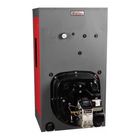
Series 24
Forced Draft Steam or Water Boilers
INSTALLATION INSTRUCTIONS
These instructions must be affixed on or adjacent to the boiler.
Models:
• 24-03
• 24-04
• 24-05
• 24-06
• 24-07
• 24-08
• 24-09
• 24-10
• 24-11
• 24-12
Tel: (215) 535-8900 • Fax: (215) 535-9736 • www.crownboiler.com
Manufacturer of Hydronic Heating Products
D
E S I G N E D
P.O. Box 14818 3633 I. Street
Philadelphia, PA 19134
L
T O
WARNING: Improper installation, adjustment, alteration,
service or maintenance can cause property damage, injury,
or loss of life. For assistance or additional information, con-
sult a qualified installer, service agency or the gas supplier.
This boiler requires a special venting system. Read these
instructions carefully before installing.
L
T O
E A D
1
E A D
Advertisement
Table of Contents

Subscribe to Our Youtube Channel
Related Manuals for Crown Boiler 24-03


Summary of Contents for Crown Boiler 24-03
-
Page 1: Installation Instructions
E S I G N E D E A D Series 24 Forced Draft Steam or Water Boilers INSTALLATION INSTRUCTIONS These instructions must be affixed on or adjacent to the boiler. Models: • 24-03 • 24-04 • 24-05 • 24-06 WARNING: Improper installation, adjustment, alteration, service or maintenance can cause property damage, injury, •... - Page 3 IMPORTANT INFORMATION - READ CAREFULLY t i l f f i t i r “ , ” “ , ” " , " DANGER CAUTION Indicates an imminently hazardous situation Indicates a potentially hazardous situation which, if not avoided, will result in death, which, if not avoided, may result in moderate serious injury or substantial property or minor injury or property damage.
- Page 4 DANGER DO NOT store or use gasoline or other flammable vapors or liquids in the vicinity of this or any other appliance. WARNING Improper installation, adjustment, alteration, service or maintenance can cause property damage, personal injury or loss of life. Failure to follow all instructions in the proper order can cause personal injury or death.
-
Page 5: Series
t t i l i t . r i l l i t i l , l i . i ( NOTICE All Series 24 cast iron boilers are designed, built, marked and tested in accordance with the ASME Boiler and Pressure Vessel Code , Section IV , Heating Boilers . An ASME Data Label is factory applied to each Series 24 jacket, which indicates the boiler Maximum Allowable Working Pressure (MAWP). -
Page 6: Table Of Contents
TABLE OF CONTENTS SECTION I - GENERAL INFORMATION Dimensional Information ............................... 8 Ratings/Data .................................. 9 Locating the Unit ................................. 10 Air Supply/Venting ............................... 11 SECTION II - CAST IRON BLOCK ASSEMBLY Assembly of Sections, Manual Draw-up ........................13 Assembly of Sections, Hydraulic Draw-up ......................... 16 Hydrostatic Test ................................ - Page 7 TABLE OF CONTENTS - Continued SECTION VI - BURNER SPECIFICATIONS Beckett Burners (Table VI) ............................57 SECTION VII - REPAIR PARTS & CARTON CONTENTS Regional Office Directory ............................58 Jacket Assembly ................................60 Bare Boiler Assembly ..............................62 Steam/Water Trim ................................. 65 RTC Related Components ............................
-
Page 9: Ratings/Data
TABLE I BOILER RATINGS/DATA ) . t ) . l ) . t " ( (1) Trim Suffix: S = Steam Boiler, W = Water Boiler Fuel Suffix: N = Natural Gas, P = LP Gas, O = Oil (2) I=B=R net ratings shown are based on piping and pick-up allowances which vary from 1.333 to 1.289 for steam and 1.15 for water. -
Page 10: Section I - General Information
SECTION I - GENERAL INFORMATION (CONTINUED) the boiler jacket of 12”. . INSPECT SHIPMENT carefully for any signs of TOP — Provide a minimum clearance from the damage. boiler jacket of 24” 1. ALL EQUIPMENT is carefully manufactured, 2. FOR MINIMUM CLEARANCES to combustible inspected and packed. -
Page 11: Air Supply/Venting
Figure 2: Boiler Foundation b. If horizontal ducts are used, each opening shall WARNING have a free area of not less than 1 sq. inch per 2,000 Btuh (70 sq. inch per gph.) (11 cm Failure to supply adequate air to the boiler per kw) of total input of all appliances in the will result in unsafe boiler operation. - Page 12 If the venting system is designed for positive or forced If the venting system is designed for negative pressure draft venting, the boiler, vent connector and stack will (natural draft), the boiler still operates with positive operate under positive pressure. Gas tight vent systems pressure in the chamber and up to the fixed damper on designed for pressure systems must be used to prevent the flue collar.
-
Page 13: Section Ii - Cast Iron Block Assembly
SECTION II - CAST IRON BLOCK ASSEMBLY ENSURE THAT THE ADHESIVE DOES CAUTION NOT COME IN CONTACT WITH THE NIPPLES OR NIPPLE PORTS. Boiler sections must be drawn-up on e. Clean nipples and nipple ports thoroughly with perfectly level surface or improper a de-greasing solvent. - Page 14 WARNING Nipples must be driven in evenly and to the proper depth to assure tight joints. Most nipple leaks are caused by tilted or cocked nipples. DO NOT use steel/iron head hammer to drive nipples without using a wood block. Nipple damage may result. g.
- Page 15 BOILER SECTION IDENTIFICATION CODE F = FRONT SECTION WITH 4” SUPPLY TAPPING C = CENTER SECTION B = BACK SECTION WITH 4” SUPPLY TAPPING CX = CENTER SECTION WITH 4” TOP SUPPLY TAPPING NOTES: FOR BOILERS LESS TANKLESS HEATER, REPLACE THE “CT” SECTIONS WITH “C” SECTIONS. Figure 8: Series 24 Section Arrangement i.
-
Page 16: Assembly Of Sections, Hydraulic Draw-Up
excessive, periodically place a heavy block of wood over each nipple port and strike as squarely as possible with several blows to relieve tension on the draw-up rods. n. CONTINUE ASSEMBLING SECTIONS IN THEIR RESPECTIVE ORDER alternating the draw-up rods from the upper to lower set of holes in draw-up lugs. - Page 17 tapped holes in the front section. Be sure to g. After all sections have been drawn up, but before screw draw-up rods into couplings far enough to removing the hydraulic rams and draw-up rods, prevent stripping threads. the 9¾” long tie rods must be installed. d.
-
Page 18: Hydrostatic Test
Figure 12: Hydraulic Draw-Up of Sections . HYDROSTATIC TEST — After the boiler sections 4. EXAMINE BOILER CAREFULLY, INSIDE AND have been assembled, it is essential that the boiler be OUTSIDE, to insure against leaks from cocked hydrostatically tested before the canopy, flue cover nipples or through concealed breakage caused in plates, jacket, or piping is installed. -
Page 19: Section Iii - Installation Instructions
SECTION III - INSTALLATION INSTRUCTIONS . INSTALL CANOPY/FLUE OUTLET ASSEMBLY, Refer to Figures 14, 15 and 16. 1. Open canopy carton. 2. Attach the two (2) canopy brackets to the front end cap of canopy with four (4) #10 x 1/2” sheet metal screws each. - Page 21 Important Product Safety Information Refractory Ceramic Fiber Product Warning: This product contains refractory ceramic fibers (RCF). RCF has been classified as a possible human carcinogen. After this product is fired, RCF may, when exposed to extremely high temperature (>1800F), change into a known human carcinogen.
-
Page 22: Flue Cover Plates
Figure 17: Left Side Canopy Intermediate Bracket Figure 18: Right Side Canopy Intermediate Bracket face outward). Secure canopy with 5/16” flat against boiler and secure with washers and nuts. washers, lock washers and brass nuts. See Tighten until insulation on cover plate provides a Figure 17. -
Page 23: Rear Observation Port Cover
6. Jacket Top Panel Attachment MOUNT REAR OBSERVATION PORT COVER Refer to Figure 16. a. On boilers with top flue outlet damper assembly, remove octagon shaped knockout. To remove 1. With the silastic sealant, secure the 3/16” diameter knockout, use a single hacksaw blade with handle rope gasket into the groove around the perimeter of or aviation snips to cut metal tabs between the rear observation port cover. -
Page 25: Burner Mounting Plate / Burner Adapter Plate
Apply four (4) small dabs of silastic on rear surface 8. Combination Label and Crown Logo Plate were of adapter plate to temporarily hold gasket in attached to jacket front panel at time of manufacture. place. Hold adapter plate in position against burner If loose or peeling, apply pressure to reset adhesive. - Page 26 Tapping Size Tapping Size Steam Boiler Steam Boiler Location Location (in) (in) Supply Float L.W.C.O. Plug (24-03 thru 24-06) Plug Supply (24-07 thru 24-12) Blow-Off Valve Operating Pressure Limit Control Hi Pressure Return Limit Control/Manual Reset Plug Gauge Glass/#67 L.W.C.O. Plug Steam Gauge (Bush to 1/4") 1-1/2...
-
Page 27: Steam Trim
Figure 25b: Steam Trim QUANTITY QUANTITY KEY DESCRIPTION BOILER MODELS DESCRIPTION BOILER MODELS CSD-1 EQUIPPED BOILERS 1/2" X 3" BR NIPPLE 1" X 12" NIPPLE PUMPED RETURN 1/2" BR UNION 4" BK PLUG 1/2" BR CLOSE NIPPLE 1-1/2" X 4 NIPPLE LWCO, #67 1-1/2"... - Page 28 STEAM BOILERS — INSTALL STEAM TRIM Items for steam trim are located in the steam trim carton (except for the separately ordered low water cutoff and tankless heater control). Figures 25a and 25b show the proper tappings for each item. f i l 1.
- Page 29 This Page Is Intentionally Left Blank.
- Page 30 Tapping Size Tapping Size Water Boiler Water Boiler Location Location (in) (in) Supply Plug Plug Probe L.W.C.O. Operating Temperature Return Limit Control Plug (24-03 thru 24-11) Hi Temperature Return (24-12) Limit Control/Manual Reset Blow-Off / Drain Valve Plug Temperature/Pressure Gauge Plug (Bush to 1/4") 1-1/2...
-
Page 31: Water Trim
Figure 26b: Water Trim QUANTITY QUANTITY DESCRIPTION BOILER MODELS DESCRIPTION BOILER MODELS 3" SQ. HD. PLUG 24-03 THRU 24-12 1-1/2" x 3/4" BLK BUSHING 24-03 THRU 24-07 3" SQ. HD. PLUG 24-12 WITH 20° DROP 1-1/2" x 1" BLK BUSHING 24-08 THRU 24-10 1"... -
Page 32: Burner Installation
BURNER INSTALLATION WATER BOILERS - INSTALL WATER TRIM Refer to burner manufacturer’s installation manual Items for water trim are located in the water trim carton for proper installation, fuel piping, wiring, burner (except for the separately ordered low water cutoff and adjustment, burner start-up and service instructions. -
Page 33: Boiler Piping - Domestic Hot Water (Dhw) Applications
A by-pass containing two closely spaced tees WARNING must be installed to de-couple the boiler loop from the primary loop (see Figure 30). Care A hot water boiler installed above radiation must be taken to avoid dead heading the level must be provided with a low water system pump. - Page 34 RTC System for a primary/secondary piping arrangement. WARNING Figure 27: Typical Crown Boiler - Primary - Secondary Loop If the boiler circulator you have selected is System (Return Temps always Greater than 135°F.) greater than 1/3 HP, an isolation relay must be added when using the RTC.
- Page 35 Recommendation 1 — Use when: • system return water is not less than 135° F for prolonged periods of time • system flow does not impact flow through the boiler Pipe Sizing and Notes F ° F ° F ° F °...
- Page 36 Recommendation 2 — Use when: • system return water is not less than 135° F for prolonged periods of time • system flow does impact flow through the boiler(ie. zoning, mixing) Pipe Sizing and Notes F ° F ° F ° F °...
- Page 37 Recommendation 3 — Use when: • system return water is less than 135° F for prolonged periods of time • system flow does impact flow through the boiler(ie. zoning, mixing) • requires addition of RTC Return Temperature Control and accessories Pipe Sizing and Notes NOTES: 1.
- Page 38 NOTICE DO NOT use the boiler circulator as an indirect domestic hot water system circulator. BOILER PIPING, DOMESTIC HOT WATER b. Shared Boiler for DHW Production – If the (DHW) APPLICATION – This section of the manual boiler(s) is(are) shared between the heating identifies the boiler piping details when domestic hot system and the production of domestic hot water is required.
-
Page 41: Tankless Heater Piping
Cut-Off Height L.W.C.O. Application "A" "B" Primary or Secondary 35-1/2" Primary (Gravity Return) 37-1/2" Primary (Pumped Return) 40" Figure 36: Mounting Elevations “B” of M&M 150, 64 and 67 “A” Float Low Water Cut-offs. cold water with the hot. In addition, savings of hot CONNECT TANKLESS HEATER PIPING as water will be achieved since the user will not waste shown in Figure 38. - Page 42 Figure 37: Minimum Piping Requirements for Series 24 Tankless Heater Manifolds - - - - - - - - - - - - - - - - - - - - - - - - - - - - - - - - - - - - - - -...
-
Page 43: Electric Wiring
shall be connected to the RTC through a junction ELECTRIC WIRING - Install all field wiring in box located above the nipple. Use grommets and accordance with the National Electric Code and Local conduit to protect the leads and connection back to Regulations. - Page 44 connectors with their corresponding conduit runs onto the RTC back panel before mounting to the bracket. The actual controller can and should be removed from the back panel during the mounting process. This will eliminate the potential for accidental damage to the controller.
-
Page 47: Section Iv - Operating Instructions
SECTION IV - OPERATING INSTRUCTIONS a. Close isolation valve in boiler supply piping. b. Isolate all circuits by closing zone valves or WARNING balancing valves. c. Attach a hose to bib cock located just below If you do not follow these instructions isolation valve in boiler supply piping. -
Page 48: Adjusting Burner
of installation. Depressing the test button will activate a test sequence and energize the red test light on the front 5. ON WATER BOILERS WITH TANKLESS of the control. Each of the controllers outputs and HEATERS, set low limit operating control dial at relays will be energized and tested. - Page 49 ASHRAE Fundamentals for the area closest to Table V: Boil Min Delay Settings the installation. This value has a default of 10°F, and is adjustable between –60ºF to 32ºF. e. WWSD – The Warm Weather Shut Down feature is used only when the outdoor reset feature is selected.
-
Page 50: Diverting Valve Actuator
both the boiler circulator and the diverting valve high fire rate. The unit will continue to fire at the high during periods of dormant activity provided power fire rate until the boiler high fire modulating limit is is supplied to the control. reached. -
Page 51: Initial Cleaning, Steam Boilers
sufficiently to permit a steady trickle of water CAUTION from the surface blowoff pipe. Continue this slow boiling and trickle of overflow for several Probe and float type low water cutoff hours until the water coming from the overflow devices require annual inspection and is clear. -
Page 52: Initial Cleaning, Water Boilers
the drain cocks at boiler and in return main and 2. Boiling Out of Boiler and System. The oil and feed water slowly up to normal level in boiler. grease which accumulate in a new hot water boiler Turn on burner and allow boiler to steam for can be washed out in the following manner. -
Page 53: Frequent Water Addition
FREQUENT WATER ADDITION OXYGEN CORROSION: l l i i l ( There are many possible causes of oxygen ½ contamination such as: ½ ½ a. Addition of excessive make-up water as a result ½ of system leaks. ½ b. Absorption through open tanks and fittings. c. -
Page 54: Section V - Service Instructions
SECTION V - SERVICE INSTRUCTIONS DANGER This boiler uses flammable gas, high voltage electricity, moving parts, and very hot water under high pressure. Assure that all gas and electric power supplies are off and that the water temperature is cool before attempting any disassembly or service. More than one gas shut-off valve and electrical disconnect switch are used on the boiler. -
Page 55: Maintenance Of Low Water Cutoff Devices
b. Using wire or fibre bristle brush clean crown of DANGER boiler and inside of water legs. c. Inspect target wall (903A only) for damage or Assure that the boiler is at z ero pressure deterioration. If target wall is damaged, replace. before removing the LWCO probe. -
Page 56: Checking Burner & Controls
2. FLOAT TYPE LOW WATER CUTOFF 3. If much water is added to system, it is advisable to During the heating season, if an external low water heat system to a high temperature and vent again. This will make less venting necessary during the cutoff is on the boiler, the blow off valve should winter. - Page 57 SECTION VI - BURNER SPECIFICATIONS Table VI: Beckett Burner Specifications OIL BURNERS ° 5 ° 5 ° 5 ° 0 ° 5 ° 5 ° 5 ° 5 ° 5 ° 5 ° 5 ° 5 GAS BURNERS (Natural Gas) Damper Settings Manifold Pressure ("WC) Minimum Inlet Pressure "WC...
- Page 58 SECTION VII - REPAIR PARTS & CARTON CONTENTS The following parts may be obtained from any Crown distributor. To find the closest Crown distributor, consult the area Crown representative or the factory at: Crown Boiler Co. Customer Service P.O. Box 14818 Philadelphia, PA 19134 www.crownboiler.com...
- Page 59 CARTON BOILER CARTON BOILER CARTON JACKET CARTON CANOPY CARTON BUNRER SPECIFICATIONS BURNER SECTION CARTON CROWN APPROPRIATE FIGURE PLATE ADAPTER BURNER 330404 330408 CARTON WALL TARGET 330025 CARTON TRIM STEAM 331220 CARTON TRIM WATER 331210 CARTON OBS. FLAME 330050 330136 330135 330134 330133 331202...
- Page 61 JACKET CARTON CROWN CARTON PART # QUANTITY CROWN DESCRIPTION PART # FRONT JACKET PANEL 330310 REAR JACKET PANEL 330320 UPPER TIE BAR ASSY, 3 SEC. 330333 UPPER TIE BAR ASSY, 4 SEC. 330334 UPPER TIE BAR ASSY, 5 SEC. 330335 UPPER TIE BAR ASSY, 6 SEC.
- Page 63 SECTION JOINER CARTON ASSY CROWN QUANTITY DESCRIPTION PART # "F" "G" "H" 7" PUSHNIPPLE 310005 3" PUSHNIPPLE 310006 5/8 X 9 3/4 TIE ROD 900310 5/8 HEAVY HEX NUT (GRADE 9) 900307 5/8 HI-STRENGTH FLAT WASHER 900308 LOCTITE # 592, 50 ml TUBE 900350 GASKET ROPE, 3/8 DIA x 96"...
- Page 64 REAR FLUE OUTLET CARTON CROWN QUANTITY KEY DESCRIPTION PART # 7" REAR OUTLET DAMPER ASSY 333007 8" REAR OUTLET DAMPER ASSY 333008 10" REAR OUTLET DAMPER ASSY 333010 12" REAR OUTLET DAMPER ASSY 333012 TOP OUTLET COVER, 7"& 8" OPENING 333017 TOP OUTLET COVER, 10"...
- Page 65 STANDARD STEAM TRIM CARTON ASSY. CROWN DESCRIPTION QUANTITY PART # LWCO, #67 400682 GLASS SET (11.25" CTR TO CTR) 950082 L404F1367 3503800 1/2 X 3 BR NIPPLES 95-116 1/2" BR. UNION 95-150 1/2 X CL BRASS NIPPLE 95-147 3/4 BLACK EXTENSION 95-090 3/4 X 1/4 BRASS BUSHING 950016...
- Page 66 V Return Temperature Control (RTC) Packages (CONSULT APPENDIX B1, B2, B3 & B4 IN THE I/O MANUAL FOR VALVE SELECTION) DESCRIPTION CROWN PART # 330800 330810 330850 330851 330852 330853 330854 330855 330856 1" VALVE WITH OUTDOOR RESET 1" VALVE W/O OUTDOOR RESET 1 1/4"...
- Page 67 Tankless Coil Components CROWN DESCRIPTION QUANTITY PART # S24 TANKLESS HEATER CARTON 330020 INCLUDES: 12A S-24 TANKLESS HEATER 11 GASKET 330021 3/8 X 7/8 "ASME BOLTS" 3/8 WASHER CSD-1 Packages A. WATER CROWN DESCRIPTION QUANTITY PART # HYDROLEVEL 550 LWCO 450560 L4006E1109 35-3100...
- Page 68 BUSHING 1-1/4 1-1/2 95-047 BUSHING 1-1/2 950185 BUSHING 1-1/2 95-096 13-214 CONBRACO 950525 VALVE, SAFETY 13-213 CONBRACO 950520 VALVE, SAFETY 13-202 CONBRACO 950515 VALVE, SAFETY 13-211 CONBRACO 950510 VALVE, SAFETY PLUG BLACK 4" 950274 BUSHING 950192 BUSHING 950098 INSTRUCTIONS NOZZLE 980419 NOZZLE 8.00/45P...
- Page 69 NIPPLE 1-1/4 95-031 ELBOW 1-1/4 95-058 NIPPLE 1-1/4 95-033 BUSHING 1-1/4 1-1/2 95-047 NIPPLE 950110 ELBOW 950190 NIPPLE 950114 BUSHING 1-1/2 950185 NIPPLE 95-105 ELBOW 95-057 NIPPLE 95-027 BUSHING 1-1/2 95-096 10-616-05 CONBRACO 950500 VALVE, RELIEF 10-615-05 CONBRACO 95-134 VALVE, RELIEF 10-614-05 CONBRACO...
- Page 70 SECTION VIII - APPENDIX...
- Page 84 APPENDIX B1 - Series 24 Boiler Circulator and Diverting Valve Selection Chart, 20°F & 40°F DT, TACO F ° " " 0 " 5 " 0 " 5 " 7 " 0 " 2 " 5 " 5 " 5 "...
- Page 85 APPENDIX B2 - Series 24 Boiler Circulator and Diverting Valve Selection Chart, 20°F & 40°F ∆T, Grundfos F ° " " 0 " 5 " 0 " 5 " 0 " 2 " 5 " 5 " 5 " 5 "...
- Page 86 APPENDIX B3 - Series 24 Boiler Circulator and Diverting Valve Selection Chart, 20°F & 40°F ∆T, Bell and Gossett F ° " " 0 " 5 " 5 " 0 " 5 " 2 " 0 " 2 " 2 "...
- Page 87 APPENDIX B4 - Series 24 Boiler Circulator and Diverting Valve Selection Chart, 20°F & 40°F ∆T, Armstrong F ° " " 0 " 5 l l u - - - " 0 " 5 " 0 " 2 " 5 "...
- Page 88 APPENDIX C – VALVE AND ACTUATOR MOUNTING INSTRUCTIONS Application For use with ESBE ½” to 6” 3-Way and 4-Way rotary valves for mixing and diverting applications. Use with 24Vac 3-point “floating” signal controller. Mounting the Motor 1. Place drive sleeve onto shaft and secure with bolt . Check that the valve is in mid-position (sleeve pointer set to position 5 on scale plate). 2.
-
Page 89: Service Record
SERVICE RECORD DATE SERVICE PERFORMED... -
Page 90: P.o. Box 14818 3633 I. Street Philadelphia, Pa
Manufacturer of Hydronic Heating Products E S I G N E D E A D P.O. Box 14818 3633 I. Street Philadelphia, PA 19134 Tel: (215) 535-8900 • Fax: (215) 535-9736 • www.crownboiler.com PN: 980417 S24 - 12/05...
Need help?
Do you have a question about the 24-03 and is the answer not in the manual?
Questions and answers