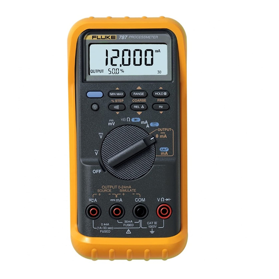
Fluke ProcessMeter 787 User Manual
Processmeter
Hide thumbs
Also See for ProcessMeter 787:
- User manual (52 pages) ,
- Calibration manual (40 pages) ,
- Safety information (4 pages)

Related Manuals for Fluke ProcessMeter 787


Summary of Contents for Fluke ProcessMeter 787
- Page 1 ® ProcessMeter Users Manual April 1997, Rev.3, 12/01 © 1997, 1898, 2000, 2001 Fluke Corporation, All rights reserved. Printed in U.S.A. All product names are trademarks of their respective companies.
- Page 2 LIMITED WARRANTY & LIMITATION OF LIABILITY This Fluke product will be free from defects in material and workmanship for three years from the date of purchase. This warranty does not cover disposable batteries or damage from accident, neglect, misuse or abnormal conditions of operation or handling.
-
Page 3: Table Of Contents
Table of Contents Title Page Introduction........................1 Contacting Fluke ......................1 Safety Information ......................2 How to Get Started......................5 Getting Acquainted with the Meter ................6 Measuring Electrical Parameters................... 17 Input Impedance....................... 17 Ranges ........................17 Measuring a Composite Signal................. 17 Testing Diodes...................... - Page 4 Users Manual Simulate Mode ......................22 Changing the Current Span ..................22 Producing a Steady mA Output................. 24 Manually Stepping the mA Output ................25 Auto Ramping the mA Output ................... 26 Power-Up Options......................27 Battery Life........................28 Using the Holster and Flex-Stand .................. 28 Maintenance ........................
-
Page 5: Introduction
To order accessories, receive operating assistance, or get Your Fluke 787 ProcessMeter (referred to as “the the location of the nearest Fluke distributor or Service meter”) is a handheld, battery-operated tool for measuring Center, call: electrical parameters and supplying steady or ramping USA : 1-888-99-FLUKE (1-888-993-5853) current to test process instruments. -
Page 6: Safety Information
The Netherlands manual, otherwise the protection provided by the meter may be impaired. Or visit us on the World Wide Web: www.fluke.com A Warning identifies conditions and actions that pose hazard(s) to the user; a Caution identifies conditions and actions that may damage the meter or the equipment under test. - Page 7 ProcessMeter Safety Information Make sure the battery door is closed and Caution latched before you operate the meter. To avoid possible damage to meter or to equipment under test: Remove test leads from the meter before you open the battery door. Disconnect the power and discharge all high- voltage capacitors before testing resistance Inspect the test leads for damaged...
- Page 8 Users Manual Table 1. International Symbols Symbol Meaning Symbol Meaning Alternating current Earth ground Direct current Fuse Alternating or direct current Conforms to European Union directives Refer to the manual for information about Conforms to relevant Canadian this feature. Standards Association directives Battery Double insulated Meets Underwriters’...
-
Page 9: How To Get Started
ProcessMeter How to Get Started How to Get Started If you are familiar with the Fluke 80 Series DMM, read Display “Using the Current Output Functions,” review the tables PROCESSMETER and figures in “Getting Acquainted with the Meter,” and begin using your meter. -
Page 10: Getting Acquainted With The Meter
Users Manual Figure and Table 4 describe the output functions you Getting Acquainted with the Meter get with the last two rotary switch positions. To become familiar with the features and functions of the Figure and Table 5 describe the functions of the meter, study the following figures and tables. - Page 11 ProcessMeter Getting Acquainted with the Meter Table 2. Input/Output Jacks Item Jack Measurement Functions Source Current Simulate Transmitter Function Function Input for current to 440 mA Output for dc current to 24 mA. continuous. (1A for up to 30 seconds.) Fused with a 440 mA fuse.
- Page 12 Users Manual OUTPUT ee002f.eps Figure 3. Rotary Switch Positions for Measurements...
- Page 13 ProcessMeter Getting Acquainted with the Meter Table 3. Rotary Switch Positions for Measurements Position Function(s) Pushbutton Actions Meter off Default: Selects a MIN, MAX, or AVG action (see pg. 18) measure ac V Selects a fixed range (hold 1 second for auto range) Toggles TouchHold Frequency counter Toggles relative reading (sets a relative zero point)
- Page 14 Users Manual OUTPUT ee008.eps Figure 4. Rotary Switch Positions for mA Output...
- Page 15 ProcessMeter Getting Acquainted with the Meter Table 4. Rotary Switch Positions for mA Output Position Default Function Pushbutton Actions Test leads in % STEP : Adjusts output up or down to the next 25% step OUTPUT SOURCE: COARSE : Adjusts output up or down 0.1 mA Source 0% mA FINE : Adjusts output up or down 0.001 mA...
- Page 16 Users Manual MIN MAX RANGE HOLD % STEP COARSE FINE ee003f.eps Figure 5. Pushbuttons Table 5. Pushbuttons Pushbutton Function(s) Toggles the backlight Rotary switch in mA A position and test lead plugged into A jack: Toggles between ac and dc ampere measure (BLUE) Rotary switch in position: Selects diode test function (...
- Page 17 ProcessMeter Getting Acquainted with the Meter Table 5. Pushbuttons (cont.) Pushbutton Function(s) Measuring: Selects a MIN, MAX, or AVG action (see pg. 18) mA Output: Adjusts mA output up to the next higher 25% step % STEP Measuring: Selects a fixed range (hold for 1 second for auto range) mA Output: Adjusts output up 0.1 mA COARSE Measuring: Toggles TouchHold, or in MIN MAX recording, suspends recording...
- Page 18 Users Manual ee004f.eps Figure 6. Elements of the Display...
- Page 19 ProcessMeter Getting Acquainted with the Meter Table 6. Display Element Meaning Shows the mA measured value or output level in %, in a 0-20 mA or 4-20 mA scale Percentage display (change scales with power-up option) Lights when mA output (source or simulate) is active OUTPUT Lights in diode test function Lights in continuity function...
- Page 20 Users Manual Table 6. Display (cont.) Meaning Element Show the input or output units and multipliers associated with the numerals mA, DC, mV, AC, M or k , kHz Range status indicators: Auto Auto means autoranging is on. 400100030 The number plus the unit and multiplier indicate the active range. One of these lights in mA ramping or step output (rotary switch position mA means slow continuous 0% - 100% - 0% ramping.
-
Page 21: Measuring Electrical Parameters
ProcessMeter Measuring Electrical Parameters The meter normally automatically selects the lowest Measuring Electrical Parameters range that will measure the applied input signal (Auto The proper sequence for taking measurements is as showing on the display). Press if you want to lock follows: the range. -
Page 22: Testing Diodes
Users Manual Testing Diodes Displaying Minimum, Maximum, and Average To test a single diode: MIN MAX recording stores the lowest and highest measurements, and maintains the average of all Insert the red test lead into the jack and measurements. black test lead into the COM jack. Press to turn on MIN MAX recording. -
Page 23: Using Touchhold
ProcessMeter Measuring Electrical Parameters Using TouchHold Compensating for Test Lead Resistance Use the relative reading feature (Q on the display) to set Note the present measurement as a relative zero. A common You must have MIN MAX recording off to use use for this is to compensate for test lead resistance TouchHold. -
Page 24: Using The Current Output Functions
Users Manual current into a passive circuit such as a current loop with Using the Current Output Functions no loop supply. Source mode depletes the battery faster than simulate mode, so use simulate mode whenever The meter provides steady, stepped, and ramped current possible. - Page 25 ProcessMeter Using the Current Output Functions PROCESSMETER MIN MAX RANGE HOLD % STEP COARSE FINE OUTPUT OUTPUT 0-24mA SOURCE SIMULATE 30mA 0.44A FUSED 1000V (1A /30 sec) FUSED ee010f.eps Figure 7. Sourcing Current...
-
Page 26: Simulate Mode
Users Manual Simulate Mode Changing the Current Span Simulate mode is so named because the meter simulates The meter’s current output span has two settings (with a current loop transmitter. Use simulate mode when an overrange to 24 mA): external dc voltage of 24 to 30V is in series with the 4 mA = 0%, 20 mA = 100% (factory default) current loop under test. - Page 27 ProcessMeter Using the Current Output Functions dc V Power Supply PROCESSMETER +24V MIN MAX RANGE HOLD % STEP COARSE FINE OUTPUT OUTPUT 0-24mA SOURCE SIMULATE 30mA 0.44A FUSED 1000V (1A /30 sec) FUSED ee011f.eps Figure 8. Simulating a Transmitter...
-
Page 28: Producing A Steady Ma Output
Users Manual Producing a Steady mA Output Table 8. mA Output Adjust Pushbuttons When the rotary switch is in the OUTPUT mA position, Pushbutton Adjustment and the OUTPUT jacks are connected to an appropriate load, the meter produces a steady mA dc output. The Adjusts up 0.1 mA meter begins sourcing or simulating 0%. -
Page 29: Manually Stepping The Ma Output
ProcessMeter Using the Current Output Functions Manually Stepping the mA Output Table 9. mA Stepping Pushbuttons When the rotary switch is in the OUTPUT mA position, Pushbutton Adjustment and the OUTPUT jacks are connected to an appropriate load, the meter produces a steady mA dc output. The Adjusts up to the next higher meter begins sourcing or simulating 0%. -
Page 30: Auto Ramping The Ma Output
Users Manual When the rotary switch is in the OUTPUT mA Table 10. mA Step Values position, the meter produces a continuously Step Value (for each span setting) repeating 0% - 100% - 0% ramp in your choice of three ramp waveforms: 4 to 20 mA 0 to 20 mA... -
Page 31: Power-Up Options
ProcessMeter Power-Up Options Only the setting for current span is retained when the Power-Up Options power is turned off. The others have to be repeated for To select a power-up option, hold down the pushbutton each operating session. shown in Table 11 while turning the rotary switch from OFF to any on position. -
Page 32: Battery Life
Measuring any parameter or simulating current Calibration Sourcing 12 mA into 500 Calibrate your meter once a year to ensure that it performs according to its specifications. Contact a Fluke Service Center for instructions. - Page 33 ProcessMeter Maintenance Holster with Flex-Stand bent Holster with probe in clip Holster with Flex-Stand extended Meter in holster face down for protection Holster with Flex-Stand Holster with Flex-Stand (Store Quick Reference Card under meter) looped over wall looped over belt ee009f.eps Figure 9.
-
Page 34: Replacing The Battery
Users Manual Replacing the Battery ! Warning To avoid electrical shock, remove test leads from the meter before you open the battery door. Close and latch the battery door before you use the meter. Remove test leads from the meter before you open the battery door. -
Page 35: Replacing A Fuse
Plug the black test lead into COM, and the red test lead into cA. Replace the blown fuse with the exact type specified: 440 mA 1000V fast-blow fuse, Fluke PN 943121. Using an ohmmeter, check the resistance between Both fuses are the same type. -
Page 36: If The Meter Does Not Work
Review this manual to make sure you are using the correct jacks and rotary switch position. If the meter still does not work, contact a Fluke Service Center. If the meter is under warranty, it will be repaired or replaced (at Fluke’s option) and returned at no charge. -
Page 37: Replacement Parts And Accessories
Replacement Parts and Accessories Figure 12 and listed in Table 13. Many more DMM ! Warning accessories are available from Fluke. For a catalog, contact your nearest Fluke distributor. To avoid personal injury or damage to the meter, use only the specified replacement... - Page 38 Users Manual Table 13. Replacement Parts Item Description Fluke PN or Model no. Quantity 9V battery, ANSI/NEDA 1604A or IEC 6LR61 614487 CG81Y Holster, Yellow CG81G F1, 2 Fuse, 440 mA, 1000V fast-blow 943121 MP85 Case top 619962 MP86 Case bottom...
- Page 39 ProcessMeter Replacement Parts and Accessories TL75 MP85 Test Lead Set TL20 (Option) Industrial Test Lead Set AC70A Alligator Clips Holster CG81Y Product MP86 Overview Manual H2, 3, 4 MP89, 90 CD-ROM (Users Manual) MP92 H5, 6 ee015c.eps Figure 12. Replacement Parts...
-
Page 40: Specifications
Users Manual The standard specification interval is 1 year. Specifications Note All specifications apply from +18 C to +28 C unless stated otherwise. “Counts” means number of increments or decrements of the least significant digit. All specifications assume a 5 minute warmup period. DC Volts Measurement Range (V dc) Resolution... - Page 41 ProcessMeter Specifications DC Millivolts Measurement Range (mV dc) Resolution Accuracy (% of Reading + Counts) 400.0 0. 1 mV 0.1% + 1 AC Volts Measurement Range (ac) Resolution Accuracy, (% of Reading + Counts) 50 Hz to 60 Hz 45 Hz to 200 Hz 200 Hz to 500 Hz 400.0 mV 0.1 mV...
- Page 42 Users Manual AC Current Measurement Range Resolution Accuracy, (% of Reading + Counts) Typical Burden 45 Hz to 2 kHz Voltage 1.000A (Note) 0.001A 1% + 2 1.5V/A Note: 440 mA continuous, 1A 30 seconds maximum Specifications are valid from 5% to 100% of amplitude range. AC conversion: true rms Maximum crest factor: 3 For non-sinusoidal waveforms, add (2% reading + 2% f.s.) typical...
- Page 43 ProcessMeter Specifications Ohms Measurement Range Resolution Measurement Current Accuracy, (% of Reading + Counts) 400.0 0. 1 220 A 0.2% + 2 4.000 k 0.001 k 59 A 0.2% + 1 40.00 k 0.01 k 5.9 A 0.2% + 1 400.0 k 0.1 k 590 nA...
- Page 44 Users Manual Frequency Counter Accuracy Range Resolution Accuracy, (% of Reading + Counts) 199.99 Hz 0.01 Hz 0.005% + 1 1999.9 Hz 0.1 Hz 0.005% + 1 19.999 kHz 0.001 kHz 0.005% + 1 Display updates 3 times/second at >10 Hz Frequency Counter Sensitivity Input Range Minimum Sensitivity (rms Sinewave)
- Page 45 ProcessMeter Specifications Compliance voltage: 21V for 24V supply Diode Test and Continuity Test Diode test indication: display voltage drop: 0.2 mA Burden voltage: <3V nominal test current at 0.6V: 2.4V full scale, accuracy General Specifications (2% + 1 count) Maximum voltage applied between any jack and earth Continuity test indication: continuous audible tone for ground: 1000V test resistance <100...
- Page 46 Users Manual Vibration: Random 2g, 5 to 500 Hz Shock: 1 meter drop test Water and dust protection: Complies with IEC529 IP52 (normal operating vacuum used for dust test) Safety: Complies with IEC1010-1, ANSI/ISA S82.01- 1994 and CAN/CSA C22.2 No. 1010.1-92 Overvoltage Category III.
-
Page 47: Index
Index Current output Compliance, 24 —A— Load impedance, 24 Ramping, auto, 26 Auto Simulating a transmitter, 22 Ramping, 17, 26 Ranging, 17 Sourcing, 20 Span (4-20 mA or 0-20 mA), 22 Stepping, 17 Steady, 24 Stepping, auto, 26 —B— Stepping, manually, 25 With external loop supply, 22 Battery Replacement, 30... - Page 48 Users Manual —F— M— mA output. See Current output Flex-Stand, 28 Freezing a reading (TouchHold), 19 Mailing address for Fluke, 2 Fuse, checking and replacing, 31 Maintenance, 28 Malfunction, 32 Measuring, 17 —H— MIN MAX recording, 18 Holster, 28 —O—...
- Page 49 Rotary switch positions, 9, 11 Telephone numbers, 1 —S— TouchHold, 19 Safety information, 2 —W— Screen, 15 Service and sales, 1 Warranty. See back of Title Page Settings, 27 Service, 32 Simulating. See Current output WWW address for Fluke, 2...
- Page 50 Users Manual...