
Related Manuals for 3Com 3CRDSF9PWR-US - OfficeConnect Managed Fast Ethernet PoE Switch


Summary of Contents for 3Com 3CRDSF9PWR-US - OfficeConnect Managed Fast Ethernet PoE Switch
-
Page 1: User Guide
® 3Com OfficeConnect Managed PoE Switch User Guide 3CRDSF9PWR www.3Com.com Part Number 10016863 Rev. BB Published August 2009... - Page 2 All other company and product names may be trademarks of the respective companies with which they are associated. ENVIRONMENTAL STATEMENT It is the policy of 3Com Corporation to be environmentally friendly in all operations. To uphold our policy, we are committed to: Establishing environmental performance standards that comply with national legislation and regulations.
-
Page 3: User Guide Overview
OfficeConnect Managed Fast Ethernet PoE Switch and how it can be used in your network. It covers summaries of hardware and software features. Using the 3Com Web Interface — Provides information for using ■ the Web interface including adding, editing, and deleting device configuration information. - Page 4 BOUT UIDE Aggregating Ports — Provides information for configuring Link ■ Aggregation which optimizes port usage by linking a group of ports together to form a single LAG. Configuring VLANs — Provides information for configuring VLANs. ■ VLANs are logical subgroups with a Local Area Network (LAN) which combine user stations and network devices into a single virtual LAN segment, regardless of the physical LAN segment to which they are attached.
-
Page 5: Intended Audience
Most user guides and release notes are available in Adobe Acrobat Reader Portable Document Format (PDF) or HTML on the 3Com Web site: http://www.3Com.com ■ Conventions Table 1 lists conventions that are used throughout this guide. - Page 6 BOUT UIDE...
-
Page 7: Table Of Contents
ONTENTS BOUT UIDE User Guide Overview ..................3 Intended Audience ..................5 Conventions....................5 Related Documentation................5 ETTING TARTED About the OfficeConnect Managed Fast Ethernet PoE Switch ....16 Summary of Hardware Features ............16 Front Panel Detail ..................17 LED Status Indicators ................18 System Specifications ................19 Approved SFP Transceivers .............. - Page 8 Starting the 3Com Web Interface............. 36 Multi-Session Web Connections ............. 36 Accessing the 3Com Web Interface ..........37 Understanding the 3Com Web Interface ..........38 Device Representation ..............40 Using the 3Com Web Interface Management Buttons ....40 Using Screen and Table Options ............... 41 Saving the Configuration .................
- Page 9 Configuring Port Settings ............... 69 Viewing User Listing ............... 70 Creating User Entries ..............71 Modifying User Entries ..............72 Removing User Entries ..............73 Encrypting Connection to the Web Interface (HTTPS)........74 Configuring HTTPS ................. 75 Displaying the Web Server Certificate ..........
- Page 10 Viewing Port Details ..............118 GGREGATING ORTS Viewing Link Aggregation ............122 Configuring Link Aggregation ............123 Modifying Link Aggregation ............125 Removing Link Aggregation ............127 Viewing LACP ................128 Modifying LACP ................129 VLAN ONFIGURING Viewing VLAN Details ..............
- Page 11 Defining Port Settings for Spanning Tree ........160 SNMP ONFIGURING Setting SNMP Agent Status ............164 Defining SNMP Communities and Traps ........165 Removing SNMP Communities or Traps ........167 ONFIGURING UALITY OF ERVICE Viewing CoS Settings ..............170 Defining CoS ................
- Page 12 Pinging Another Device................223 ETWORK ANAGEMENT 3Com Network Supervisor ..............225 3Com Network Director................. 226 3Com Network Access Manager ............226 3Com Enterprise Management Suite............227 Integration Kit with HP OpenView Network Node Manager ....227 EVICE PECIFICATIONS AND EATURES Related Standards ..................
- Page 13 ROUBLESHOOTING Problem Management ................239 Troubleshooting Solutions ..............239 Fail Safe Commands ................241 LOSSARY ......................243 BTAINING UPPORT FOR RODUCTS Register Your Product to Gain Service Benefits ........249 TTroubleshoot Online ................249 Purchase Extended Warranty and Professional Services ......250 Access Software Downloads ..............250 Telephone Technical Support and Repair ..........250 Contact Us .....................251 EGULATORY OTICES...
-
Page 15: Getting Started
ETTING TARTED This chapter contains introductory information about the 3Com® OfficeConnect Managed Fast Ethernet PoE Switch and how it can be used in your network. It covers summaries of hardware and software features and also the following topics: About the OfficeConnect Managed Fast Ethernet PoE Switch ■... -
Page 16: About The Officeconnect Managed Fast Ethernet Poe Switch
1: G HAPTER ETTING TARTED About the The OfficeConnect Managed Fast Ethernet PoE Switch is a switching OfficeConnect product that delivers flexible three-speed performance (10/100/1000), Managed Fast Power over Ethernet (PoE and PoE Plus) and advanced voice-optimized Ethernet PoE features such as auto-QoS and auto-voice VLAN. This makes the switch Switch ideal for small enterprises seeking to build a secure converged network. -
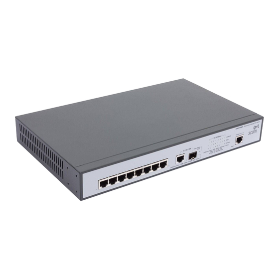
Page 17: Front Panel Detail
Front Panel Detail Table 1 Hardware Features (continued) Feature OfficeConnect Managed Fast Ethernet PoE Switch Traffic Prioritization Supported (using the IEEE Std 802.ID, 1998 Edition): Four traffic queues per port Power over Ethernet and Supported on ports 1-8 Power over Ethernet Plus Fast Ethernet Ports Auto-negotiating 10/100BASE-TX ports Gigabit Ethernet Ports... -
Page 18: Led Status Indicators
1: G HAPTER ETTING TARTED LED Status The OfficeConnect Managed Fast Ethernet PoE switch provides LED Indicators indicators on the front panel for your convenience to monitor the switch. Table 2 describes the meanings of the LEDs. Table 2 Description on the LEDs of the OfficeConnect Managed Fast Ethernet PoE Switch Label Status Description... -
Page 19: System Specifications
The following list of approved SFP transceivers is correct at the time of Transceivers publication. 3CSFP91 SFP (1000BASE-SX) ■ 3CSFP92 SFP (1000BASE-LX) ■ To access the latest list of approved SFP transceivers for the switch on the 3Com Corporation World Wide Web site, enter this URL into your Internet browser: http://www.3com.com... -
Page 20: Installing The Switch
AVERTISSEMENT: Consignes de securite. Avant d'installer ou d'enlever tout composant de switch ou d'entamer une procedure de maintenance, lisez les informations relatives a la securite qui se trouvent dans 3Com Switch Family Safety and Regulatory Information. VORSICHT: Sicherheitsinformationen. Bevor Sie Komponenten aus... -
Page 21: Setting Up For Management
You can use the Command Line Interface through the Console port for complete access to all operations of the switch including setting and viewing the IP address, configuring user accounts, upgrading switch firmware, and more. Refer to the 3Com CLI Reference Guide. -
Page 22: Web Interface Management
1: G HAPTER ETTING TARTED Web Interface Each switch has an internal set of web pages that allow you to manage Management the switch using a Web browser remotely over an IP network (see Figure 2). Figure 2 Web Interface Management over the Network Refer to “Setting Up Web Interface Management”... -
Page 23: Snmp Management
You can manage a switch using any network management workstation running the Simple Network Management Protocol (SNMP) as shown in Figure 5. For example, you can use the 3Com Network Director software, available from the 3Com web site. Figure 5 SNMP Management over the Network Refer to “Setting Up SNMP Management V1 or V2”... - Page 24 1: G HAPTER ETTING TARTED Figure 6 Initial Switch Setup and Management Flow Diagram Power Up the Switch. Is a DHCP server present? IP Information is automatically The switch uses its default IP configured using DHCP information See page 25 See page 25 Do you want to manually configure the IP information?
-
Page 25: Ip Configuration
Switch Setup Overview IP Configuration The switch’s IP configuration is determined automatically using DHCP, or manually using values you assign. Automatic IP Configuration using DHCP By default the switch tries to configure its IP Information without requesting user intervention. It tries to obtain an IP address from a DHCP server on the network. -
Page 26: Using The Command Line Interface (Cli)
IP address, or to view the IP address that was assigned automatically (for Interface (CLI) example, by a DHCP server). For more information about the CLI, refer to the 3Com CLI Reference Guide. Connecting to the This section describes how to connect to your switch through the Console Port Console port. -
Page 27: Manually Set The Ip Address Using The Console Port
Using the Command Line Interface (CLI) Connecting the Workstation to the Switch 1 Connect the workstation to the console port using the console cable as shown in Figure 7. Figure 7 Connecting a Workstation to the switch using the Console Port To connect the cable: a Attach the cable’s RJ-45 connector to the Console port of the switch. -
Page 28: Viewing Ip Information Using The Console Port
1: G HAPTER ETTING TARTED 1 Connect to the switch Console port as described in “Connecting to the Console Port” page 26. 2 The command line interface login sequence begins as soon as the switch detects a connection to its console port. When the process completes, the Login prompt displays. - Page 29 See “Methods of Managing a Switch” on page 21. For more information about the CLI, refer to the 3Com CLI Reference Guide. If you do not intend to use the command line interface using the console port to manage the switch, you can log out, disconnect the serial cable and close the terminal emulator software.
-
Page 30: Setting Up Web Interface Management
1: G HAPTER ETTING TARTED Setting Up Web This section describes how you can set up web interface management Interface over the network. Management Prerequisites Ensure you have already set up the switch with IP information as ■ described in “Methods of Managing a Switch” on page 21. Ensure that the switch is connected to the network using a Category 5 ■... -
Page 31: Web Management Over The Network
Setting Up Command Line Interface Management Web Management To manage a switch using the web interface over an IP network: Over the Network 1 Be sure that you know your switch’s IP address. See “IP Configuration” on page 25, and “Viewing IP Information using the Console Port” on page 28. -
Page 32: Cli Management Over The Network
Network Management Protocol (SNMP) to manage the switch. 3Com offers a range of network management applications to address networks of all sizes and complexity. See “3Com Network Management” on page 225. Be sure the management workstation is connected to the switch using a port in VLAN 1 (the Default VLAN). -
Page 33: Default Users And Passwords
Default Users and Passwords To display and configure SNMP management parameters, refer to “Configuring SNMP” on page 163. Default Users and If you intend to manage the switch or to change the default passwords, Passwords you must log in with a valid user name and password. The switch has two default user names. - Page 34 1: G HAPTER ETTING TARTED where aaa.aaa.aaa.aaa is the IP address of the TFTP server, and rrr is the source runtime filename. 2 When downloading a new runtime file, it will automatically overwrite the previous version. To set the switch to boot from the new runtime file you have downloaded, enter the reload command as shown below: Console(config)# reload...
-
Page 35: Using The 3C Om Web Interface
SING THE NTERFACE This section provides an introduction to the user interface, and includes the following topics: Starting the 3Com Web Interface ■ Understanding the 3Com Web Interface ■ Using Screen and Table Options ■ Saving the Configuration ■ Resetting the Device ■... -
Page 36: Starting The 3Com Web Interface
Configuring System Access. Login information is always handled in the local database. A unique password is required of each user. Two access levels exist on the 3Com Web Interface: Management access level — Provides the user with read/write ■... -
Page 37: Accessing The 3Com Web Interface
Starting the 3Com Web Interface Accessing the 3Com This section contains information on starting the 3Com Web interface. Web Interface To access the 3Com user interface: 1 Open an Internet browser. 2 Enter the device IP address in the address bar and press Enter. The Enter... -
Page 38: Understanding The 3Com Web Interface
Figure 9 3Com Web Interface Home Page Port Indicators Tree View Tab View Understanding the The 3Com Web Interface Home Page contains the following views: 3Com Web Tree View — Provides easy navigation through the configurable ■ Interface device features. The main branches expand to display the sub-features. - Page 39 Understanding the 3Com Web Interface Figure 10 Web Interface Components Tab View Tree View Web Interface Information The following table lists the user interface components: Table 6: Interface Components View D escr ip tio n Tree View Tree View provides easy navigation through the configurable device features.
-
Page 40: Device Representation
■ instructions for adding, modifying, and deleting configuration parameters. Device The 3Com Web Interface Home Page contains a graphical panel Representation representation of the device that appears within the Device View Tab. To access the Device Representation: 1 Click Device Summary > Device View. -
Page 41: Using Screen And Table Options
D escr ipt ion Logout Logs the user out and terminates the current session. Using Screen and 3Com contains screens and tables for configuring devices. This section Table Options contains the following topics: Viewing Configuration Information ■ Adding Configuration Information ■... - Page 42 HAPTER SING THE NTERFACE Adding Configuration Information User-defined information can be added to specific 3Com Web Interface pages, by opening the IP Setup Page. To configure IP Setup: 1 Click Administration > IP Setup. The IP Setup Page opens: Figure 13 IP Setup Page 2 Enter requisite information in the text field.
- Page 43 Using Screen and Table Options Modifying Configuration Information 1 Click Administration > System Access > Modify. The System Access Modify Page opens: Figure 14 System Access Modify Page 2 Modify the fields. 3 Click . The access fields are modified. Removing Configuration Information 1 Click Administration >...
-
Page 44: Saving The Configuration
2: U HAPTER SING THE NTERFACE Saving the Configuration changes are saved to the device’s flash memory every time Configuration the OK button is clicked. The Save Configuration tab also allows the latest configuration to be saved to the flash memory. To save the device configuration: 1 Click Save Configuration. -
Page 45: Resetting The Device
Resetting the Device Resetting the The Reset Page enables resetting the device from a remote location. Device To prevent the current configuration from being lost, use the Save Configuration Page to save all user-defined changes to the flash memory before resetting the device. To reset the device: 1 Click Administration >... - Page 46 2: U HAPTER SING THE NTERFACE 3 Click . Another message is displayed indicating that the device will reboot in 15 seconds. 4 Click again. The device is reset, and a prompt for a user name and password is displayed. Figure 18 User Name and Password Page 5 Enter a user name and password to reconnect to the web interface.
-
Page 47: Restoring Factory Defaults
Restoring Factory Defaults Restoring Factory The Restore option appears on the Reset Page. The Restore option Defaults restores device factory defaults. To restore the device: 1 Click Administration > Reset. The Reset Page opens: Figure 19 Reset Page The Reset Page contains the following fields: Initialize, keep IP Setting —... -
Page 48: Logging Off The Device
2: U HAPTER SING THE NTERFACE Logging Off the To log off the device: Device 1 Click . The Logout Page opens. 2 The following message appears: 3 Click . The 3Com Web Interface Home Page closes. -
Page 49: Viewing Basic Settings
IEWING ASIC ETTINGS This section contains information for viewing basic settings. The 3Com Web Interface Home Page presents a device summary section that provides the system administrator with the option to view essential information required for setting up and maintaining device settings. -
Page 50: Viewing Device Settings
■ length is 0-160 characters. Serial Number — Displays the device serial number. ■ Product 3C Number — Displays the 3Com device 3C number. ■ MAC Address — Displays the device MAC address. ■ Software Version — Displays the installed software version number. -
Page 51: Configuring The Polling Interval
Unit Up Time — Displays the amount of time since the most recent ■ device reset. The system time is displayed in the following format: Days, Hours, Minutes, and Seconds. For example, 41 days, 2 hours, 22 minutes and 15 seconds. Boot Code Version —... -
Page 52: Viewing Color Keys
3: V HAPTER IEWING ASIC ETTINGS Viewing Color Keys The Color Key Page provides information regarding the RJ45 or SFP port status on the device. The various colors key indicate the port status, speed and link of a selected port. To view color keys: 1 Click Device Summary >... -
Page 53: Managing Device Security
ANAGING EVICE ECURITY The Management Security section provides information for configuring system access, defining RADIUS authentication, port-based authentication, and access control lists. This section includes the following topics: Configuring System Access ■ Defining RADIUS Clients ■ Defining Port-Based Authentication (802.1X) ■... -
Page 54: Configuring System Access
Login information is managed in the local database. A unique password is required of each user. Two access levels exist on the 3Com Web Interface: Management access level — Provides the user with read/write ■... -
Page 55: Viewing System Access Settings
Configuring System Access Viewing System The System Access Summary Page displays the current users and access Access Settings levels defined on the device. To view System Access settings: 1 Click Administration > System Access > Summary. The System Access Summary Page opens: Figure 23 System Access Summary Page The System Access Summary Page contains the following fields: User Name —... -
Page 56: Defining System Access
4: M HAPTER ANAGING EVICE ECURITY Defining System The System Access Setup Page allows network administrators to define Access users, passwords, and access levels for users using the System Access Interface. Monitor users have no access to this page. To define System Access: 1 Click Administration >... -
Page 57: Modifying System Access
Configuring System Access Modifying System The System Access Modify Page allows network administrators to modify Access users, passwords, and access levels for users using the System Access Interface. Monitor users have no access to this page. To modify System Access: 1 Click Administration >... -
Page 58: Removing System Access
4: M HAPTER ANAGING EVICE ECURITY Removing System The System Access Remove Page allows network administrators to Access remove users from the System Access Interface. Monitor users have no access to this page. To remove users: 1 Click Administration > System Access > Remove. The System Access Remove Page opens: Figure 26 System Access Remove Page The System Access Remove Page contains the following fields:... -
Page 59: Defining Radius Clients
Defining RADIUS Clients Defining RADIUS Remote Authorization Dial-In User Service (RADIUS) servers provide Clients additional security for networks. RADIUS servers provide a centralized authentication method for 802.1X. Monitor users have no access to this page. To configure the RADIUS client: 1 Click Security >... - Page 60 4: M HAPTER ANAGING EVICE ECURITY switching to the next server. Possible field values are 1-65535. The default value is 5. Key — Defines the default key string used for authenticating and ■ encrypting all RADIUS-communications between the switch and the RADIUS server.
-
Page 61: Defining Port-Based Authentication (802.1X)
Defining Port-Based Authentication (802.1X) Defining Port-Based Port-based authentication authenticates users on a per-port basis via an Authentication external server. Only authenticated and approved system users can (802.1X) transmit and receive data. Ports are authenticated via the RADIUS server using the Extensible Authentication Protocol (EAP). Port-based authentication includes: Authenticators —... -
Page 62: Viewing 802.1X Authentication
4: M HAPTER ANAGING EVICE ECURITY Viewing 802.1X The 802.1X Summary Page allows the network administrator to view Authentication port-based authentication settings. To view Port-based Authentication: 1 Click Security > 802.1X > Summary. The 802.1X Summary Page opens: Figure 28 802.1X Summary Page The 802.1X Summary Page contains the following fields: Port —... - Page 63 Defining Port-Based Authentication (802.1X) Force-Authorized — Indicates that any client has full access to the ■ port, even if it does not have 802.1X credentials or support 802.1X authorization. Force-Unauthorized — Indicates that no client has access to the ■ port, even if it has 802.1X credentials and supports 802.1X authorization.
-
Page 64: Defining 802.1X Authentication
4: M HAPTER ANAGING EVICE ECURITY Defining 802.1X The 802.1X Setup Page contains information for configuring 802.1X Authentication global settings on the device and defining specific 802.1X settings for each port. Monitor users have no access to this page. To configure 802.1X Settings: 1 Click Security >... - Page 65 Defining Port-Based Authentication (802.1X) Single-Host — Allows only a single host to connect to this port. ■ This is the default. Admin Port Control — Specifies the admin port authorization state. ■ Auto — Enables port based authentication on the device. The ■...
-
Page 66: Defining Local Database Authentication
4: M HAPTER ANAGING EVICE ECURITY Defining Local database authentication allows stations to authenticate and access Local Database the network in situations where 802.1X authentication is infeasible or Authentication impractical. The local database authentication feature allows unauthenticated hosts to request and receive a DHCP assigned IP address and perform DNS queries. -
Page 67: Configuring Local Database Authentication
Defining Local Database Authentication Configuring Local The Local Database Setup Page allows the network administrator to Database globally enable or disable local-database authentication for the switch. Authentication Monitor users have no access to this page. To configure Local Database Settings: 1 Click Port >... -
Page 68: Viewing Port Settings
4: M HAPTER ANAGING EVICE ECURITY Viewing Port Settings The Local Database Port Detail Page displays local-database protocol settings for the selected port. To display protocol settings for Local Database Authentication: 1 Click Port > Local Database > Port Detail. The Local Database Port Detail Page opens: Figure 31 Local Database Port Detail Page Local Database Port Detail Page contains the following fields:... -
Page 69: Configuring Port Settings
Defining Local Database Authentication Configuring Port The Local Database Port Setup Page allows the network administrator to Settings configure local-database protocol settings for the selected port. Monitor users have no access to this page. To display protocol settings for Local Database Authentication: 1 Click Port >... -
Page 70: Viewing User Listing
4: M HAPTER ANAGING EVICE ECURITY 2 Define the fields. 3 Select the ports to which these settings will be applied. 4 Click . The are enabled, and the device is Local Database Settings updated. Viewing User Listing The Local Database User Summary Page displays user names stored in the local database. -
Page 71: Creating User Entries
Defining Local Database Authentication Creating User Entries The Local Database User Setup Page allows the network administrator to configure user name/password entries in the local database. Monitor users have no access to this page. To create user entries in the Local Database: 1 Click Port >... -
Page 72: Modifying User Entries
4: M HAPTER ANAGING EVICE ECURITY Modifying User The Local Database User Modify Page allows the network administrator Entries to change the password for users stored in the local database. Monitor users have no access to this page. To modify the password for user entries in the Local Database: 1 Click Port >... -
Page 73: Removing User Entries
Defining Local Database Authentication Removing User The Local Database User Remove Page allows the network administrator Entries to remove user entries stored in the local database. Monitor users have no access to this page. To remove a user entry from the Local Database: 1 Click Port >... -
Page 74: Encrypting Connection To The Web Interface (Https)
4: M HAPTER ANAGING EVICE ECURITY Encrypting HTTPS allows secure access to the Web interface of the switch. If you Connection to the administer your switch remotely or over an insecure network, the switch Web Interface can encrypt all HTTP traffic to and from the Web interface using the (HTTPS) Secure Sockets Layer (SSL) of HTTP. -
Page 75: Configuring Https
Encrypting Connection to the Web Interface (HTTPS) The client and server establish a secure encrypted connection. A padlock icon should appear in the status bar for Internet Explorer 5.x or above, Netscape 6.2 or above, and Mozilla Firefox 2.0.0.0 or above. Table 9 HTTPS System Support Web Browser Operating System... -
Page 76: Displaying The Web Server Certificate
4: M HAPTER ANAGING EVICE ECURITY Disabled — HTTPS is disabled on the device. ■ Change HTTPS Port Number — Specifies the TCP port to be used for ■ HTTPS. The default value is 443, and the range is 1-65535. You cannot configure the HTTP and HTTPS servers to use the same port. -
Page 77: Changing The Digital Certificate
Encrypting Connection to the Web Interface (HTTPS) Changing the Digital The switch ships with a default certificate. However, this certificate has Certificate not been validated by a Certifying Authority. Using a properly validated certificate provides a higher level of security than the default certificate. To access your switch using HTTPS, you need a digital certificate which identifies it. - Page 78 4: M HAPTER ANAGING EVICE ECURITY Private Key Password — Password stored in the private key file. This ■ password is used to verify authorization for certificate use, and is verified when downloading the certificate to the switch. 2 Define the fields. 3 Click .
-
Page 79: Using The Secure Shell Protocol (Ssh)
Using the Secure Shell Protocol (SSH) Using the Secure Secure Shell (SSH) provides a secure replacement for management access Shell Protocol (SSH) via Telnet. When an SSH management client contacts the switch, the switch first compares the public-key and password provided by the client against those stored locally before granting access. -
Page 80: Displaying The Ssh Key
4: M HAPTER ANAGING EVICE ECURITY To use SSH with password authentication, the host public key must still be given to the client, either during initial connection or manually entered into the known host file. You do not need to configure the client’s keys. The SSH server supports up to four client sessions. -
Page 81: Generating The Ssh Key
Using the Secure Shell Protocol (SSH) Generating the SSH The SSH Key Generate Page generates both the DSA and RSA key pairs. No keys are generated in the switch’s factory default configuration. You must use this web page to create a public host key. Gererating a SSH key can take up to 15 minutes, during which time the user interface to the switch may not respond. -
Page 82: Defining Access Control Lists
4: M HAPTER ANAGING EVICE ECURITY Defining Access Access Control Lists (ACLs) allow network managers to define Control Lists classification actions and rules for specific ingress ports. Packets entering an ingress port, with an active ACL are either admitted or denied entry. For example, an ACL rule states that port number 20 can receive TCP packets, however, if a UDP packet is received, the packet will be dropped. -
Page 83: Viewing Mac Based Acls
Defining Access Control Lists Viewing MAC Based The MAC Based ACL Summary Page displays information regarding MAC ACLs Based ACLs configured on the device. To view MAC Based ACLs: 1 Click Device > ACL > MAC Based ACL > Summary. The MAC Based ACL Summary Page opens: Figure 42 MAC Based ACL Summary Page... -
Page 84: Configuring Mac Based Acls
4: M HAPTER ANAGING EVICE ECURITY Action — Indicates the ACL forwarding action. The options are as ■ follows: Permit — Forwards packets which meet the ACL criteria. ■ Deny — Drops packets which meet the ACL criteria. ■ Configuring MAC The MAC Based ACL Setup Page allows the network administrator to Based ACLs create and define rules for MAC-based ACLs. - Page 85 Defining Access Control Lists Add Rules to ACL Source MAC Address — Matches the source MAC address to which ■ packets are addressed. Source Mask — Defines the source MAC Address wildcard mask. ■ Wildcards are used to mask all or part of a source MAC address. Wildcard masks specify which bits are used and which are ignored.
-
Page 86: Removing Mac Based Acls
4: M HAPTER ANAGING EVICE ECURITY To define a new MAC-based ACL rule: 1 Select Select ACL. 2 Select the ACL from the list. 3 Define the fields for the new ACL rule. 4 Click . The new MAC-based ACL rule settings are configured, and the device is updated. - Page 87 Defining Access Control Lists Destination Address — Matches the destination MAC address to ■ which packets are addressed. Destination Mask — Matches the destination MAC address Mask. ■ VLAN ID — Matches the packet's VLAN ID to the rule. ■ CoS —...
-
Page 88: Viewing Ip Based Acls
4: M HAPTER ANAGING EVICE ECURITY Viewing IP Based The IP Based ACL Summary Page displays information regarding IP-based ACLs ACLs configured on the device. To view IP-based ACLs: 1 Click Device > ACL > IP Based ACL > Summary. The IP Based ACL Summary Page opens: Figure 45 IP Based ACL Summary Page The IP Based ACL Summary Page contains the following fields:... - Page 89 Defining Access Control Lists Dest. IP Address — Matches the destination IP address to which ■ packets are addressed. Destination Mask — Indicates the destination IP address mask. ■ Match DSCP — Matches the packet DSCP value. ■ Match IP Precedence — Indicates matching IP Precedence with the ■...
-
Page 90: Defining Ip Based Acls
4: M HAPTER ANAGING EVICE ECURITY Defining IP Based Access Control Lists (ACL) allow network managers to define ACLs classification actions and rules for specific ingress ports. Your switch supports up to 256 ACLs. Packets entering an ingress port, with an active ACL, are either admitted or denied entry. - Page 91 Defining Access Control Lists Add Rules to ACL Protocol — Defines the protocol in the rule to which the packet is ■ matched. The possible fields are: Select from List — Selects a protocol from a list by which packets ■...
- Page 92 4: M HAPTER ANAGING EVICE ECURITY Source IP Address — If selected, enables matching the source port IP ■ address to which packets are addressed to the rule, according to a wildcard mask. The field value is either user defined or Any. If Any is selected, accepts any source IP address and disables wildcard mask filtering.
-
Page 93: Removing Ip Based Acls
Defining Access Control Lists To create a new IP-based ACL: 1 Select Create ACL. 2 Enter the name of the new ACL. 3 Click . The new ACL is created, and the device is updated. To define a new IP-based ACL rule: 1 Select Select ACL. - Page 94 4: M HAPTER ANAGING EVICE ECURITY The IP Based ACL Remove Page contains the following fields: ACL Name — Selects an ACL name from a list of the IP-based ACLs. ■ Remove ACL — Enables the ACL to be removed. ■...
-
Page 95: Viewing Acl Binding
Defining Access Control Lists Viewing ACL Binding The ACL Binding Summary Page displays the user-defined ACLs mapped to the interfaces. To view ACL Binding: 1 Click Device > ACL > ACL Binding > Summary. The ACL Binding Summary Page opens: Figure 48 ACL Binding Summary Page The ACL Binding Summary Page contains the following fields: Interface —... -
Page 96: Configuring Acl Binding
4: M HAPTER ANAGING EVICE ECURITY Configuring ACL After configuring the required ACLs, you should bind them to the ports Binding or LAGs that need to filter traffic. You can only bind an interface to one ACL for each basic type – IP and MAC. The ACL Binding Setup Page allows the network administrator to bind specific ports to MAC- or IP-based ACLs. -
Page 97: Removing Acl Binding
Defining Access Control Lists 2 Define the relevant fields. 3 Click . ACL Binding is defined, and the device is updated. Removing ACL The ACL Binding Remove Page allows the network administrator to Binding remove user-defined ACLs from a selected interface. Monitor users have no access to this page. -
Page 98: Using Broadcast Storm Control
4: M HAPTER ANAGING EVICE ECURITY Using Broadcast Broadcast Storm Control limits the amount of Multicast and Broadcast Storm Control frames accepted and forwarded by the device. When Layer 2 frames are forwarded, Broadcast and Multicast frames are flooded to all ports on the relevant VLAN. -
Page 99: Displaying Broadcast Storm Control Settings
Using Broadcast Storm Control Displaying Broadcast The Broadcast Storm Summary Page displays the storm control settings Storm Control for all ports. Settings Monitor users have no access to this page. To display the storm control settings: 1 Click Device > Broadcast Storm > Summary. The Broadcast Storm Summary Page opens: Figure 51 Broadcast Storm Summary Page The Broadcast Storm Summary Page contains the following fields:... -
Page 100: Configuring Broadcast Storm Control
4: M HAPTER ANAGING EVICE ECURITY Configuring The Broadcast Storm Modify Page configures the storm control settings Broadcast Storm for all ports. Control Monitor users have no access to this page. To configure Broadcast Storm Control: 1 Click Device > Broadcast Storm > Modify. The Broadcast Storm Modify Page opens: Figure 52 Broadcast Storm Modify Page The Broadcast Storm Modify Page contains the following fields:... - Page 101 Using Broadcast Storm Control 3 Select the ports to which these settings will be applied. 4 Click . Broadcast Storm Control is configured, and the device is updated.
- Page 102 4: M HAPTER ANAGING EVICE ECURITY...
-
Page 103: Managing System Information
ANAGING YSTEM NFORMATION This section contains information for configuring general system information, and includes the following: Viewing System Description ■ Defining System Settings ■ Saving the Device Configuration ■ Resetting the Device ■... -
Page 104: Viewing System Description
■ range is 0-160 characters. Serial Number — Displays the device serial number. ■ Product 3C Number — Displays the 3Com device 3C number. ■ MAC Address — Displays the device MAC address. ■ System Up Time — Displays the amount of time since the most ■... - Page 105 Viewing System Description Software Version — Displays the installed software version number. ■ Boot Version — Displays the current boot version running on the ■ device. Hardware Version — Displays the current hardware version of the ■ device. Poll Now — Enables polling the ports for port information including ■...
-
Page 106: Defining System Settings
5: M HAPTER ANAGING YSTEM NFORMATION Defining System The following section allows system administrators to configure advanced Settings system settings. The section includes the following topics: Configuring the System Name ■ Configuring System Time ■... -
Page 107: Configuring The System Name
Defining System Settings Configuring the The System Name Page allows the Network Administrator to provide a System Name user-defined system name, location, and contact information for the device. Monitor users have no access to this page. To configure the System Name: 1 Click Administration >... -
Page 108: Configuring System Time
5: M HAPTER ANAGING YSTEM NFORMATION Configuring System The System Time Setup Page contains fields that allow the network Time administrator to set the system clock by polling a time server or by manually configuring a specific time. Maintaining an accurate time on the switch enables the system log to record meaningful dates and times for event entries. - Page 109 Defining System Settings less. This is known as Daylight Savings Time, or Summer Time. Typically, clocks are adjusted forward one hour at the start of spring and then adjusted backward in autumn. When enabled, the device switches to DST at 2:00 a.m. from the second Sunday in March, and reverts to standard time at 2:00 a.m.
-
Page 110: Saving The Device Configuration
5: M HAPTER ANAGING YSTEM NFORMATION Saving the Device The Save Configuration Page allows the latest device configuration to be Configuration saved to the flash memory. Monitor users have no access to this page. To save the device configuration: 1 Click Save Configuration. The Save Configuration Page opens: Figure 56 Save Configuration Page The following message appears: Saving configuration manually. -
Page 111: Resetting The Device
Resetting the Device Resetting the The Reset Page enables resetting the device from a remote location. Device To prevent the current configuration from being lost, save the current device configuration before resetting the device. Monitor users have no access to this page. To reset the device configuration: 1 Click Administration >... - Page 112 5: M HAPTER ANAGING YSTEM NFORMATION...
-
Page 113: Configuring Ports
ONFIGURING ORTS This section contains information for configuring Port Settings, and includes the following sections: Viewing Port Settings ■ Defining Port Settings ■ Viewing Port Details ■... -
Page 114: Viewing Port Settings
6: C HAPTER ONFIGURING ORTS Viewing Port Settings The Port Administration Summary Page permits the network manager to view current port configuration information. To view Port Settings: 1 Click Port > Administration > Summary. The Port Administration Summary Page opens: Figure 58 Port Administration Summary Page The Port Administration Summary Page contains the following fields: Port —... - Page 115 Duplex — Displays the port duplex mode. This field is configurable ■ only when the port speed is set to 10M or 100M or 1000M per second. The possible field values are: Full — The interface supports transmission between the device and ■...
-
Page 116: Defining Port Settings
6: C HAPTER ONFIGURING ORTS Defining Port The Port Administration Setup Page allows network managers to Settings configure port parameters for specific ports. Monitor users have no access to this page. When using auto-negotiation to set the port speed or duplex mode, it must either be enabled for both parameters (Auto) or set to a fixed mode (10/100/1000, Half/Full). - Page 117 The Port Administration Setup Page contains the following fields: Port State — Specifies the port state. The possible values are: ■ Enabled — Enables the port. ■ Disabled — Disables the port. ■ No Change — Retains the current port status. ■...
-
Page 118: Viewing Port Details
6: C HAPTER ONFIGURING ORTS Viewing Port Details The Port Detail Page displays the current port parameters for specific ports. To view Port Details: 1 Click Port > Administration > Detail. The Port Detail Page opens: Figure 60 Port Detail Page The Port Detail Page contains the following fields: Select a port —... - Page 119 Speed — Displays the configured rate for the port. The port type ■ determines what speed setting options are available. The possible field values are: 10 — Indicates the port is currently operating at 10 Mbps. ■ 100 — Indicates the port is currently operating at 100 Mbps. ■...
- Page 120 6: C HAPTER ONFIGURING ORTS...
-
Page 121: Aggregating Ports
GGREGATING ORTS This section contains information for configuring Link Aggregation, which optimizes port usage by linking a group of ports together to form a single Link Aggregation Group (LAG). An LAG aggregates ports into a single virtual port Aggregating ports multiplies the bandwidth between the devices, increases port flexibility, and provides link redundancy. -
Page 122: Viewing Link Aggregation
7: A HAPTER GGREGATING ORTS Viewing Link The Link Aggregation Summary Page displays the port members assigned Aggregation to an LAG, and the method by which each LAG is formed. To view Link Aggregation: 1 Click Ports > Link Aggregation > Summary. The Link Aggregation Summary Page opens: Figure 61 Link Aggregation Summary Page The Link Aggregation Summary Page includes the following fields:... -
Page 123: Configuring Link Aggregation
Configuring Link The Link Aggregation Create Page optimizes port usage by linking a Aggregation group of ports together to form a single LAG. Monitor users have no access to this page. To create Link Aggregation: 1 Click Ports > Link Aggregation > Create. The Link Aggregation Create Page opens: Figure 62 Link Aggregation Create Page The Link Aggregation Create Page includes the following fields:... - Page 124 7: A HAPTER GGREGATING ORTS Deselected ports White — Displays a non-existent member of any aggregation. ■ Grey — Displays a member of an existing aggregation. ■ Summary Group ID — Displays the Link Aggregated Group ID. The field range is ■...
-
Page 125: Modifying Link Aggregation
Modifying Link The Link Aggregation Modify Page allows you to change the member Aggregation settings for an existing LAG. Monitor users have no access to this page. To modify Link Aggregation: 1 Click Ports > Link Aggregation > Modify. The Link Aggregation Modify Page opens: Figure 63 Link Aggregation Modify Page The Link Aggregation Modify Page includes the following fields:... - Page 126 7: A HAPTER GGREGATING ORTS Summary Group ID — Displays the Link Aggregated Group ID. The field range is ■ 1-4. Member Ports — Displays the ports configured to the link ■ aggregation. Type — Displays the link aggregation type. The possible field values ■...
-
Page 127: Removing Link Aggregation
Removing Link The Link Aggregation Remove Page allows the network manager to Aggregation remove group IDs containing member ports. Monitor users have no access to this page. To remove Link Aggregation: 1 Click Ports > Link Aggregation > Remove. The Link Aggregation Remove Page opens: Figure 64 Link Aggregation Remove Page The Link Aggregation Remove Page includes the following fields:... -
Page 128: Viewing Lacp
7: A HAPTER GGREGATING ORTS Viewing LACP Aggregated links can be set up manually or automatically established by enabling LACP on the relevant links. Aggregate ports can be linked into link-aggregation port-groups. The LACP Summary Page displays key information for each Link Aggregation Group Protocol (LACP) LAG. To view LACP for LAGs: 1 Click Port >... -
Page 129: Modifying Lacp
Modifying LACP Aggregated links can be set up manually or automatically established by enabling LACP on the relevant links. Aggregate ports can be linked into link-aggregation port-groups. The LACP Modify Page contains fields for modifying LACP system and port priority for LAGs. Monitor users have no access to this page. - Page 130 7: A HAPTER GGREGATING ORTS 3 Click . The LACP Link Aggregation is modified, and the application is updated.
-
Page 131: Configuring Vlans
VLAN ONFIGURING VLANs are logical subgroups with a Local Area Network (LAN) which combine user stations and network devices into a single unit, regardless of the physical LAN segment to which they are attached. VLANs allow network traffic to flow more efficiently within subgroups. VLANs use software to reduce the amount of time it takes for network changes, additions, and moves to be implemented. -
Page 132: Viewing Vlan Details
8: C VLAN HAPTER ONFIGURING Viewing VLAN Details The VLAN Detail Page provides information and global parameters on VLANs configured on the system. To view VLAN details: 1 Click Device > VLAN > VLAN Detail. The VLAN Detail Page opens: Figure 67 VLAN Detail Page The VLAN Detail Page contains the following information: Select a VLAN to display—... -
Page 133: Viewing Vlan Port Details
Viewing VLAN Port The VLAN Port Detail Page provides information on VLAN configured Details ports. To view VLAN Port details: 1 Click Device > VLAN > Port Detail. The VLAN Port Detail Page opens: Figure 68 VLAN Port Detail Page The VLAN Port Detail Page contains the following information: Select Port —... -
Page 134: Creating Vlans
8: C VLAN HAPTER ONFIGURING Creating VLANs The VLAN Setup Page allows the network administrator to create or rename VLANs. Monitor users have no access to this page. To create VLANs: 1 Click Device > VLAN > Setup. The VLAN Setup Page opens: Figure 69 VLAN Setup Page The VLAN Setup Page contains the following fields: Create VLANs... -
Page 135: Renaming Vlans
Renaming VLANs The VLAN Rename Page allows the network administrator to rename VLANs. Monitor users have no access to this page. To rename VLANs: 1 Click Device > VLAN > Rename. The VLAN Rename Page opens: Figure 70 VLAN Rename Page The VLAN Rename Page contains the following fields: ID —... -
Page 136: Modifying Vlan Settings
8: C VLAN HAPTER ONFIGURING Modifying VLAN The Modify VLAN Page allows the network manager to change VLAN Settings membership. Monitor users have no access to this page. To edit VLAN Settings: Click Device > VLAN > Modify VLAN. The Modify VLAN Page opens: Figure 71 Modify VLAN Page The Modify VLAN Page contains the following fields: Select a VLAN to modify —... - Page 137 Not available for selection — Indicates the interface is not available ■ for selection. Select All — Allows you to select all ports to be added to the VLAN. ■ Select None — Removes the ports selected. ■ To add ports to a VLAN 1 Select a VLAN to modify.
-
Page 138: Modifying Port Vlan Settings
8: C VLAN HAPTER ONFIGURING Modifying Port VLAN The Modify Port Page allows the network manager to modify port VLAN Settings settings. Monitor users have no access to this page. To modify Port VLAN Settings: 1 Click Device > VLAN > Modify Port. The Modify Port Page opens: Figure 72 Modify Port Page The Modify Port Page contains the following fields: Select a Port —... -
Page 139: Removing Vlans
Select the VLANs to apply this change to — Defines the VLAN ID to ■ which the port is to be assigned. 2 Select a port. 3 Select the port’s membership type. 4 Enter the VLAN ID to be assigned to the port. 5 Click . - Page 140 8: C VLAN HAPTER ONFIGURING...
-
Page 141: Configuring Ip And Mac Address Information
ONFIGURING DDRESS NFORMATION This section contains information for defining IP interfaces, and includes the following sections: Defining IP Addressing ■ Configuring ARP Settings ■ Viewing Address Tables ■... -
Page 142: Defining Ip Addressing
9: C MAC A HAPTER ONFIGURING DDRESS NFORMATION Defining IP The IP Setup Page contains fields for assigning an IP address. The Default Addressing Gateway is erased when the IP Address is modified and changed. Packets are forwarded to the default gateway when sent to a remote network. Monitor user has no access to this page. -
Page 143: Configuring Arp Settings
Configuring ARP Settings Configuring ARP The Address Resolution Protocol (ARP) converts IP addresses into physical Settings addresses, and maps the IP address to a MAC address. ARP allows a host to communicate with other hosts when only the IP address of its neighbors is known. -
Page 144: Viewing Arp Settings
9: C MAC A HAPTER ONFIGURING DDRESS NFORMATION Viewing ARP Settings The ARP Settings Summary Page displays the current ARP settings. To view ARP Settings: 1 Click Administration > ARP Settings > Summary. The ARP Settings Summary Page opens: Figure 75 ARP Settings Summary Page The ARP Settings Summary Page contains the following fields: Interface —... -
Page 145: Defining Arp Settings
Configuring ARP Settings Defining ARP Settings The ARP Settings Setup Page allows network managers to define ARP parameters for specific interfaces. Monitor users have no access to this page. To configure ARP entries: 1 Click Administration > ARP Settings > Setup. The ARP Settings Setup Page opens: Figure 76 ARP Settings Setup Page The ARP Settings Setup Page contains the following fields:... -
Page 146: Removing Arp Entries
9: C MAC A HAPTER ONFIGURING DDRESS NFORMATION Removing ARP The ARP Settings Remove Page provides parameters for removing ARP Entries entries from the ARP Table. Monitor user has no access to this page. To remove ARP entries: 1 Click Administration > ARP Settings > Remove. The ARP Settings Remove Page opens: Figure 77 ARP Settings Remove Page The ARP Settings Remove Page contains the following fields:... - Page 147 Configuring ARP Settings MAC Address — Displays the station MAC address, which is ■ associated in the ARP table with the IP address. Status — Displays the ARP table entry type. Possible field values are: ■ Dynamic — Indicates the ARP entry is learned dynamically. ■...
-
Page 148: Viewing Address Tables
9: C MAC A HAPTER ONFIGURING DDRESS NFORMATION Viewing Address MAC addresses are stored in either the Static Address or the Dynamic Tables Address database. A packet addressed to a destination stored in one of the databases is forwarded immediately to the port. MAC addresses are dynamically learned as packets arrive at the device. -
Page 149: Viewing Address Table Settings
Viewing Address Tables Viewing Address The Address Table Summary Page displays the current MAC address table Table Settings configuration. To view address table settings: 1 Click Monitoring > Address Table > Summary. The Address Table Summary Page opens: Figure 78 Address Table Summary Page The Address Table Summary Page contains the following fields: Port —... -
Page 150: Viewing Port Summary Settings
9: C MAC A HAPTER ONFIGURING DDRESS NFORMATION Viewing Port The Port Summary Page allows the user to view the MAC addresses Summary Settings assigned to specific ports. To view Port Summary settings: 1 Click Monitoring > Address Table > Port Summary. The Port Summary Page opens: Figure 79 Port Summary Page... -
Page 151: Configuring Igmp Snooping
IGMP S ONFIGURING NOOPING This section contains information for configuring IGMP Snooping and IGMP Query. When IGMP Snooping is enabled globally, all IGMP packets are forwarded to the CPU. The CPU analyzes the incoming packets and determines: Which ports want to join which Multicast groups. ■... -
Page 152: Defining Igmp Snooping And Query
10: C IGMP S HAPTER ONFIGURING NOOPING Defining IGMP The IGMP Snooping and Query Setup Page allows network managers to Snooping and Query define IGMP Snooping and Query parameters for VLANs. Monitor users have no access to this page. To configure IGMP Snooping: Click Device >... - Page 153 IGMP Query Status — Defines whether IGMP Query is enabled on ■ the device. The possible field values are: Disabled — Indicates that IGMP Query is disabled on the device. ■ This is the default value. Enabled — Indicates that IGMP Query is enabled on the device. ■...
- Page 154 10: C IGMP S HAPTER ONFIGURING NOOPING 4 Click . IGMP Snooping and IGMP Query is enabled or disabled on the VLAN, and the device is updated.
-
Page 155: Configuring Spanning Tree
ONFIGURING PANNING This section contains information for configuring the Spanning Tree Algorithm (STA). This algorithm provides a tree topography for any arrangement of bridges. It also provides a single path between end stations on a network, eliminating loops. Loops occur when alternate routes exist between hosts. Loops in an extended network can cause bridges to forward traffic indefinitely, resulting in increased traffic and reduced network efficiency. -
Page 156: Viewing Spanning Tree
11: C HAPTER ONFIGURING PANNING Viewing The Spanning Tree Summary Page displays the current Spanning Tree Spanning Tree parameters for all ports. To view Spanning Tree Summary: 1 Click Device > Spanning Tree > Summary. The Spanning Tree Summary Page opens: Figure 81 Spanning Tree Summary Page The Spanning Tree Summary Page contains the following fields: Port —... - Page 157 reconfigure when the interface changes state, and also overcomes other STA-related timeout problems. State — Displays the current STA state of a port. If enabled, the port ■ state determines what action is taken on traffic. Possible port states are: Learning —...
-
Page 158: Defining Global Settings For Spanning Tree
11: C HAPTER ONFIGURING PANNING Defining Network administrators can assign STA settings to specific interfaces Global Settings for using the Spanning Tree Setup Page. Spanning Tree Monitor users have no access to this page. To configure Spanning Tree Setup: 1 Click Device > Spanning Tree > Setup. The Spanning Tree Setup Page opens: Figure 82 Spanning Tree Setup Page The Spanning Tree Setup Page contains the following fields:... - Page 159 STP Version — Defines whether STP or RSTP is enabled on the device. ■ The possible field values are:. RSTP — Enables RSTP on the device. ■ STP — Enables STP on the device. ■ Hello Time — Specifies the device Hello Time. The Hello Time ■...
-
Page 160: Defining Port Settings For Spanning Tree
11: C HAPTER ONFIGURING PANNING Defining The Spanning Tree Port Setup Page contains information for modifying Port Settings for Spanning Tree parameters. Spanning Tree Monitor users have no access to this page. To modify Spanning Tree: 1 Click Device > Spanning Tree > Port Setup. The Spanning Tree Port Setup Page opens: Figure 83 Spanning Tree Port Setup Page The Spanning Tree Port Setup Page contains the following fields:... - Page 161 Link Type — Specifies the link type. The possible field values are: ■ Auto — Automatically derived from the duplex mode setting. Ports ■ set to full duplex mode are considered Point-to-Point port links, while ports set to half-duplex mode are assumed to be on a shared link.
- Page 162 11: C HAPTER ONFIGURING PANNING assigned to ports attached to faster media, and higher values assigned to ports with slower media. Path cost takes precedence over port priority. Priority — Defines the priority value of the port. The priority value ■...
-
Page 163: Configuring Snmp
SNMP ONFIGURING Simple Network Management Protocol (SNMP) provides a method for managing network devices. The device supports the following SNMP versions: SNMP version 1 ■ SNMP version 2c ■ SNMP v1 and v2c The SNMP agents maintain a list of variables, which are used to manage the device. -
Page 164: Setting Snmp Agent Status
12: C SNMP HAPTER ONFIGURING Setting SNMP Agent SNMP services can be enabled or disabled for all management clients Status (that is, versions 1 and 2c) using the SNMP Setup Page. Monitor users have no access to this page. To set the operational status for SNMP: 1 Click Administration >... -
Page 165: Defining Snmp Communities And Traps
Defining SNMP Access rights are managed by defining communities in the SNMP Add Communities and Page. When the community names are changed, access rights are also Traps changed. SNMP communities are defined only for SNMP V1 and SNMP V2c. Filters that determine whether traps are sent to specific users, and the trap type sent can also be configured on the SNMP Add Page. - Page 166 12: C SNMP HAPTER ONFIGURING The SNMP Add Page contains the following fields: Community String Standard — Selects pre-defined community strings. The possible field ■ values are: public — Displays the pre-defined public community string name. ■ Fixed at read-only access. private —...
-
Page 167: Removing Snmp Communities Or Traps
Removing SNMP The SNMP Remove Page allows the system manager to remove SNMP Communities or Traps Communities. Monitor users have no access to this page. To remove SNMP communities or traps: 1 Click Administration > SNMP > SNMP Remove. The SNMP Remove Page opens: Figure 86 SNMP Remove Page The SNMP Remove Page contains the following fields:... - Page 168 12: C SNMP HAPTER ONFIGURING Remove SNMP Trap IP Address — Displays the management station IP address for which ■ the SNMP community is defined. Community String — Displays the user-defined text string which ■ authenticates the management station to the device. Version —...
-
Page 169: Configuring Quality Of Service
ONFIGURING UALITY OF ERVICE Quality of Service (QoS) provides the ability to implement QoS and priority queuing within a network. For example, certain types of traffic that require minimal delay, such as Voice, Video, and real-time traffic can be assigned a high priority queue, while other traffic can be assigned a lower priority queue. -
Page 170: Viewing Cos Settings
13: C HAPTER ONFIGURING UALITY OF ERVICE Viewing CoS Settings The CoS Summary Page displays the CoS default settings assigned to each port. To view CoS Settings: 1 Click Device > QoS > CoS > Summary. The CoS Summary Page opens: Figure 87 CoS Summary Page The CoS Summary Page contains the following fields: Port —... - Page 171 the output port. The default priority for all ingress ports is zero. Therefore, any inbound frames that do not have priority tags will be placed in queue 0 of the output port. (Note that if the output port is an untagged member of the associated VLAN, these frames are stripped of all VLAN tags prior to transmission.) For tagged frames, the precedence for priority mapping is IP DSCP and...
-
Page 172: Defining The Queue Mode
13: C HAPTER ONFIGURING UALITY OF ERVICE Defining the Queue The Queue Setup Page is used to set the queue mode to strict priority or Mode Weighted Round-Robin (WRR) for the CoS priority queues. You can set the switch to service the queues based on a strict rule that requires all traffic in a higher priority queue to be processed before lower priority queues are serviced, or use Weighted Round-Robin (WRR) queuing that specifies the relative weight of each queue. -
Page 173: Viewing Cos To Queue Mapping
Viewing CoS to The CoS to Queue Summary Page contains a table that displays the CoS Queue Mapping values mapped to four traffic queues. Eight separate traffic classes are defined in IEEE 802.1p. The default priority levels are assigned according to recommendations in the IEEE 802.1p standard. -
Page 174: Defining Cos To Queue Mapping
13: C HAPTER ONFIGURING UALITY OF ERVICE Defining CoS to The CoS to Queue Setup Page contains fields for mapping CoS values to Queue Mapping traffic queues. Four traffic priority queues are supported on the device, with 0 representing the lowest queue and 3 as the highest. Monitor users have no access to this page. -
Page 175: Viewing Dscp To Cos Mapping
Viewing DSCP to The DSCP to CoS Summary Page displays the mapping of DSCP priority CoS Mapping values to CoS values. DSCP priority values are mapped to default Class of Service values according to recommendations in the IEEE 802.1p standard, and then subsequently mapped to the four traffic queues. To view the DSCP to CoS mapping: 1 Click Device >... -
Page 176: Configuring Dscp To Cos Mapping
13: C HAPTER ONFIGURING UALITY OF ERVICE Configuring DSCP to The DSCP to CoS Setup Page contains fields for mapping DSCP settings to CoS Mapping traffic queues. DSCP priority values are mapped to default Class of Service values according to recommendations in the IEEE 802.1p standard, and then subsequently mapped to the four traffic queues. -
Page 177: Configuring Trust Settings
Configuring Trust The Trust Setup Page is used to enable the processing of priority tags in Settings ingress packets based on IP DSCP priority values or CoS values. Ingress packets are processed in the following manner: If the trust mode is set to IP DSCP, and the ingress packet type is IPv4, ■... -
Page 178: Viewing Bandwidth Settings
13: C HAPTER ONFIGURING UALITY OF ERVICE 2 Define the trust mode. 3 Click . The selected Trust mode is enabled on the device. Viewing Bandwidth The Bandwidth Summary Page displays bandwidth settings for each Settings interface. To view Bandwidth Settings: 1 Click Device >... - Page 179 When using the command line interface, the field range is 64-100,000 kbits per second for Fast Ethernet ports, and 64-1,000,000 kbits per second for Gigabit Ethernet ports, at a resolution of 64 kbits per seconds. Egress Shaping Rates Status — Indicates the egress traffic shaping status for the interface. ■...
-
Page 180: Defining Bandwidth Settings
13: C HAPTER ONFIGURING UALITY OF ERVICE Defining Bandwidth The Bandwidth Setup Page allows network managers to define the Settings bandwidth settings for a specified interface. Interface shaping can be also be applied to the egress traffic on a specified interface. Monitor users have no access to this page. - Page 181 Egress Shaping Rate Enable Egress Shaping Rate — Enables setting Egress Shaping ■ Rates. Committed Information Rate (CIR) — Defines the CIR for the ■ interface. The field options include 128, 1024, 5056, 10048, 50048, 100032 and 500032 kbits per second. When using the command line interface, the field range is 64-100,000 kbits per second for Fast Ethernet ports, and 64-1,000,000 kbits per second for Gigabit Ethernet ports...
-
Page 182: Configuring Voice Vlan
13: C HAPTER ONFIGURING UALITY OF ERVICE Configuring Voice The Voice VLAN allows network administrators to enhance VoIP service by VLAN configuring ports to carry IP voice traffic from IP phones on a specific VLAN. VoIP traffic has a preconfigured OUI prefix in the source MAC address. -
Page 183: Viewing Voice Vlan
Configuring Voice VLAN Viewing Voice VLAN The Voice VLAN Summary Page contains information about the Voice VLAN currently enabled on the device, including the ports enabled and assigned to the Voice VLAN. To view Voice VLAN Settings: 1 Click Device > QoS > VoIP Traffic Setting > Summary. The Voice VLAN Summary Page opens: Figure 97 Voice VLAN Summary Page The Voice VLAN Summary Page contains the following fields:... -
Page 184: Defining Voice Vlan
13: C HAPTER ONFIGURING UALITY OF ERVICE Security — Indicates if port security is enabled on the Voice VLAN. ■ Port security ensures that packets arriving with an unrecognized MAC address are dropped. Enabled — Enables port security on the Voice VLAN. ■... - Page 185 Configuring Voice VLAN Disabled — Disables Voice VLAN on the device. This is the default ■ value. Voice VLAN ID — Defines the Voice VLAN ID number. ■ (Range: 1-4094) Only one Voice VLAN is supported and it must already be created on the switch before it can be specified as the Voice VLAN.
-
Page 186: Defining Voice Vlan Port Settings
13: C HAPTER ONFIGURING UALITY OF ERVICE Defining Voice VLAN The Voice VLAN Port Setup Page contains information for defining Voice Port Settings VLAN port settings. Monitor users have no access to this page. To configure Voice VLAN port settings: 1 Click Device >... - Page 187 Configuring Voice VLAN No Changes — Maintains the current Voice VLAN port settings. ■ This is the default value. Voice VLAN Port Security — Specifies if port security is enabled on ■ the Voice VLAN. Port security ensures that packets arriving with an unrecognized MAC address are dropped.
-
Page 188: Viewing Voice Vlan Port Definitions
13: C HAPTER ONFIGURING UALITY OF ERVICE Viewing Voice VLAN The Voice VLAN Port Details Page displays the Voice VLAN port settings Port Definitions for specific ports. To view Voice VLAN Port Detail Settings: 1 Click Device > QoS > VoIP Traffic Setting > Port Detail. The Voice VLAN Port Details Page opens: Figure 100 Voice VLAN Port Details Page The Voice VLAN Port Details Page contains the following fields:... - Page 189 Configuring Voice VLAN Port — Displays the Voice VLAN port details for a selected port. ■ Security — Indicates if port security is enabled on the Voice VLAN. ■ Port Security ensures that packets arriving with an unrecognized MAC address are dropped. Enabled —...
-
Page 190: Viewing The Oui Summaries
OUI List Telephony OUI(s) — Lists the OUIs currently enabled on the Voice ■ VLAN. The following OUIs are enabled by default. 00:E0:BB — Assigned to 3Com IP Phones. ■ 00:03:6B — Assigned to Cisco IP Phones. ■ 00:E0:75 — Assigned to Polycom IP Phones. -
Page 191: Modifying Oui Definitions
Configuring Voice VLAN 00:0F:E2 — Assigned to H3C Aolynk IP Phones. ■ 00:40:8C — Assigned to Axis IP Cameras. ■ Description — Displays the OUI description (up to 32 characters). ■ Modifying OUI The Voice VLAN OUI Modify Page allows network administrators to add Definitions new OUIs or to remove previously defined OUIs from the Voice VLAN. - Page 192 13: C HAPTER ONFIGURING UALITY OF ERVICE Description — Enters a user-defined OUI description. The field may ■ contain up to 32 characters. Add — Allows you to add a new OUI. ■ Remove — Allows you to delete an existing OUI. ■...
-
Page 193: Managing System Files
ANAGING YSTEM ILES The configuration file structure consists of the following configuration files: Startup Configuration File — Contains the commands required to ■ reconfigure the device to the same settings as when the device is powered down or rebooted. The Startup file is created by copying the configuration commands from the Running Configuration file or by downloading the configuration file via TFTP or HTTP. - Page 194 14: M HAPTER ANAGING YSTEM ILES This section contains information for defining File maintenance and includes both configuration file management as well as device access. This section contains the following topics: Backing Up System Files ■ Restoring Files ■ Restoring the Software Image ■...
-
Page 195: Backing Up System Files
Backing Up System The Backup Page permits network managers to backup the system Files configuration to a TFTP or HTTP server. Monitor users have no access to this page. To backup System files: 1 Click Administration > Backup & Restore > Backup. The Backup Page opens: Figure 103 Backup Page The Backup Page contains the following fields:... -
Page 196: Restoring Files
14: M HAPTER ANAGING YSTEM ILES Restoring Files The Restore Page restores files from a TFTP or HTTP server. Monitor users have no access to this page. To restore System files: 1 Click Administration > Backup & Restore > Restore. The Restore Page opens: Figure 104 Restore Page The Restore Page contains the following fields:... -
Page 197: Restoring The Software Image
Restoring the The Restore Image Page permits network managers to retrieve the device Software Image software. Monitor users have no access to this page To download the software image: 1 Click Administration > Firmware Upgrade > Restore Image. The Restore Image Page opens: Figure 105 Restore Image Page The Restore Image Page contains the following fields: Download via TFTP —... - Page 198 14: M HAPTER ANAGING YSTEM ILES...
-
Page 199: Managing Power Over Ethernet Devices
ANAGING OWER OVER THERNET EVICES Power over Ethernet (PoE) provides power to devices over existing LAN cabling, without updating or modifying the network infrastructure. Power over Ethernet removes the necessity of placing network devices next to power sources. Power over Ethernet can be used with: IP Phones ■... -
Page 200: Viewing Poe Settings
15: M HAPTER ANAGING OWER OVER THERNET EVICES Viewing PoE Settings The Port PoE Summary Page displays system PoE information on the device and attached ports, monitoring the current power usage and operational status. To view PoE Settings: 1 Click Port > PoE > Summary. The Port PoE Summary Page opens: Figure 106 Port PoE Summary Page The Port PoE Summary Page displays the following information: Device Power Display... - Page 201 Select Port — Selects the ports to view PoE settings. The selected ■ ports are color-coded as follows: Green — Indicates the device is delivering power to the port. ■ White — Indicates the port is enabled for power delivery. ■...
-
Page 202: Defining Poe Settings
15: M HAPTER ANAGING OWER OVER THERNET EVICES Defining PoE Settings The Port PoE Setup Page allows users to configure ports for PoE. Monitor users have no access to this page. To configure Port PoE Settings: 1 Click Port > PoE > Setup. The Port PoE Setup Page opens: Figure 107 Port PoE Setup Page The Port PoE Setup Page contains the following fields: Select Ports —... - Page 203 2 Define the fields. 3 Click . The settings are applied to the selected ports, and the device is updated.
- Page 204 15: M HAPTER ANAGING OWER OVER THERNET EVICES...
- Page 205 ANAGING YSTEM This section provides information for managing system logs. The system logs enable viewing device events in real time, and recording the events for later usage. System Logs record and manage events and report errors and informational messages. Event messages have a unique format, according to the Syslog protocols recommended message format for all error reporting.
-
Page 206: Managing System Logs
16: M HAPTER ANAGING YSTEM Viewing Logs The Logging Display Page contains all system logs in chronological order that are saved in RAM (Cache). Monitor users have no access to this feature. To view Logging: 1 Click Administration > Logging > Display. The Logging Display Page opens: Figure 108 Logging Display Page The Logging Display Page contains the following fields and buttons:... -
Page 207: Configuring Logging
Configuring Logging The Logging Setup Page contains fields for defining which events are recorded to which logs. It contains fields for enabling local logging or sending logs to Syslog servers. Monitor users have no access to this feature. To define Log Parameters: 1 Click Administration >... - Page 208 16: M HAPTER ANAGING YSTEM Critical — The third highest warning level. A critical log is saved if a ■ critical device malfunction occurs; for example, two device ports are not functioning, while the rest of the device ports remain functional.
-
Page 209: Viewing Statistics
IEWING TATISTICS This section contains information for viewing port statistics, and contains the following topics: Viewing Port Statistics ■... -
Page 210: Viewing Port Statistics
17: V HAPTER IEWING TATISTICS Viewing Port The Port Statistics Summary Page contains fields for viewing information Statistics about device utilization and errors that occurred on the device. To view port statistics: 1 Click Ports > Statistics > Summary. The Port Statistics Summary Page opens: Figure 110 Port Statistics Summary Page The Port Statistics Summary Page contains the following fields:... - Page 211 Statistics — The Ethernet and RMON statistics displayed for the ■ selected port are described in the following table. Table 12 Port Statistics Summary Page - Field Description Field Description Octets Input The total number of octets received on the interface, including framing characters.
- Page 212 17: V HAPTER IEWING TATISTICS Table 12 Port Statistics Summary Page - Field Description (continued) Field Description Broadcast Output The total number of packets that higher-level protocols requested be transmitted, and which were addressed to a broadcast address at this sub-layer, including those that were discarded or not sent.
- Page 213 Table 12 Port Statistics Summary Page - Field Description (continued) Field Description Symbol Errors For an interface operating at 100 Mb/s, the number of times there was an invalid data symbol when a valid carrier was present. For an interface operating in half-duplex mode at 1000 Mb/s, the number of times the receiving media is non-idle (a carrier event) for a period of time equal to or greater than slotTime, and...
- Page 214 17: V HAPTER IEWING TATISTICS Table 12 Port Statistics Summary Page - Field Description (continued) Field Description Collisions The best estimate of the total number of collisions on this Ethernet segment. 64 Bytes Frames The total number of frames (including bad packets) 65-127 Byte Frames received and transmitted where the number of octets 128-255 Byte Frames...
-
Page 215: Managing Device Diagnostics
ANAGING EVICE IAGNOSTICS This section contains information for viewing and configuring port and cable diagnostics, and includes the following topics: Configuring Port Mirroring ■ Configuring Cable Diagnostics ■ Pinging Another Device ■... -
Page 216: Configuring Port Mirroring
18: M HAPTER ANAGING EVICE IAGNOSTICS Configuring Port You can mirror traffic from one or more source ports to a target port for Mirroring real-time analysis. You can then attach a logic analyzer or RMON probe to the target port and study the traffic crossing the source port in a completely unobtrusive manner. -
Page 217: Defining Port Mirroring
Configuring Port Mirroring Defining Port The Port Mirroring Setup Page contains parameters for configuring port Mirroring mirroring. Monitor users have no access to this page. To enable port mirroring: 1 Click Monitoring > Port Mirroring > Setup. The Port Mirroring Setup Page opens: Figure 111 Port Mirroring Setup Page The Port Mirroring Setup Page contains the following fields:... - Page 218 18: M HAPTER ANAGING EVICE IAGNOSTICS Select port — Selects the port for mirroring or monitoring. A port ■ unavailable for mirroring is colored grey. Summary — Displays the current monitor and mirror port. The fields ■ displayed are: Monitor — Displays the monitor port. ■...
-
Page 219: Removing Port Mirroring
Configuring Port Mirroring Removing Port The Port Mirroring Remove Page permits the network manager to Mirroring terminate port mirroring. Monitor users have no access to this page. To remove port mirroring: 1 Click Monitoring > Port Mirroring > Remove. The Port Mirroring Remove Page opens: Figure 112 Port Mirroring Remove Page The Port Mirroring Remove Page contains the following fields:... -
Page 220: Configuring Cable Diagnostics
18: M HAPTER ANAGING EVICE IAGNOSTICS Configuring Cable Cable diagnostics perform basic connectivity tests on copper cables. The Diagnostics tests use Time Domain Reflectometry (TDR) technology to test the quality and characteristics of a copper cable attached to a port. This section contains the following topics: Viewing Cable Diagnostics ■... -
Page 221: Defining Cable Diagnostics
Configuring Cable Diagnostics Failed — Indicates that the cable failed the test. The test will fail if a ■ cable is not connected to the port, the cable is connected on only one side, the cable is shorter than one meter, or a short has occurred in the cable. - Page 222 18: M HAPTER ANAGING EVICE IAGNOSTICS To test cables: 1 Click Monitoring > Cable Diagnostics > Diagnostics. The Diagnostics Page opens: Figure 114 Diagnostics Page The Diagnostics Page contains the following fields: Select a Port — Selects the port to be tested. ■...
-
Page 223: Pinging Another Device
Pinging Another Device Pinging Another The Ping Page allows the network administrator to sends ICMP echo Device request packets to another node on the network. Use the Ping command to see if another site on the network can be reached. The default number of packets to send is 5, and the default packet size is 32 bytes. - Page 224 18: M HAPTER ANAGING EVICE IAGNOSTICS Destination unreachable - The gateway for this destination indicates ■ that the destination is unreachable. Network or host unreachable - The gateway found no corresponding ■ entry in the route table. Press <Esc> to stop pinging.
-
Page 225: Network Management
3NS is configured with intelligent defaults and the ability to detect network misconfigurations. It can also offer optimization suggestions, making this application ideal for network managers with all levels of experience. To find out more about 3Com Network Supervisor and to download a trial version, go to: www.3com.com/3ns... -
Page 226: 3Com Network Director
By using 3ND you can discover, map, and monitor all your 3Com devices on the network. It simplifies tasks such as backup and restore for 3Com device configurations as well as firmware and agent upgrades. -
Page 227: 3Com Enterprise Management Suite
The client-server offering operates on Windows and UNIX (Linux and Solaris) systems. 3Com EMS is available in four packages, varying in the maximum number of devices actively managed. These include SNMP-capable devices such as switches, routers, security switches, the 3Com VCX™ IP Telephony server,... - Page 228 A: 3C PPENDIX ETWORK ANAGEMENT...
-
Page 229: Pecifications And
EVICE PECIFICATIONS AND EATURES Related Standards ® The 3Com OfficeConnect Managed Fast Ethernet PoE Switch has been designed to the following standards: Function 8802-3, IEEE 802.3 (Ethernet), IEEE 802.3u (Fast Ethernet), IEEE 802.3ab (Gigabit Ethernet), IEEE 802.1D (Bridging), IEEE 802.3af (Power over Ethernet), IEEE 802.3at (Power over Ethernet Plus) -
Page 230: Electrical
B: D PPENDIX EVICE PECIFICATIONS AND EATURES Electrical Line Frequency 50/60 Hz Input Voltage 100–240 Vac (auto range) Current Rating 2.0 Amp (Max) Maximum Power 200.3 BTU/hr (88 Watts) Consumption Max Heat Dissipation 200.3 BTU/hr Switch Features This section describes the device features. The system supports the following features: Table 13 Features of the OfficeConnect Managed Fast Ethernet PoE Switch Feature... - Page 231 Switch Features Table 13 Features of the OfficeConnect Managed Fast Ethernet PoE Switch (continued) Feature Description Configuration File Management The device configuration is stored in a configuration file. The Configuration file includes both system wide and port specific device configuration settings. The system can display configuration files in the form of a collection of CLI commands, which are stored and manipulated as text files.
- Page 232 B: D PPENDIX EVICE PECIFICATIONS AND EATURES Table 13 Features of the OfficeConnect Managed Fast Ethernet PoE Switch (continued) Feature Description MAC Address Capacity Support The device supports up to 8K MAC addresses. The device reserves specific MAC addresses for system use. MAC Multicast Support Multicast service is a limited broadcast service, which allows one-to-many and many-to-many connections for information distribution.
- Page 233 Switch Features Table 13 Features of the OfficeConnect Managed Fast Ethernet PoE Switch (continued) Feature Description SNMP Alarms and Trap Logs The system logs events with severity codes and timestamps. Events are sent as SNMP traps to a Trap Recipient List. SNMP Versions 1 and 2 Simple Network Management Protocol (SNMP) over the UDP/IP protocol controls access to the system.
- Page 234 B: D PPENDIX EVICE PECIFICATIONS AND EATURES...
-
Page 235: In Uts
Null Modem Cable RJ-45 to RS-232 25-pin Switch 5500 PC/Terminal Cable connector: RJ-45 female Cable connector: 25-pin male/female only required if screen Screen Shell Screen always required Ground Ground required for handshake PC-AT Serial Cable RJ-45 to 9-pin Switch 5500 PC-AT Serial Port Cable connector: RJ-45 female Cable connector: 9-pin female... -
Page 236: Modem Cable
C: P PPENDIX Modem Cable RJ-45 to RS-232 25-pin Switch 5500 RS-232 Modem Port Cable connector: RJ-45 female Cable connector: 25-pin male Screen Shell Screen Ground Ground Ethernet Port RJ-45 10/100 and 1000BASE-T RJ-45 connections. Pin Assignments Table 10 Pin assignments Pin Number 10/100 1000... - Page 237 Ethernet Port RJ-45 Pin Assignments Table 11 Pin assignments Pin Number 10/100 1000 Ports configured as MDIX Receive Data + Bidirectional Data B+ Receive Data − Bidirectional Data B− Transmit Data + Bidirectional Data A+ Not assigned Bidirectional Data A− Not assigned Bidirectional Data D+ Transmit Data −...
- Page 238 C: P PPENDIX...
-
Page 239: Troubleshooting
ROUBLESHOOTING This section describes problems that may arise when installing the and how to resolve these issue. This section includes the following topics: Problem Management — Provides information about problem ■ management. Troubleshooting Solutions — Provides a list of troubleshooting ■... - Page 240 D: T PPENDIX ROUBLESHOOTING No connection and the port LED is off ■ Lost Password. ■ Problems Possible Cause Solution Cannot connect to Be sure the terminal emulator program is set to VT-100 management using compatible, 38400 baud rate, no parity, 8 data bits RS-232 serial connection and one stop bit Use the included cable, or be sure that the pin-out...
-
Page 241: Fail Safe Commands
Fail Safe Commands Problems Possible Cause Solution No connection and the Incorrect Ethernet cable, Check pinout and replace if necessary port LED is off e.g., crossed rather than straight cable, or vice versa, split pair (incorrect twisting of pairs) Fiber optical cable Change if necessary. - Page 242 D: T PPENDIX ROUBLESHOOTING upgrade – Initiates a firmware download via TFTP. Follow the system ■ prompts to specify the TFTP server where your firmware can be found, and then enter the source name of the firmware. After the file is downloaded, the system will be reset.
-
Page 243: Lossary
LOSSARY Access Control List ACLs can limit network traffic and restrict access to certain users or (ACL) devices by checking each packet for certain IP or MAC (i.e., Layer 2) information. Address Resolution ARP converts between IP addresses and MAC (i.e., hardware) addresses. Protocol (ARP) ARP is used to locate the MAC address corresponding to a given IP address. - Page 244 E: G PPENDIX LOSSARY EAPOL is implemented as part of the IEEE 802.1X Port Authentication standard. Generic Attribute GARP is a protocol that can be used by endstations and switches to Registration Protocol register and propagate multicast group membership information in a (GARP) switched environment so that multicast data frames are propagated only to those parts of a switched LAN containing registered...
- Page 245 depending on the capabilities of the attached device. Up to 30 Watts can be delivered through each port when using all four pairs. IEEE 802.3u Defines CSMA/CD access method and physical layer specifications for 100BASE-TX and 100BASE-FX Fast Ethernet. (Now incorporated in IEEE 802.3-2005.) IEEE 802.3x Defines Ethernet frame start/stop requests and timers used for flow...
- Page 246 E: G PPENDIX LOSSARY Layer 2 Data Link layer in the ISO 7-Layer Data Communications Protocol. This is related directly to the hardware interface for network devices and passes on traffic based on MAC addresses. Layer 3 Network layer in the ISO 7-Layer Data Communications Protocol. This layer handles the routing functions for data moving from one open system to another.
- Page 247 Power over Ethernet Power over Ethernet provides power to devices over existing LAN (PoE) cabling, without updating or modifying the network infrastructure. Power over Ethernet removes the necessity of placing network devices next to power sources. Remote is a logon authentication protocol that uses software running RADIUS Authentication on a central server to control access to RADIUS-compliant devices on...
- Page 248 E: G PPENDIX LOSSARY Virtual LAN (VLAN) A Virtual LAN is a collection of network nodes that share the same collision domain regardless of their physical location or connection point in the network. A VLAN serves as a logical workgroup with no physical barriers, and allows users to share information and resources as though located on the same LAN.
-
Page 249: Upport For
Warranty and other service benefits are enabled through product registration. Register your product at http://eSupport.3com.com/. 3Com eSupport services are based on accounts that you create or have authorization to access. First time users must apply for a user name and password that provides access to a number of eSupport features including Product Registration, Repair Services, and Service Request. -
Page 250: Purchase Extended Warranty And Professional Services
Downloads of software initially purchased with the product. In order to access these Software Updates you must first register your product on the 3Com Web site at http://eSupport.3com.com/. First time users will need to apply for a user name and password. A link to software downloads can be found at http://eSupport.3com.com/, or... -
Page 251: Contact Us
Details about recent configuration changes, if applicable ■ To send a product directly to 3Com for repair, you must first obtain a return materials authorization number (RMA). Products sent to 3Com without authorization numbers clearly marked on the outside of the package will be returned to the sender unopened, at the sender’s... - Page 252 0800 0227788 You can also obtain support in this region using this URL: http://emea.3com.com/support/email.html You can also obtain non-urgent support in this region at these email addresses: Technical support and general requests: customer_support@3com.com Return material authorization number: warranty_repair@3com.com Contract requests: emea_contract@3com.com...
- Page 253 AT&T +800 988 2112 You can also obtain support in this region in the following ways: Spanish speakers, enter the URL: http://lat.3com.com/lat/support/form.html ■ Portuguese speakers, enter the URL: http://lat.3com.com/br/support/form.html ■ English speakers in Latin America, send e-mail to: lat_support_anc@3com.com ■...
- Page 254 F: O PPENDIX BTAINING UPPORT FOR RODUCTS Country Telephone Number Country Telephone Number US and Canada — Telephone Technical Support and Repair All locations: 1 847 262 0070 Network Jacks; Wired 1 800 876 3226 All other 3Com products...
-
Page 255: Regulatory
A copy of the signed Declaration of Conformity can be downloaded from the Product Support web page for the OfficeConnect Managed Gigabit PoE Switch (3CRDSF9PWR) at http://www.3Com.com. Also available at http://support.3com.com/doc/3CRDSF9PWR_EU_DOC.pdf...