Table of Contents
Advertisement
Quick Links
Advertisement
Table of Contents

Subscribe to Our Youtube Channel
Related Manuals for Asus P4R800-V Deluxe


Summary of Contents for Asus P4R800-V Deluxe
- Page 1 P4R800-V Deluxe User Guide...
- Page 2 Product warranty or service will not be extended if: (1) the product is repaired, modified or altered, unless such repair, modification of alteration is authorized in writing by ASUS; or (2) the serial number of the product is defaced or missing.
-
Page 3: Table Of Contents
Contents Notices ................... vi Safety information ................. vii About this guide ................viii P4R800-V Deluxe specification summary ........x Chapter 1: Product introduction 1.1 Welcome! ................1 1.2 Package contents ..............1 1.3 Special features ..............2 1.3.1 Product highlights ............. 2 1.3.2... - Page 4 Internal connectors ..........2-21 Chapter 3: Powering up 3.1 Starting up for the first time ..........3-1 3.2 BIOS beep codes ............... 3-1 3.3 ASUS POST Reporter™ ............ 3-2 3.3.1 Vocal POST messages .......... 3-2 3.3.2 Winbond Voice Editor ..........3-4 3.4 Powering off the computer ..........
- Page 5 5.2.1 Running the support CD ........5-1 5.2.2 Drivers menu ............5-2 5.2.3 Utilities menu ............5-3 5.2.4 ASUS contact information ........5-4 5.2.5 Other information ........... 5-5 5.3 ATI IGP Catalyst™ ............. 5-7 5.3.1 Left-click menu ............5-7 5.3.2 Right-click menu ............
-
Page 6: Notices
Notices Federal Communications Commission Statement This device complies with FCC Rules Part 15. Operation is subject to the following two conditions: • This device may not cause harmful interference, and • This device must accept any interference received including interference that may cause undesired operation. -
Page 7: Safety Information
Safety information Electrical safety • To prevent electrical shock hazard, disconnect the power cable from the electrical outlet before relocating the system. • When adding or removing devices to or from the system, ensure that the power cables for the devices are unplugged before the signal cables are connected. -
Page 8: About This Guide
• Chapter 3: Powering up This chapter describes the power up sequence and gives information on the BIOS beep codes and the ASUS Post Reporter™ feature. • Chapter 4: BIOS setup This chapter tells how to change system settings through the BIOS Setup menus. -
Page 9: Conventions Used In This Guide
Where to find more information Refer to the following sources for additional information and for product and software updates. 1. ASUS websites The ASUS websites worldwide provide updated information on ASUS hardware and software products. Refer to the ASUS contact information. 2. Optional documentation Your product package may include optional documentation, such as warranty flyers, that may have been added by your dealer. -
Page 10: P4R800-V Deluxe Specification Summary
P4R800-V Deluxe specification summary* ® ® Socket 478 for Intel Pentium 4/Celeron processor with speeds of up to 3.2+ GHz On-die 512KB/256KB L2 cache with full speed ® Supports Intel Hyper-Threading Technology New power design supports next generation Intel Prescott CPU Chipset ATI RADEON™... - Page 11 Front panel audio connector Panel connector Chassis intrusion connector BIOS features 4MB Flash ROM, Phoenix Award BIOS, PnP, DMI2.0, WfM2.0, SM BIOS 2.3, ACPI, ASUS MyLogo2, AWDFlash Industry standard PCI 2.2, USB 2.0 Manageability DMI 2.0, chassis intrusion Supported OS Windows ®...
-
Page 13: Chapter 1: Product Introduction
Chapter 1 This chapter describes the features of the motherboard. It includes brief descriptions of the special attributes of the motherboard and the new technology it supports. Product introduction... - Page 14 Chapter summary Welcome! ............1-1 Package contents .......... 1-1 Special features ..........1-2 ASUS P4R800-V Deluxe motherboard...
-
Page 15: Welcome
Welcome! Thank you for buying the ASUS P4R800-V Deluxe motherboard! The ASUS P4R800-V Deluxe motherboard delivers a host of new features and latest technologies making it another standout in the long line of ASUS quality motherboards! Before you start installing the motherboard, and hardware devices on it, check the items in your package with the list below. -
Page 16: Special Features
266MB/s. Dual channel DDR400 memory support The P4R800-V Deluxe supports a single or a dual memory architecture for up to 4GB system memory. Four (4) 184-pin DIMM sockets are available for installation of unbuffered non-ECC DDR400/300/266 DIMMs. - Page 17 Parallel ATA storage interface. The Serial ATA specification allows for thinner, more flexible cables with lower pin count, reduced voltage requirement, up to 150 MB/s data transfer rate. See page 2-23. ASUS P4R800-V Deluxe motherboard user guide...
-
Page 18: Asus Unique Features
VCRs, printers,TVs, and digital cameras. See page 2-25 . 1.3.2 ASUS unique features Ai BIOS The Ai Bios is a combination of three ASUS intelligent solutions: CrachFree BIOS2, Q-Fan and Post Reporter. CrashFree BIOS2 This feature allows you to restore the original BIOS data from the support CD, or from a bootable floppy disk, when the BIOS codes and data are corrupted. - Page 19 See page 3-2. Wi-Fi slot The ASUS Wi-Fi slot is based on the IEEE 802.11b/g wireless standard and is specifically designed for the ASUS WiFi-b™ add-on card for setting- up a wireless LAN environment. The ASUS WiFi-b™ add-on card comes with an exclusive Software Access Point (AP) feature to save the extra cost of a stand-alone AP.
- Page 20 Instant Music This unique feature allows you to playback audio files even before entering the operating system. Just press the ASUS Instant Music special function keys and enjoy the music! See page 5-15. Chapter 1: Product introduction...
-
Page 21: Chapter 2: Hardware Information
Chapter 2 This chapter lists the hardware setup procedures that you have to perform when installing system components. It includes description of the switches, jumpers, and connectors on the motherboard. Hardware information... - Page 22 Chapter summary Before you proceed ........2-1 Motherboard layout ........2-2 Central Processing Unit (CPU) ..... 2-5 System memory ........... 2-10 Expansion slots ........... 2-14 Jumpers ............2-18 Connectors ........... 2-20 ASUS P4R800-V Deluxe motherboard...
-
Page 23: Before You Proceed
Onboard LED The P4R800-V Deluxe motherboard comes with a standby power LED. When lit, the green LED (SB_PWR) indicates that the system is ON, in sleep mode, or in soft-off mode, a reminder that you should shut down the system and unplug the power cable before removing or plugging in any motherboard component. -
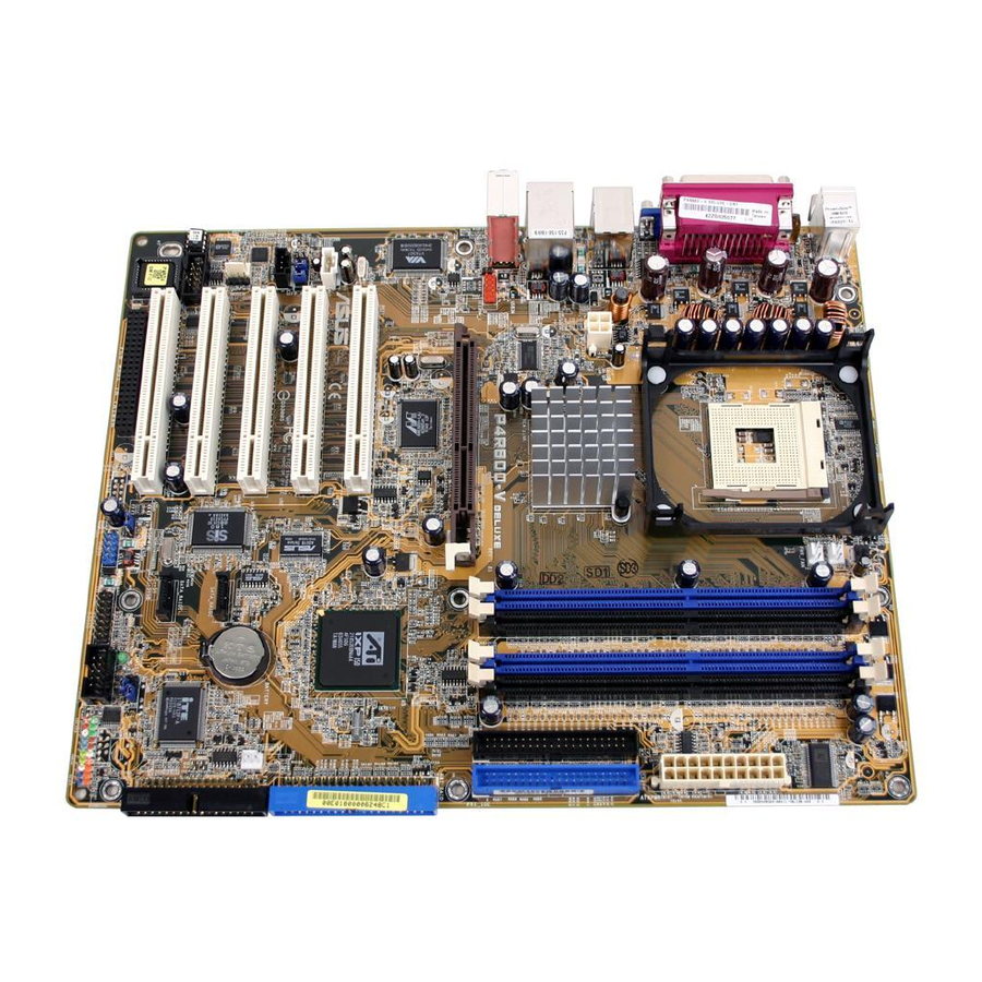
Page 24: Motherboard Layout
Motherboard layout 24.5cm (9.6in) PS/2KBMS T: Mouse CPU_FAN B: Keyboard Socket 478 Composite PWR_FAN S-VHS Bottom: Top: USB1 1394 USB2 ATX12V1 RADEON™ USB2.0 Top: 9100 IGP T: USB3 RJ-45 B: USB4 Top:Line In Center:Line Out P4R800-V Below:Mic In DELUXE IE1394_1 Accelerated Graphics Port (AGP1) Marvell 88E001... -
Page 25: Major Components
20-pin ATX power supply connector 2-26 USB56 10-1 USB 2.0 connector 2-27 CD/AUX/MODEM 4-pin CD/Auxilliary/Modem connectors 2-27 CHA_FAN/CPU_FAN/PWR_FAN 3-pin Chassis/CPU/Power connectors 2-28 FP_AUDIO 10-1 pin Front Audio connector 2-28 PANEL 10-1 pin Panel connector 2-29 ASUS P4R800-V Deluxe motherboard user guide... -
Page 26: Placement Direction
2.2.2 Placement direction When installing the motherboard, make sure that you place it into the chassis in the correct orientation. The edge with external ports goes to the rear part of the chassis as indicated in the image below. 2.2.3 Screw holes Place nine (9) screws into the holes indicated by circles to secure the motherboard to the chassis. -
Page 27: Central Processing Unit (Cpu)
Hyper-Threading Techonology item in BIOS to ensure system stability and performance. ® 2. It is recommended that you install Windows XP Service Pack 1. 3. For more information on Hyper-Threading Technology, visit www.intel.com/info/hyperthreading. ASUS P4R800-V Deluxe motherboard user guide... -
Page 28: Installing The Cpu
2.3.2 Installing the CPU Follow these steps to install a CPU. 1. Locate the 478-pin ZIF socket on the motherboard. 2. Unlock the socket by pressing the lever sideways, then lift it up to a 90°-100° angle. Socket Lever 90 - 100 Make sure that the socket lever is lifted up to 90°-100°... -
Page 29: Installing The Heatsink And Fan
The retention module base is already installed on the motherboard upon purchase. You do not have to remove the retention module base when installing the CPU or installing other motherboard components. CPU Heatsink Retention Module Base ASUS P4R800-V Deluxe motherboard user guide... - Page 30 2. Position the fan with the retention mechanism on top of the heatsink. Align and snap the four hooks of the retention mechanism to the holes on each corner of the module base. Make sure that the fan and retention mechanism assembly perfectly fits the heatsink and module base, otherwise you cannot snap the hooks into the holes.
-
Page 31: Connecting The Cpu Fan Cable
CPU fan cable to the connector on the motherboard labeled CPU_FAN. CPU Fan Connector (CPU_FAN) Don’t forget to connect the CPU fan connector! Hardware monitoring errors may occur if you fail to plug this connector. ASUS P4R800-V Deluxe motherboard user guide... -
Page 32: System Memory
The following figure illustrates the location of the DDR DIMM sockets. P4R800-V DELUXE ® P4R800-V DELUXE 184-Pin DDR DIMM Sockets 2.4.2 Memory configurations You may install 64MB, 128MB, 256MB, 512MB, and 1GB DDR DIMMs into the DIMM sockets using the memory configurations in this section. - Page 33 SS - Single-sided DS - Double-sided When using PC3200 (DDR400) DIMMs, you may install only one module per channel for a maximum of 2GB system memory. DO NOT install two PC3200 modules in one channel. ASUS P4R800-V Deluxe motherboard user guide 2-11...
- Page 34 : Supports 4 modules inserted to both the blue and black slots as two pairs of Dual-channel memory configuration. Legend: SS – Single-sided DS – Double-sided Obtain DDR DIMMs only from ASUS qualified vendors for better system performance. Visit the ASUS website (www.asus.com) for the latest QVL. 2-12 Chapter 2: Hardware information...
-
Page 35: Installing A Dimm
DIMM. Support the DIMM lightly with your fingers when pressing the retaining clips. The DIMM might get damaged when it flips out with extra force. 2. Remove the DIMM from the socket. ASUS P4R800-V Deluxe motherboard user guide 2-13... -
Page 36: Expansion Slots
Expansion slots In the future, you may need to install expansion cards. The motherboard has five PCI, one Accelerated Graphics Port (AGP), and Wi-Fi slots. The following sub-sections describe the slots and the expansion cards that they support. Make sure to unplug the power cord before adding or removing expansion cards. -
Page 37: Interrupt Assignments
When using PCI cards on shared slots, ensure that the drivers support “Share IRQ” or that the cards do not need IRQ assignments. Otherwise, conflicts will arise between the two PCI groups, making the system unstable and the card inoperable. ASUS P4R800-V Deluxe motherboard user guide 2-15... -
Page 38: Pci Slots
AGP cards. P4R800-V DELUXE ® Keyed for 1.5v P4R800-V DELUXE Accelerated Graphics Port (AGP) If installing the ATi 9500 or 9700 Pro Series VGA cards, use only the card version PN xxx-xxxxx-30 or later, for optimum performance and overclocking stability. -
Page 39: Wi-Fi Slot
2.5.6 Wi-Fi slot The Wi-Fi slot supports the ASUS WiFi-b™ card and future IEEE 802.11g network interface card for wireless connectivity. The Wi-Fi slot conforms to the Institute of Electrical and Electronics Engineers (IEEE) 802.11b/g standard for wireless devices operating in the 2.4GHz frequency band. -
Page 40: Jumpers
Clear CMOS Normal (Default) P4R800-V DELUXE Clear RTC RAM You do not need to clear the RTC when the system hangs due to overclocking. For system failure due to overclocking, use the C.P.R. (CPU Parameter Recall) feature. Shut down and reboot the system so BIOS can automatically reset parameter settings to default values. - Page 41 DELUXE USBPW56 ® +5VSB (Default) P4R800-V DELUXE USB Device Wake Up • The USB device wake-up feature requires a power supply that can provide 500mA on the +5VSB lead for each USB port. Otherwise, the system would not power up.
-
Page 42: Connectors
Connectors 2.7.1 Rear panel connectors This section describes and illustrates the rear panel input/output ports. 1. PS/2 mouse port. This green 6-pin connector is for a PS/2 mouse. 2. Parallel port. This 25-pin port connects a parallel printer, a scanner, or other devices. -
Page 43: Internal Connectors
CD-ROM drives, but may be on the opposite side on floppy disk drives. PIN 1 FLOPPY P4R800-V DELUXE NOTE: Orient the red markings on the floppy ribbon cable to PIN 1. ® P4R800-V DELUXE Floppy Disk Drive Connector ASUS P4R800-V Deluxe motherboard user guide 2-21... - Page 44 (usually zigzag) on the IDE ribbon cable to PIN 1. ® PIN 1 P4R800-V DELUXE IDE Connectors 3. GAME/MIDI connector (16-1 pin GAME) This connector supports the bundled USB/GAME module. Connect the USB/GAME module cable to this connector. The GAME/MIDI port on the module connects a joystick or a game pad for playing games, and MIDI devices for playing or editing audio files.
- Page 45 PIN 1. P4R800-V DELUXE RAID Connector If you wish to create a RAID set using UltraATA hard disks, make sure that you have connected the UltraATA cable and installed UltraATA 133 hard disks. ASUS P4R800-V Deluxe motherboard user guide 2-23...
- Page 46 P4R800-V DELUXE PIN 1 PIN 1 ® P4R800-V DELUXE Serial COM2 Bracket 7. Chassis intrusion connector (4-1 pin CHASSIS) This lead is for a chassis designed with intrusion detection feature. This requires an external detection mechanism such as a chassis intrusion sensor or microswitch.
- Page 47 P4R800-V DELUXE SPDIFOUT ® P4R800-V DELUXE Digital Audio Connector The S/PDIF module that comes with the motherboard package has an optical and coaxial S/PDIF Out ports. These ports may not be used simultaneously. ASUS P4R800-V Deluxe motherboard user guide 2-25...
- Page 48 10. ATX power connectors (20-pin ATXPWR, 4-pin ATX12V) These connectors are for the power plugs from the ATX power supply unit. The plugs are designed to fit these connectors in only one orientation. Find the proper orientation and push down firmly until the connectors completely fit.
- Page 49 (such as a phone) and a mono_out (such as a speaker) between the audio and a voice modem card. MODEM Modem-In AUX (White) Ground Ground P4R800-V DELUXE CD (Black) Modem-Out ® P4R800-V DELUXE Internal Audio Connectors ASUS P4R800-V Deluxe motherboard user guide 2-27...
- Page 50 PWR_FAN P4R800-V DELUXE ® CHA_FAN +12V P4R800-V DELUXE Rotation 12-Volt Fan Connectors 14. Front panel audio connector (10-1 pin FP_AUDIO) This is an interface for the Intel front panel audio cable that allow convenient connection and control of audio devices.
- Page 51 Pressing the power switch while in the ON mode for more than 4 seconds turns the system OFF. • Reset Switch Lead (2-pin RESET) This 2-pin connector connects to the case-mounted reset switch for rebooting the system without turning off the system power. ASUS P4R800-V Deluxe motherboard user guide 2-29...
- Page 52 2-30 Chapter 2: Hardware information...
-
Page 53: Chapter 3: Powering Up
Chapter 3 This chapter describes the power up sequence and gives information on the BIOS beep codes and the ASUS POST Reporter™ feature. Powering up... - Page 54 Chapter summary Starting up for the first time ......3-1 BIOS beep codes ........... 3-1 ASUS POST Reporter™ ......... 3-2 Powering off the computer ......3-7 ASUS P4R800-V Deluxe motherboard...
-
Page 55: Starting Up For The First Time
No DRAM installed or detected One long beep followed by Video card not found or video card three short beeps memory bad High frequency beeps when CPU overheated; system is working System running at a lower frequency ASUS P4R800-V Deluxe motherboard user guide... -
Page 56: Asus Post Reporter
ASUS POST Reporter™ feature. This application provides vocal POST messages and alerts to inform you of system events and boot status. In case of a boot failure, the ASUS Post Reporter™ reports the specific cause of the problem. You may customize these POST messages using the Winbond Voice Editor software included in the support CD that came with your motherboard package. - Page 57 Power-On Self Test Computer now booting • No action required from operating system You may enable or disable the ASUS POST Reporter™ by adjusting the Speech IC Reporter BIOS option. See page 4-22 for details. ASUS P4R800-V Deluxe motherboard user guide...
-
Page 58: Winbond Voice Editor
POST messages. Install the software from the utilities menu of the support CD. See section “5.2.3 Utilities menu” for details. To avoid conflicts, do not run the Winbond Voice Editor while running the ASUS PC Probe. Follow these steps to use the Winbond Voice Editor. Launching the Winbond Voice Editor Launch the program either from the Winbond Voice Editor icon on your desktop, or click Start >... - Page 59 For example, use 8-bit, mono quality at 22Khz sampling rate. You may want to create a separate folder for your wave files so you can locate them easily in one place. ASUS P4R800-V Deluxe motherboard user guide...
- Page 60 5. Click the Add button from the Voice Editor screen to display the Add Wave File window. 6. Copy your recorded wave files to the database. Close the window when done. 7. Click a POST event on the Voice Editor screen, then click the Edit button.
-
Page 61: Powering Off The Computer
Using the OS shut down function If you use Windows ® ME/2000/XP, click Start > Shut Down, then the OK button to shut down the computer. The power supply should turn off after ® Windows shuts down. ASUS P4R800-V Deluxe motherboard user guide... - Page 62 Chapter 3: Powering up...
-
Page 63: Chapter 4: Bios Setup
Chapter 4 This chapter tells how to change system settings through the BIOS Setup menus. Detailed descriptions of the BIOS parameters are also provided. BIOS setup... - Page 64 Chapter summary Managing and updating your BIOS ....4-1 BIOS Setup program ........4-8 Main menu ............. 4-11 Advanced menu ........... 4-16 Power menu ..........4-26 Boot menu ............ 4-29 Exit menu ............4-31 ASUS P4R800-V Deluxe motherboard...
-
Page 65: Managing And Updating Your Bios
Basic Input/Output System (BIOS) setup. 1. AwardBIOS Flash Utility (Updates the BIOS using a floppy disk during POST.) 2. ASUS CrashFree BIOS 2 (Updates the BIOS using a bootable floppy disk or the support CD when the BIOS gets corrupted.) ®... -
Page 66: Updating Bios Using The Awardbios Flash Utility
BIOS file. 1. Download the latest BIOS file from the ASUS website (www.asus.com). Rename the file to *.BIN and save it to the bootable floppy disk you created earlier. 2. Insert the disk that contains the new BIOS file into the floppy drive. - Page 67 5. AWDFLASH checks the new BIOS file from the floppy disk. 6. After verification, AWDFLASH flashes the new BIOS file. Do not shut down the computer during the flash process. 7. After the new BIOS file is copied, the computer returns to POST. ASUS P4R800-V Deluxe motherboard user guide...
-
Page 68: Recovering The Bios With Crashfree Bios 2
3. Insert a floppy disk that contains the original, or the latest, BIOS file for this motherboard (P4R800V.BIN). If the BIOS file that you downloaded from the ASUS website has a different filename (e.g. P4R800V_1001.001), rename it to P4R800V.BIN. The BIOS update process continues when the P4R800V.BIN is found. - Page 69 4. When the BIOS update process is complete, reboot the system. The recovered BIOS may not be the latest BIOS version for this motherboard. Visit the ASUS website (www.asus.com) to download the latest BIOS file. ASUS P4R800-V Deluxe motherboard user guide...
-
Page 70: Asus Update
4.1.4 ASUS Update The ASUS Update is a utility that allows you to update the motherboard BIOS in Windows ® environment. This utility is available in the support CD that comes with the motherboard package. ASUS Update requires an Internet connection either through a network or an Internet Service Provider (ISP). - Page 71 If you selected the option to update the BIOS from a file, a window pops up prompting you to locate the file. Select the file, click Save, then follow the screen instructions to complete the update process. ASUS P4R800-V Deluxe motherboard user guide...
-
Page 72: Bios Setup Program
BIOS Setup program This motherboard supports a programmable low pin count (LPC) chip that you can update using the provided utility described in section “4.1 Managing and updating your BIOS.” Use the BIOS Setup program when you are installing a motherboard, reconfiguring your system, or prompted to “Run Setup”. -
Page 73: Bios Menu Screen
The BIOS setup screens shown in this chapter are for reference purposes only, and may not exactly match what you see on your screen. • Visit the ASUS website (www.asus.com) to download the latest BIOS information. ASUS P4R800-V Deluxe motherboard user guide... -
Page 74: Legend Bar
4.2.3 Legend bar At the bottom of the Setup screen is a legend bar. The keys in the legend bar allow you to navigate through the various setup menus. The following table lists the keys found in the legend bar with their corresponding functions. -
Page 75: Main Menu
Up> or <Page Down> keys to change the values. Language [English] This option allows you to change the BIOS Setup language to English, German, or Japanese. You may also press <F3> anytime to change the BIOS Setup language. ASUS P4R800-V Deluxe motherboard user guide 4-11... - Page 76 Legacy Diskette A [1.44M, 3.5 in.] Sets the type of floppy drive installed. Configuration options: [None] [360K, 5.25 in.] [1.2M , 5.25 in.] [720K , 3.5 in.] [1.44M, 3.5 in.] [2.88M, 3.5 in.] Case Open Warning [Enabled] Enable this option to activate the chassis intrusion feature of the motherboard.
- Page 77 In these cases, select [Manual] to manually enter the IDE hard disk drive parameters. If no drive is installed or if you are removing a drive and not replacing it, select [None]. Configuration options: [None] [Auto] [Manual] ASUS P4R800-V Deluxe motherboard user guide 4-13...
- Page 78 Access Mode [Auto] The default [Auto] allows automatic detection of an IDE hard disk drive. Select [CHS] for this item if you set the IDE Channel 0/1 Master/Slave to [Manual] to enter the Hard Disk Drive values manually. Configuration options: [CHS] [LBA] [Large] [Auto] Manual HDD type selection If you wish to manually enter the hard disk information, set the IDE Primary Master item to [Manual], and the Access Mode item to [CHS].
- Page 79 FDISK, to partition and format new IDE hard disk drives. This is necessary so that you can write or read data from the hard disk. Make sure to set the partition of the Primary IDE hard disk drives to active. ASUS P4R800-V Deluxe motherboard user guide 4-15...
-
Page 80: Advanced Menu
Advanced menu CPU Type Intel Pentium(R) 4 Select Menu CPU Speed 2.40GHz CPU Cache RAM 512K Item Specific Help Current FSB Frequency 533MHz Current DRAM Frequency 333MHz USB 2.0 Controller [Enabled] USB Legacy Support [Enabled] Init Display First [PCI Slot] Frequency/Voltage Control Chip Configuration I/O Device Configuration... -
Page 81: Frequency/Voltage Control
Configuration options: [Auto] [Manual] VCore Voltage [X.XXXV] This item is configurable when the VCore Control option is set to [Manual]. Select the VCore voltage from the available options. Configuration options: [1.625V] [1.600V] [1.575V] [1.550V] [1.525V] ASUS P4R800-V Deluxe motherboard user guide 4-17... -
Page 82: Chip Configuration
CPU VCore setup [Auto] This option allows you to increase the CPU VCore voltage. Configuration options: [0.1V] [0.2V] [0.3V] [0.4V] [Auto] NB VCore setup [Auto] This option allows you to select the NB VCore voltage. Configuration options: [1.5V] [1.6V] [Auto] DDR Voltage setup [Auto] This option allows you to select the DDR voltage. - Page 83 Configuration options: [1 Clock] [2 Clocks] [3 Clocks] [4 Clocks] MANUAL TRAS [1 Clock] This field allows you to set the TRAS. Configuration options: [1 Clock] [2 Clocks] [3 Clocks] [4 Clocks] [5 Clock] [6 Clocks] [7 Clocks] [8 Clocks] ASUS P4R800-V Deluxe motherboard user guide 4-19...
- Page 84 SB200 OnChip IDE Device Select Menu Chip Configuration Onboard Pri IDE Controller [Enabled] Item Specific Help Onboard Sec IDE Controller [Enabled] Primary Master [Auto] Press [Enter] to enable Primary Slave [Auto] Primary PCI IDE support. Secondary Master PIO [Auto] Secondary Slave [Auto] Primary Master UDMA...
-
Page 85: I/O Device Configuration
This field sets the parallel port DMA channel for the selected ECP mode. The default setting is 3. This item is available only if you selected [ECP] or [ECP+EPP] as the Parallel Port Mode. Configuration options: [1] [3] ASUS P4R800-V Deluxe motherboard user guide 4-21... - Page 86 This field allows you to enable or disable the onboard speech controller. Configuration options: [Disabled] [Enabled] You must enable this item if you wish to use the ASUS POST Reporter™ feature. See page 3-2 for details. Report IDE Error [Disabled] This option allows you to enable or disable IDE error reporting during the POST.
-
Page 87: Pci Configuration
When set to [Auto (ESCD)], BIOS automatically configures all boot Plug and Play devices. Setting to [Manual] enables the IRQ Resources sub-menu for manual assignment of IRQ addresses Configuration options: [Auto (ESCD)] [Manual] ASUS P4R800-V Deluxe motherboard user guide 4-23... -
Page 88: Irq Resources
IRQ Resources IRQ Resources Select Menu Item Specific Help IRQ-3 assigned to [PCI Device] IRQ-4 assigned to [PCI Device] Legacy ISA for devices IRQ-5 assigned to [PCI Device] compliant with the IRQ-7 assigned to [PCI Device] original PC AT bus IRQ-9 assigned to [PCI Device]... -
Page 89: Instant Music
Instant Music CD-ROM Drive [Secondary Master] Allows you to select the CD-ROM drive that you wish to use for the Instant Music CD playback. Configuration options: [Primary Master] [Primary Slave] [Secondary Master] [Secondary Slave] ASUS P4R800-V Deluxe motherboard user guide 4-25... -
Page 90: Power Menu
Power menu Select Menu ACPI Suspend Type [S1&S3] AC Power Loss Restart [Disabled] Item Specific Help Power Up Control Hardware Monitor Select the ACPI state used for System Suspend. : Help ↑↓ : Select Item : Change Value F5 : Setup Defaults ESC : Exit →←... -
Page 91: Power Up Control
Date and Resume Time fields are activated for manual setup. Configuration options: [Enabled] [Disabled] When you set the RTC Alarm Date to [0], the The system wakes up everyday on the Resume Time you specified. ASUS P4R800-V Deluxe motherboard user guide 4-27... -
Page 92: Hardware Monitor
F10 : Save and Exit Q-Fan Controller [Disabled] This option allows allows you to enable or disable the ASUS Q-Fan feature. Setting to [Enabled] allows the fan to smartly adjust its speed for more efficient system operation. Configuration options: [Disabled] [Enabled] VCORE Voltage [X.XXV]... -
Page 93: Boot Menu
HDD boot sector. Configuration options: [Enabled] [Disabled] Quick Power-On-Self-Test [Enabled] This field speeds up the Power-On-Self Test (POST) routine by skipping retesting several times. Configuration options: [Disabled] [Enabled] ASUS P4R800-V Deluxe motherboard user guide 4-29... - Page 94 Configuration options: [Disabled] [Enabled] Make sure that the Full Screen Logo item is set to [Enabled] if you wish to use the ASUS MyLogo2™ feature. See page 5-13 for details. APIC Mode [Enabled] When enabled, this option allows you to distribute interrupt routings other than the 16 IRQs.
-
Page 95: Exit Menu
This option saves your selections without exiting the Setup program so you may return to other menus and make further changes. After selecting this option, a confirmation window appears. Select [Yes] to save changes to the non-volatile RAM. ASUS P4R800-V Deluxe motherboard user guide 4-31... - Page 96 4-32 Chapter 4: BIOS setup...
-
Page 97: Chapter 5: Software Support
Chapter 5 This chapter describes the contents of the support CD that comes with the motherboard package. Software support... - Page 98 Chapter summary Install an operating system ......5-1 Support CD information ........ 5-1 ATI IGP Catalyst™ .......... 5-7 Software information ........5-10 ASUS P4R800-V Deluxe motherboard...
-
Page 99: Install An Operating System
The contents of the support CD are subject to change at any time without notice. Visit the ASUS website for updates. 5.2.1 Running the support CD To begin using the support CD, place the CD into the optical drive. The CD automatically displays the Drivers menu if Autorun is enabled in your computer. -
Page 100: Drivers Menu
5.2.2 Drivers menu The drivers menu shows the available device drivers if the system detects installed devices. Install the necessary drivers to activate the devices. ATI All in One Driver The item installs the ATI All In One Driver. AD1888 Driver and Application This item installs the AD1888 audio driver and application. -
Page 101: Utilities Menu
This program allows you to download the latest version of the BIOS from the ASUS website. Installing ASUS Update also installs ASUS MyLogo2. See page 4-6 for details. Before using the ASUS Update, make sure that you have an Internet connection so you can connect to the ASUS website. Microsoft DirectX Driver ®... -
Page 102: Asus Contact Information
Use this application if you wish to change the default vocal POST messages. See section 3.3 “ASUS POST Reporter™” for details. ASUS Screen Saver This item installs the ASUS screen saver. 5.2.4 ASUS contact information Click the Contact tab to display the ASUS contact information. Chapter 5: Software support... -
Page 103: Other Information
CD. Click an icon to display the specified information. Motherboard information The window displays the general specifications of the motherboard. Browse this CD The window displays the support CD contents in graphical format. ASUS P4R800-V Deluxe motherboard user guide... - Page 104 Technical support form The window displays the ASUS Technical Support Request Form that you have to fill up when requesting technical support. Filelist The window displays the contents of the support CD and a brief description of each in text format.
-
Page 105: Ati Igp Catalyst
1. Select a BPP and resolution from the menu. A Change Display Settings window appears. The left-click menu displays only the BPP and resolution supported by your display. 2. Select the Refresh Rate, then click Apply. ASUS P4R800-V Deluxe motherboard user guide... -
Page 106: Right-Click Menu
5.3.2 Right-click menu The ATI IGP Catalyst™ right-click menu provides options for configuring your display settings. Displays - This option allows you to set your current display as primary or clone. Schemes - The Schemes option allows you to use a single display or switch among available displays. - Page 107 6. Click Apply to save your changes. Only S-Video signal is available when S-Video and composite video ports are used at the same time. The quality of S-Video is better than composite video. ASUS P4R800-V Deluxe motherboard user guide...
-
Page 108: Software Information
Software information Most of the applications in the support CD have wizards that will conveniently guide you through the installation. View the online help or readme file that came with the software for more information. 5.4.1 Multi-channel audio feature The ADI AD1888 AC ‘97 audio CODEC provides 6-channel audio capability. - Page 109 MIDI. 11. Click the Synthesizer Default Set drop-down menu to display a list of options. Choose the desired setting. 12. Click Apply, then click OK when finished. 13. Reboot the computer. ASUS P4R800-V Deluxe motherboard user guide 5-11...
- Page 110 Adjusting the volume settings 1. After rebooting the system, click on the volume control icon on the ® Windows taskbar to display the Volume Control window. 2. Click the Volume Control Advanced button. The Advanced Controls for Volume Control window appears. To achieve 6-channel audio capability when playing DVDs, check the boxes opposite AC3...
-
Page 111: Asus Mylogo2
5.4.2 ASUS MyLogo2™ The ASUS MyLogo2™ is automatically installed when you install the ASUS Update utility from the support CD. See section 5.2.3 “Utilities menu” for details. Before using ASUS MyLogo2 feature, use the ASUS Update utility to make a copy of your original BIOS file, or obtain the latest BIOS version from the ASUS website. - Page 112 7. When finished, click Exit, then reboot your computer. Your system boots with the new boot logo. Instead of starting from ASUS Update, you may also launch ASUS MyLogo2 directly from the Windows ® Start button menu to change your BIOS boot logo.
-
Page 113: Asus Instant Music
• If the system lost connection or did not detect any optical drive, the Instant Music feature turns OFF (disabled) automatically. A “beep” indicates this condition. ASUS P4R800-V Deluxe motherboard user guide 5-15... - Page 114 To use ASUS Instant Music: 1. Ensure that the power cord is plugged to a grounded power source, so that the system has a standby power. 2. Use either one of the two sets of special function keys on your keyboard to play audio CDs.
-
Page 115: Sis Raid Configurations
(like RAID 1). Refer to the SiS 180 Serial ATA User’s Manual in the support CD for details on the SiS RAID utilities. ASUS P4R800-V Deluxe motherboard user guide 5-17... -
Page 116: Installing The Hard Disks
5.5.1 Installing the hard disks The SiS 180 Serial/Ultra ATA RAID controller supports Serial ATA and Ultra ATA hard disk drives. For optimal performance, install identical drives of the same model and capacity when creating a RAID set. • If you are creating a RAID 0 (striping) array for performance, use two new drives. -
Page 117: Sis Raid Setting Utility
3. Press R to display the RAID setup menu. Creating an array for performance To create a RAID array for performance: 1. In the SiS RAID Setting utility main menu, press A to create array. ASUS P4R800-V Deluxe motherboard user guide 5-19... - Page 118 2. Press <2>, then <Enter> to select Stripe (RAID 0). 3. Press <1>, <7>, then <Enter> to select the Block Size. 4. Press <1>, <2>, then <Enter> to select the Transfer Mode. 5. Use the <Up> or <Down> arrow keys to move the selection bar, then press <Enter>...
- Page 119 8. Press Y then <Enter> to save changes. 9. Once an array is created, partition and initialize your hard disk using the FDISK utility and format the array as a new single hard drive. ASUS P4R800-V Deluxe motherboard user guide 5-21...
-
Page 120: Sisraid Utility
5.5.3 SiSRAID Utility The SiSRAID Utility allows you to create or delete a RAID array in Windows ® . The SiSRAID Utility is automatically copied into your system when you install the SiS RAID Driver. See page 5-2 for details. To launch the SiSRAID Utility: ®... - Page 121 5. After setting all fields and parameters, click the Create button to display the Create Stripe Raidset window. The window displays the source and target disk, and allows you to create or split the data. ASUS P4R800-V Deluxe motherboard user guide 5-23...
- Page 122 Create Stripe Raidset options Source Displays the first selected disk. Target All available disks except the first selected disk. Create Only This operation destroys all data on the selected disk and creates a clean stripe array without any data. Split data (Boot from IDE) This operation will split the data from the source disk into all the selected disks.
-
Page 123: Marvell Virtual Cable Tester™ (Vct) Technology
1. Click Start > All Programs > Marvell > Virtual Cable Tester from the ® Windows desktop. 2. From the menu, click Virtual Cable Tester. The Virtual Cable Tester window appears. 3. Click on Run to execute the test. ASUS P4R800-V Deluxe motherboard user guide 5-25... -
Page 124: Makedisk.exe
Important notes • The Virtual Cable Tester™ (VCT) feature is supported on ® Windows XP and 2000 operating systems only. • The Virtual Cable Tester™ (VCT) feature works only on a system with an installed Marvell Gigabit LAN controller. • The Run button on the VCT Tester dialogue box is disabled if no problem is detected on the network.
Need help?
Do you have a question about the P4R800-V Deluxe and is the answer not in the manual?
Questions and answers