Table of Contents
Advertisement
Advertisement
Table of Contents

Related Manuals for Asus p4p800-VM


Summary of Contents for Asus p4p800-VM
- Page 1 P4P800-VM User Guide...
- Page 2 Product warranty or service will not be extended if: (1) the product is repaired, modified or altered, unless such repair, modification of alteration is authorized in writing by ASUS; or (2) the serial number of the product is defaced or missing.
-
Page 3: Table Of Contents
Creating a bootable floppy disk ......2-2 2.1.2 Using AFUDOS to update the BIOS ...... 2-2 2.1.3 Using ASUS EZ Flash to update the BIOS .... 2-4 2.1.4 Recovering the BIOS with CrashFree BIOS 2 ..2-5 2.2 BIOS Setup program ............2-7... - Page 4 Contents 2.2.1 BIOS menu screen ..........2-8 2.2.2 Menu bar ..............2-8 2.2.3 Navigation keys ............. 2-8 2.2.4 Menu items ............2-9 2.2.5 Sub-menu items ............. 2-9 2.2.6 Configuration fields ..........2-9 2.2.7 Pop-up window ............2-9 2.2.8 Scroll bar ..............2-9 2.2.9 General help ............
-
Page 5: Notices
Notices Federal Communications Commission Statement This device complies with FCC Rules Part 15. Operation is subject to the following two conditions: • This device may not cause harmful interference, and • This device must accept any interference received including interference that may cause undesired operation. -
Page 6: Safety Information
Safety information Electrical safety • To prevent electrical shock hazard, disconnect the power cable from the electrical outlet before relocating the system. • When adding or removing devices to or from the system, ensure that the power cables for the devices are unplugged before the signal cables are connected. -
Page 7: About This Guide
1. ASUS Websites The ASUS websites worldwide provide updated information on ASUS hardware and software products. The ASUS websites are listed in the ASUS Contact Information on page viii. 2. Optional Documentation Your product package may include optional documentation, such as warranty flyers, that may have been added by your dealer. -
Page 8: Asus Contact Information
Technical Support Support Fax: +1-510-608-4555 General Support: +1-502-933-8713 Web Site: www.asus.com Support Email: tsd@asus.com ASUS COMPUTER GmbH (Germany and Austria) Address: Harkortstr. 25, 40880 Ratingen, BRD, Germany General Email: sales@asuscom.de (for marketing requests only) General Fax: +49-2102-9599-31 Technical Support Support Hotline:... -
Page 9: P4P800-Vm Specifications Summary
2 x Serial ATA connectors Audio ADI AD1980 SoundMAX 6-channel audio CODEC Intel 82562EZ LAN PHY supports 10/100 Fast Ethernet Special features ASUS MyLogo ASUS CrashFree BIOS 2 ASUS EZ Flash Wake-on-Ring/LAN/USB/Keyboard/Mouse Suspend-to-RAM (STR) Suspend-to-Disk (STD) HW monitoring Winbond 83627THF supports fan sensors, and temperature... - Page 10 CD/AUX audio connectors Front panel audio connector 20-pin panel connector BIOS features 4Mb Flash ROM, AMI BIOS, ACPI, PnP, DMI2.0, Trend Chip Away Virus (TCAV), ASUS EZ Flash, CrashFree BIOS 2, ASUS MyLogo Industry standard PCI 2.2, USB 2.0 Manageability WfM 2.0, DMI 2.0, WOL/WOR by PME...
-
Page 11: Chapter 1: Product Introduction
Chapter 1 This chapter describes the features of the P4P800-VM motherboard. It includes brief descriptions of the motherboard components, and illustrations of the layout, jumper settings, and connectors. Product introduction... -
Page 12: Welcome
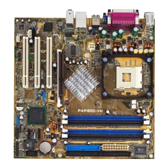
Welcome! Thank you for buying the ASUS ® P4P800-VM motherboard! The ASUS P4P800-VM motherboard delivers a host of new features and latest technologies making it another standout in the long line of ASUS quality motherboards! ® ® The P4P800-VM incorporates the Intel... -
Page 13: Crashfree Bios 2
The motherboard also mounts an AGP 8X interface (a.k.a. AGP 3.0), offering 2.1GB/s bandwidth which is twice that of its predecessor AGP 4X. The slot supports the ASUS DVI card that includes TV, LCD, and digital video output ports. See page 1-17. -
Page 14: Motherboard Components
USB 2.0 technology The motherboard implements the new Universal Serial Bus (USB) 2.0 specification, extending the connection speed from 12 Mbps on USB 1.1 to a fast 480 Mbps on USB 2.0. See pages 1-5 and 1-27. 6-channel digital audio The ADI AD1980 AC’97 audio CODEC is onboard to provide 6-channel audio playback for 5.1 surround sound and over 90dB dynamic range. - Page 15 ASUS P4P800-VM motherboard user guide...
- Page 16 ATX 12V connector. This power connector connects the 4-pin 12V plug from the ATX 12V power supply. CPU socket. A 478-pin surface mount, Zero Insertion Force (ZIF) socket for ® ® the Intel Pentium 4 Processor, with 800/533/400 MHz system bus that allows 6.4GB/s, 4.3GB/s, and 3.2GB/s data transfer rates, respectively.
- Page 17 Video port. This 15-pin port is for a VGA monitor or other VGA-compatile devices. Serial port. This 9-pin COM1 port is for pointing devices or other serial devices. PS/2 keyboard port. This purple connector is for a PS/2 keyboard. ASUS P4P800-VM motherboard user guide...
-
Page 18: Motherboard Layout
Motherboard layout 24.5cm (9.6in) PS/2KBMS T: Mouse B: Keyboard COM1 Socket 478 VGA1 USBPW12 USB1 USB2 USBPW34 Intel ATX12V1 USB2.0 865G Top: T: USB3 RJ-45 Memory B: USB4 Controller Top:Line In Center:Line Out Below:Mic In Accelerated Graphics Port (AGP1) PCI1 CR2032 3V Intel Lithium Cell... -
Page 19: Before You Proceed
SB_PWR1 ® Standby Powered P4P800-VM Onboard LED Power ASUS P4P800-VM motherboard user guide... -
Page 20: Motherboard Installation
Motherboard installation Before you install the motherboard, study the configuration of your chassis to ensure that the motherboard fits into it. The motherboard uses the micro-ATX form factor that measures 9 inches x 9 inches (24.5 cm x 24.5 cm). Make sure to unplug the power cord before installing or removing the motherboard. -
Page 21: Central Processing Unit (Cpu)
2. Power up the system and enter BIOS Setup (see Chapter 2). Under the Advanced Menu, make sure that the item Hyper-Threading Technology is set to Enabled. The item appears only if you installed a CPU that supports Hyper- Threading Techonology. 3. Reboot the computer. ASUS P4P800-VM motherboard user guide 1-11... -
Page 22: Installing The Cpu
1.8.2 Installing the CPU Follow these steps to install a CPU. 1. Locate the 478-pin ZIF socket on the motherboard. 2. Unlock the socket by pressing the lever sideways, then lift it up to a 90°- 100° angle. Socket Lever 90 - 100 Make sure that the socket lever is lifted up to 90°-100°... -
Page 23: System Memory
5. DIMMs installed into any three sockets will function in single-channel mode. 6. When all four sockets are populated with 1GB DIMMs (total 4GB), the system may detect only 3+GB (a little less than 4GB) due to ICH5 resource allocation. ASUS P4P800-VM motherboard user guide 1-13... - Page 24 Table 1 Recommended memory configurations Sockets Mode DIMM_A1 DIMM_A2 DIMM_B1 DIMM_B2 (blue) (black) (blue) (black) Single-channel (1) Populated — — — — Populated — — — — Populated — — — — Populated Dual-channel (1) Populated Populated — — Populated Populated —...
-
Page 25: Installing A Dimm
77.10636.465 Samsung K4H560838D-TCC4 Obtain DDR DIMMs only from ASUS qualified vendors for better system performance. Visit the ASUS website (www.asus.com) for the latest QVL. 1.9.2 Installing a DIMM Make sure to unplug the power supply before adding or removing DIMMs or other system components. -
Page 26: Expansion Slots
1.10 Expansion slots The motherboard has three PCI slots and one Accelerated Graphics Port (AGP) slot. To install and configure an expansion card: 1. Install an expansion card following the instructions that came with the chassis. NOTE: The AGP slot supports only +0.8V or 1.5V AGP cards. 2. -
Page 27: Pci Slots
AGP cards. DVI-865 ® P4P800-VM Accelerated Graphics Port (AGP) If installing the ATi 9500 or 9700 Pro Series VGA cards, use only the card version PN xxx-xxxxx-30 or later, for optimum performance and overclocking stability. ASUS P4P800-VM motherboard user guide 1-17... -
Page 28: Jumpers
1.11 Jumpers 1. Clear RTC RAM (CLRTC1) This jumper allows you to clear the Real Time Clock (RTC) RAM in CMOS. You can clear the CMOS memory of date, time, and system setup parameters by erasing the CMOS RTC RAM data. The RAM data in CMOS, that include system setup information such as system passwords, is powered by the onboard button cell battery. - Page 29 500mA on the +5VSB lead when these jumpers are set to +5VSB. Otherwise, the system would not power up. 2. The total current consumed must NOT exceed the power supply capability (+5VSB) whether under normal condition or in sleep mode. ASUS P4P800-VM motherboard user guide 1-19...
-
Page 30: Floppy Disk Drive Connector
1.12 Connectors This section describes and illustrates the internal connectors on the motherboard. 1. Floppy disk drive connector (34-1 pin FLOPPY) This connector supports the provided floppy drive ribbon cable. After connecting one end to the motherboard, connect the other end to the floppy drive. - Page 31 PIN 1 P4P800-VM IDE Connectors Important note when using legacy OS Refer to page 1-22 on how to configure P-ATA and S-ATA devices if you installed a legacy operating system (e.g. MS-DOS, Windows 98/Me/NT4.0). ASUS P4P800-VM motherboard user guide 1-21...
- Page 32 4. Serial ATA connectors (7-pin SATA1, SATA2) These next generation connectors support the thin Serial ATA cables for Serial ATA hard disks. The current Serial ATA interface allows up to 150 MB/s data transfer rate, faster than the standard parallel ATA with 133 MB/s (Ultra ATA/133). SATA2 SATA1 ®...
- Page 33 ATXPWR1 ATX12V1 +3.3VDC +3.3VDC -12.0VDC +3.3VDC PS_ON# +5.0VDC +12V DC +12V DC +5.0VDC ® -5.0VDC PWR_OK +5.0VDC +5VSB +5.0VDC +12.0VDC P4P800-VM ATX Power Connector ASUS P4P800-VM motherboard user guide 1-23...
- Page 34 6. SMBus connector (6-1 pin SMB1) This connector allows you to connect SMBus (System Management Bus) devices. Devices communicate with an SMBus host and/or other SMBus devices using the SMBus interface. SMB1 ® P4P800-VM SMBus Connector 7. CPU and chassis fan connectors (3-pin CPU_FAN1, CHA_FAN1) The fan connectors support cooling fans of 350mA~740mA (8.88W max.) or a total of 1A~2.22A (26.64W max.) at +12V.
- Page 35 By default, the pins labeled “Chassis Signal” and “Ground” are shorted with a jumper cap. If you wish to use the chassis intrusion detection feature, remove the jumper cap from the pins. CHASSIS1 ® P4P800-VM Chassis Alarm Lead (Default) ASUS P4P800-VM motherboard user guide 1-25...
- Page 36 10. GAME/MIDI connector (16-1 pin GAME1) This connector supports an optional GAME/MIDI module. Connect the GAME/ MIDI cable to this connector. The GAME/MIDI port on the module connects a joystick or a game pad for playing games, and MIDI devices for playing or editing audio files.
- Page 37 USB78 P4P800-VM USB 2.0 Header The USB 2.0/GAME module is purchased separately. 13. MDC connector (4-1 pin MDC1) This connector supports the optional ASUS Modem card module. MDC1 ® P4P800-VM MDC Header The ASUS Modem card module is purchased separately.
- Page 38 14. Digital audio connector (4-1 pin SPDIF1) This connector is for a S/PDIF audio module that allows digital instead of analog sound output. Connect one end of the audio cable to the S/PDIF Out connector on the motherboard, and the other end to the S/PDIF module. The S/PDIF module is purchased separately.
- Page 39 ON mode for more than 4 seconds turns the system OFF. • Reset Switch Lead (2-pin RESET) This 2-pin connector connects to the case-mounted reset switch for rebooting the system without turning off the system power. ASUS P4P800-VM motherboard user guide 1-29...
- Page 40 1-30 Chapter 1: Product introduction...
-
Page 41: Chapter 2: Bios Information
Chapter 2 This chapter tells how to change system settings through the BIOS Setup menus. Detailed descriptions of the BIOS parameters are also provided. BIOS information... -
Page 42: Managing And Updating Your Bios
2.1.2 Using AFUDOS to update the BIOS Update the BIOS using the AFUDOS.EXE utility in DOS environment. 1. Visit the ASUS website (www.asus.com) to download the latest BIOS file for your motherboard. Save the BIOS file to a bootable floppy disk. - Page 43 Copyright (C) 2002 American Megatrends, Inc. All rights reserved. Reading file ..done Erasing flash ..done Writing flash ..0x0008CC00 (9%) Verifying flash .. done A:\> 5. Reboot the system from the hard disk. ASUS P4P800-VM motherboard user guide...
-
Page 44: Using Asus Ez Flash To Update The Bios
If the correct BIOS file is not found in the floppy disk, the error message “P4P800VM.ROM not found!” 4. Insert the floppy disk that contains the BIOS file. If the P4P800VM.ROM file is found in the floppy disk, EZ Flash performs the BIOS update process and automatically reboots the system when done. -
Page 45: Recovering The Bios With Crashfree Bios 2
Checking for floppy... 3. Insert a floppy disk that contains the original, or the latest, BIOS file for this motherboard (P4P800VM.ROM). If the BIOS file that you downloaded from the ASUS website has a different filename (e.g. P4P800VM11.ROM), rename it to P4P800VM.ROM. The BIOS update process continues when the P4P800VM.ROM is found. -
Page 46: To Recover The Bios From The Support Cd
4. When the BIOS update process is complete, reboot the system. The recovered BIOS may not be the latest BIOS version for this motherboard. Visit the ASUS website (www.asus.com) to download the latest BIOS file. Chapter 2: BIOS information... -
Page 47: Bios Setup Program
Because the BIOS software is constantly being updated, the following BIOS setup screens and descriptions are for reference purposes only, and may not exactly match what you see on your screen. ASUS P4P800-VM motherboard user guide... -
Page 48: Bios Menu Screen
Legacy Diskette A [1.44M, 3.5 in] select a field. Primary IDE Master :[ST320413A] Use [+] or [-] to Primary IDE Slave :[ASUS CD-S340] configure system time. Secondary IDE Master :[Not Detected] Secondary IDE Slave :[Not Detected] Third IDE Master :[Not Detected]... -
Page 49: Menu Items
Press Up/Down arrow Scroll bar keys or PageUp/PageDown keys to display the other items on the screen. 2.2.9 General help At the top right corner of the menu screen is a brief description of the selected item. ASUS P4P800-VM motherboard user guide... -
Page 50: Main Menu
Legacy Diskette A [1.44M, 3.5 in] select a field. Primary IDE Master :[ST320413A] Use [+] or [-] to Primary IDE Slave :[ASUS CD-S340] configure system time. Secondary IDE Master :[Not Detected] Secondary IDE Slave :[Not Detected] Third IDE Master :[Not Detected]... - Page 51 When set to Disabled, the data transfer from and to the device occurs one sector at a time. Configuration options: [Disabled] [Auto] PIO Mode [Auto] Selects the PIO mode. Configuration options: [Auto] [0] [1] [2] [3] [4] ASUS P4P800-VM motherboard user guide 2-11...
-
Page 52: Ide Configuration
DMA Mode [Auto] Selects the DMA mode. Configuration options: [Auto] [SWDMA0] [SWDMA1] [SWDMA2] [MWDMA0] [MWDMA1] [MWDMA2] [UDMA0] [UDMA1] [UDMA2] [UDMA3] [UDMA4] [UDMA5] SMART Monitoring [Auto] Sets the Smart Monitoring, Analysis, and Reporting Technology. Configuration options: [Auto] [Disabled] [Enabled] 32Bit Data Transfer [Disabled] Enables or disables 32-bit data transfer. - Page 53 The IDE Port Settings appears only when the item Onboard IDE Operate Mode is set to Compatible Mode. IDE Detect Time Out [35] Selects the time out value for detecting ATA/ATAPI devices. Confgiuration options: [0] [5] [10] [15] [20] [25] [30] [35] ASUS P4P800-VM motherboard user guide 2-13...
-
Page 54: System Information
2.3.7 System Information This menu gives you an overview of the general system specifications. The items in this menu are auto-detected by BIOS. AMI BIOS Version : 08.00.09 Build Date : 04/11/03 : PPVM1035 Processor Type : Intel(R) Pentium(R) 4 CPU 1.73GHz Speed : 1733 MHz Count... -
Page 55: Advanced Menu
This item allows you to enable or disable the processor Hyper-Threading Technology. Configuration options: [Disabled] [Enabled] The item Hyper-Threading Technology appears only if you installed an Intel Pentium 4 CPU that supports this feature. ASUS P4P800-VM motherboard user guide 2-15... -
Page 56: Chipset
2.4.2 Chipset The Chipset menu items allow you to change the advanced chipset settings. Select an item then press Enter to display the sub-menu. Advanced Chipset settings Set the CPU external frequency for next WARNING: Setting wrong values in the sections below boot. - Page 57 Flat Panel Type [640x480 LVDS] Allows selection of flat panel type. Configuration options: [640x480 LVDS] [640x480 CMOS] [800x600 LVDS] [800x600 CMOS] [1024x768 LVDS] [1024x768 CMOS] [1280x1024 LVDS] [1280x1024 CMOS] [1400x1050 LVDS] [1400x1050 CMOS] [1600x1200 LVDS] [1600x1200 CMOS] ASUS P4P800-VM motherboard user guide 2-17...
-
Page 58: Onboard Devices Configuration
TV Standard [Auto] Allows selection of the TV output standard. Configuration options: [Auto] [PAL_B] [SECAM_L] [NTSC_M] [PAL_G] [SECAM_L1] [NTSC_M_J] [PAL_D] [SECAM_B] [NTSC_433] [PAL_H] [NTSC_N] [PAL_I] [PAL_M] [PAL_N] [PAL_60] MPS Revision [1.4] Configuration options: [1.1] [1.4] 2.4.3 Onboard Devices Configuration OnBoard AC’97 Audio [Auto] OnBoard LAN [Enabled]... - Page 59 Allows you to select the Parallel Port IRQ. Configuration options: [IRQ5] [IRQ7] Onboard Game/MIDI Port [Disabled] Allows you to select the Game Port address or to disable the port. Configuration options: [Disabled] [200/300] [200/330] [208/300] [208/330] ASUS P4P800-VM motherboard user guide 2-19...
-
Page 60: Pci Pnp
2.4.4 PCI PnP The PCI PnP menu items allow you to change the advanced settings for PCI/PnP devices. The menu includes setting IRQ and DMA channel resources for either PCI/PnP or legacy ISA devices, and setting the memory size block for legacy ISA devices. - Page 61 When set to [Reserved], the DMA channel is reserved for legacy ISA devices. Configuration options: [Available] [Reserved] Reserved Memory Size [Disabled] Sets the size of memory block reserved for legacy ISA devices. Configuration options: [Disabled] [16K] [32K] [64K] ASUS P4P800-VM motherboard user guide 2-21...
-
Page 62: Usb Configuration
2.4.5 USB Configuration The items in this menu allows you to change the USB-related features. Select an item then press Enter to display the configuration options. USB Configuration Enables USB host controllers. Module Version : 2.22.4-5.3 USB Devices Enabled : None USB Function [8 USB Ports] Legacy USB Support... -
Page 63: Usb Mass Storage Device Configuration
When set to Auto, USB devices less than 530MB will be emulated as floppy drive, and the remaining drives as hard drives. Forced FDD option can be used to force an HDD formatted drive to boot as FDD (for example, ZIP drive). ASUS P4P800-VM motherboard user guide 2-23... -
Page 64: Power Menu
Power menu The Power menu items allow you to change the settings for the Advanced Power Management (APM). Select an item then press Enter to display the configuration options. Suspend Mode [Auto] Configure CPU. Repost Video on S3 Resume [No] ACPI 2.0 Support [No] ACPI APIC Support... -
Page 65: Apm Configuration
Allows you to select the duty cycle in throttle mode. Configuration options: [87.5%] [75.0%] [62.5%] [50%] [37.5%] [25%] [12.5%] System Thermal [Disabled] Allows you to enable or disable the system thermal feature to generate a power management event. Configuration options: [Disabled] [Enabled] ASUS P4P800-VM motherboard user guide 2-25... - Page 66 Power Button Mode [On/Off] Allows the system to go into On/Off mode or suspend mode when the power button is pressed. Configuration options: [On/Off] [Suspend] Restore on AC Power Loss [Power Off] When set to Power Off, the system goes into off state after an AC power loss. When set to Power On, the system goes on after an AC power loss.
-
Page 67: Hardware Monitor
If any of the monitored items is out of range, the following error message appears: “Hardware Monitor found an error. Enter Power setup menu for details”. You will then be prompted to “Press F1 to continue or DEL to enter SETUP”. ASUS P4P800-VM motherboard user guide 2-27... -
Page 68: Boot Menu
Specifies the boot sequence from the 1st Boot Device [First Floppy Drive] available devices. 2nd Boot Device [PM-ST320413A] 3rd Boot Device [PS-ASUS CD-S340] A device enclosed in parenthesis has been disabled in the corresponding type menu. Select Screen Select Item... -
Page 69: Boot Settings Configuration
[Disabled] [Enabled] Typematic Rate [Fast] Allows you to select the keyboard typematic rate. Configuration options: [Slow] [Fast] Parity Check [Disabled] Allows you to enable or disable the memory parity error checking. Configuration options: [Disabled] [Enabled] ASUS P4P800-VM motherboard user guide 2-29... -
Page 70: Security
Boot to OS/2 [No] Allows you to specify the OS/2 compatibility mode. Configuration options: [No] [Yes] Wait for ‘F1’ If Error [Enabled] When set to Enabled, the system waits for F1 key to be pressed when error occurs. Configuration options: [Disabled] [Enabled] Hit ‘DEL’... -
Page 71: Change Supervisor Password
View Only allows access but does not allow change to any field. Limited allows change to only selected fields, such as Date and Time. Full Access allows viewing and changing all the fields in the Setup utility. ASUS P4P800-VM motherboard user guide 2-31... -
Page 72: Change User Password
Change User Password Select this item to set or change the user password. The User Password item on top of the screen shows the default Not Installed. After you have set a password, this item shows Installed. To set a User Password: 1. -
Page 73: Exit Menu
Setup menus. When you select this option or if you press <F5>, a confirmation window appears. Select [Yes] to load default values. Select Exit Saving Changes or make other changes before saving the values to the non-volatile RAM. ASUS P4P800-VM motherboard user guide 2-33... - Page 74 2-34 Chapter 2: BIOS information...
-
Page 75: Chapter 3: Software Support
Chapter 3 This chapter describes the contents of the support CD that comes with the motherboard package. Software support... -
Page 76: Install An Operating System
The contents of the support CD are subject to change at any time without notice. Visit the ASUS website for updates. 3.2.1 Running the support CD To begin using the support CD, simply insert the CD into your CD-ROM drive. The CD automatically displays the Drivers menu if Autorun is enabled in your computer. -
Page 77: Drivers Menu
® Intel PRO LAN Driver This item installs the Intel PRO Fast Ethernet driver to support 10/100 Mbps networking. 3.2.3 Utilities menu The Utilities menu shows the applications and other software that the motherboard supports. ASUS P4P800-VM motherboard user guide... -
Page 78: Install Asus Update
Install ASUS Update This program allows you to download the latest version of the BIOS from the ASUS website. Before using the ASUS Update, make sure that you have an Internet connection so you can connect to the ASUS website. Installing ASUS Update also installs ASUS Mylogo™. -
Page 79: Software Information
10. The MIDI Music Synthesizer screen allows you to select a setting for the MIDI. 11. Click the arrow under Synthesizer Default Set to display a list of options. Choose your desired setting. 12. Click Apply, then click OK when done. ASUS P4P800-VM motherboard user guide... -
Page 80: Rear Panel Audio Ports Function Variation
Adjusting the volume settings 1. After rebooting the system, click on the volume control icon on the taskbar (lower right corner of your desktop) to display the Volume Control panel. Volume control icon 2. If you installed an S/PDIF module, click on the Volume Control Advanced button from the Volume Control panel.