
Related Manuals for IBM 1735-2GX


Summary of Contents for IBM 1735-2GX
- Page 1 Global 2x16 Console Manager Global 4x16 Console Manager Installation and User’s Guide For 1735-2GX and 1735-4GX...
- Page 3 Global 2x16 Console Manager Global 4x16 Console Manager Installation and User’s Guide...
- Page 6 For example, if a caution statement begins with a number 1, translations for that caution statement appear in the IBM Safety Information book under statement 1. Be sure to read all caution and danger statements in this documentation before performing the instructions.
-
Page 9: Table Of Contents
T A B L E O F C ON T E N T S Table of Contents List of Figures ......................... xi List of Tables ......................... xiii Chapter 1: Product overview ..................1 Features and benefits......................... 1 Authorization and authentication ...................... 2 SNMP .............................. - Page 10 viii Global Console Manager Installation and User’s Guide Remote configuration options....................22 Configuring the appliance IP address..................23 Configuring users accounts and user device access using the Web interface......... 23 Chapter 3: Using the Web Interface ................25 Supported browsers ......................... 25 Upgrading GCM2 and GCM4 appliances to use the Web interface ..........
- Page 11 TABLE OF CONTENTS Connecting to a target device ......................62 Configuring and starting local virtual media sessions ..............62 Configuring the appliance and the OSCAR interface..............64 Assigning target device names....................65 Configuring ports on cascade devices..................66 Changing the display behavior....................68 Selecting the display language ....................
- Page 12 Global Console Manager Installation and User’s Guide Appendix B: Virtual media ....................... 91 Appendix C: UTP cabling......................93 Appendix D: Technical specifications ..................95 Appendix E: Getting help and technical assistance ..............97 Appendix F: Notices ......................... 99 Index..........................107...
-
Page 13: List Of Figures
LIST OF FIGU RES L i s t o f F i g u r e s Figure 1.1: GCM2 or GCM4 appliance .................... 1 Figure 1.2: Examples of CO cables....................3 Figure 1.3: Cat5 cable and a terminator connected to RJ-45 ports on a UCO cable ...... 4 Figure 1.4: Example appliance configuration................... - Page 14 Global Console Manager Installation and User’s Guide Figure 3.23: Save Appliance Configuration window ..............55 Figure 3.24: Restore Appliance Configuration window..............56 Figure 3.25: Save Appliance User Data window ................57 Figure 3.26: Restore Appliance User Data window................ 58 Figure 4.1: Example of a Main window ..................59 Figure 4.2: Setup window ........................
- Page 15 xiii LIST OF TABLES L i s t o f T a b l e s Table 1.1: GCM2 and GCM4 appliance model comparison............. 6 Table 2.1: Earlier model switches configuration for the (2048(maximum number of target devices . Table 2.2: Local configuration options ................... 22 Table 2.3: Remote configuration options ..................
- Page 16 Global Console Manager Installation and User’s Guide...
-
Page 17: Chapter 1: Product Overview
® The IBM Global 2x16 Console Manager (GCM2) and the IBM Global 4x16 Console Manager (GCM4) appliances integrate digital and analog KVM switching technology with advanced cable management and provide access for up to three or four simultaneous users. Virtual media support is included. -
Page 18: Authorization And Authentication
Global Console Manager Installation and User’s Guide Users can access connected target devices remotely through the1000BASE-T Ethernet port and directly through a local user station. IP access through standard LAN connections supports target device control from anywhere in the world. Both appliance models have USB and PS/2 ports for one local user station. -
Page 19: Conversion Option Cables
CO cable models support target devices with either PS/2 and USB ports. You must connect one of the following types of CO cables to each target device: • IBM 250 mm KVM Conversion Option (KCO) cable - PS/2 and VGA connectors • IBM 1.5 M KVM Conversion Option (KCO) cable - PS/2 and VGA connectors •... -
Page 20: Oscar Graphical User Interface
Global Console Manager Installation and User’s Guide • When target devices are daisy chained from a single ARI port, a Cat5 cable must be connected to the second RJ-45 port on a KCO or UCO that is connected to a target device. The other end of the Cat5 cable must then be connected to the first RJ-45 port on a KCO or UCO cable that is connected to the next target device in the chain. -
Page 21: Video
Chapter 1: Product overview Video The appliance provides optimal resolution for analog VGA, SVGA, and XGA video. Resolutions of up to 1280 x 1024 can be achieved depending upon the length of cable that is separating the appliance and target devices. Flash upgradability The appliance firmware can be upgraded to a more-current version using the Web interface, the OSCAR interface, the VCS, or the Console menu. -
Page 22: Example Appliance Configuration
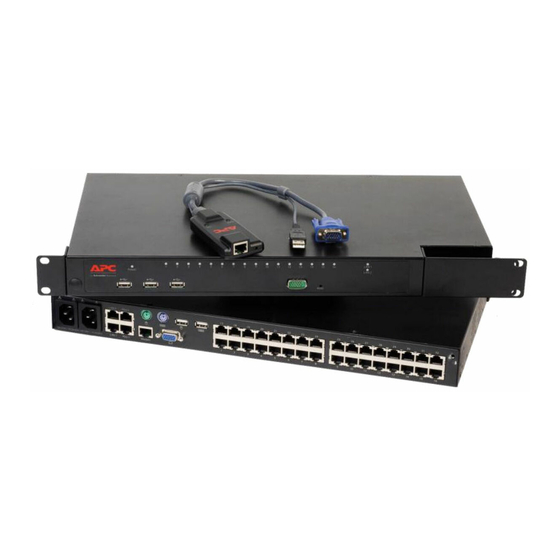
Global Console Manager Installation and User’s Guide Example appliance configuration Rack of target devices GCM2 or GCM4 appliance Ethernet Virtual media device Remote user Local user Remote user Figure 1.4: Example appliance configuration Table 1.1: GCM2 and GCM4 appliance model comparison Model Ports Remote Local... -
Page 23: Chapter 2: Installation
CHAPTER Installation The following tasks to set up and configure the appliance are described in this chapter: Unpack the appliance and verify that all components are present and in good condition. See “Required items” on page 9. Make the needed mouse setting adjustments on each target device to be connected. See “Required adjustments to mouse and cursor settings”... -
Page 24: Figure 2.1: Basic Appliance Configuration
Global Console Manager Installation and User’s Guide The following diagram illustrates one possible configuration for the appliance. Network Local user Digital user Cat5 cable 1-16 Power ARI ports cord Virtual media device* Peripherals Target devices 1-16 * To allow a virtual media session with a target device, the target device must have a VCO cable attached. -
Page 25: Required Items
The following additional items are needed: • A Phillips screwdriver • For each target device to be connected, one IBM Conversion Option (KCO, UCO, or VCO) and one Cat5 cable • For each switch to be tiered, one Cat5 cable. -
Page 26: Required Adjustments To Mouse And Cursor Settings
Global Console Manager Installation and User’s Guide Computers used to access the Web interface and client computers running the VCS must have one of the following browsers installed: • Internet Explorer 7.0 or later • Netscape 7.0 or later • Firefox 2.0 or later Computers used to access the Web interface and client computers running the VCS must have Java Runtime Environment JRE 5.0 update 11 installed. - Page 27 Chapter 2: Installation...
- Page 28 Global Console Manager Installation and User’s Guide General • Observe and follow service markings. • Do not service any appliance except as explained in the appliance documentation. • Opening or removing covers that are marked with the triangular symbol with a lightning bolt might expose you to electrical shock.
-
Page 29: Rack Mounting The Appliance
Chapter 2: Installation • Keep the appliance away from radiators and heat sources. Also, do not block cooling vents. • Do not spill food or liquids on the appliance components, and never operate the appliance in a wet environment. If the appliance gets wet, see the applicable section in the troubleshooting guide or contact the trained service provider. -
Page 30: General Guidelines
Global Console Manager Installation and User’s Guide General guidelines • Refer to the rack installation documentation that accompanied the rack for specific caution statements and procedures. • Elevated ambient temperature: In a closed rack assembly, the operation temperature of the rack environment can be greater than room ambient. -
Page 31: Installing The Appliance Horizontally In The 1-U Rack Mounting Space
Chapter 2: Installation Figure 2.2: Appliance vertical installation Installing the appliance horizontally in the 1-U rack mounting space NOTE: The filler panel must be placed in front of the rack when the appliance is mounted in the horizontal 1-U orientation. To install the appliance horizontally, complete the following steps: Remove the screws on each side of the appliance. -
Page 32: Connecting Hardware To The Appliance
Global Console Manager Installation and User’s Guide Connecting hardware to the appliance To connect and turn on the appliance, complete the following steps: Turn off the target devices that are part of the switching system. Connect one end of the supplied power cord to the back of the appliance and connect the other end of the cord to an ac power source. -
Page 33: Daisy Chaining
Chapter 2: Installation Daisy chaining You can daisy chain up to 16 target devices from each ARI port allowing up to 256 target devices to be managed by a single GCM2 or GCM4 appliance. To daisy chain target devices, complete the following steps: Connect one end of a Cat5 cable to the second RJ-45 port on a KCO or UCO cable that is connected to a target device. -
Page 34: Figure 2.4: Appliance Configuration With A Single Tiered Appliance
Global Console Manager Installation and User’s Guide Local user GCM2 appliance (main) ARI ports Primary target devices Tiered (secondary) LCM2 appliance ACI port Secondary target devices Figure 2.4: Appliance configuration with a single tiered appliance... -
Page 35: Figure 2.5: Tiering An Earlier-Model Appliance
By connecting to a KCO that is connected to the local user ports on an earlier-model switch Local user GCM2 or GCM4 appliance KCO cable KCO cable Cat5 cable IBM NetBAY 1x4 IBM NetBay 2x8 Console Switch Console Switch Target device 2 Target device 1 Figure 2.5: Tiering an earlier-model appliance... - Page 36 The following earlier-model switches are compatible with the GCM2 and GCM4 appliances: • IBM NetBAY 1x4 Console Switch • IBM NetBAY 2x8 Console Switch • IBM NetBAY ACT Remote Console Manager • IBM NetBAY ACT Local Console Manager • IBM 1x8 Console Switch • IBM 2x16 Console Switch When tiering earlier-model switches, make sure a GCM2 or GCM4 appliance is the primary (or main) appliance at the top level of the tier.
-
Page 37: Configuring Tiering For The Maximum Number Of Target Devices
Console Manager (LCM2) appliances to the ARI ports of one GCM2 or GCM4 appliance. From the eight ARI ports on the LCM2 secondary appliances, you can either tier eight IBM 2x16 Console Switch appliances or you can daisy-chain 16 target devices. -
Page 38: Local Configuration Options
Global Console Manager Installation and User’s Guide Local configuration options By default, the OSCAR interface and the Console menu are available to any user who is able to access the local user station or a terminal connected to the serial configuration port. Table 2.2: Local configuration options How authentication is Option... -
Page 39: Configuring The Appliance Ip Address
Chapter 2: Installation Configuring the appliance IP address Users enter the IP address for the appliance in a browser to access the Web interface. Administrators can initially configure the IP address using either the Console menu, the OSCAR interface or the VCS. Both DHCP and static IP addressing are supported. The use of a static IP address is recommended. - Page 40 Global Console Manager Installation and User’s Guide Click Save to enable the user’s access to devices. 10. Repeat steps 5 to 9 until all users are configured. 11. Click Logout to exit from the Web interface.
-
Page 41: Chapter 3: Using The Web Interface
CHAPTER Using the Web Interface The integrated Web interface is accessed from a computer that has network access to the appliance. The user enters the IP address configured for the appliance in a supported browser and logs into the Web interface when prompted. Administrators can use the Web interface for viewing all system status and for system configuration. - Page 42 To upgrade appliance firmware, complete the following steps: Download a version of the firmware that includes support for the Web interface from: http:// www.ibm.com/support/ either onto the computer that is running the VCS or onto a TFTP server. In the VCS Appliances window, select the appliance, and click the Tools tab.
- Page 43 Chapter 3: Using the Web Interface Select each appliance to be migrated and click > to move the appliance from the Available Appliances list to the Appliances to migrate list. To use the local database appliance information, select the Use Local Database Information check box.
-
Page 44: Web Interface Window
GCM2 and GCM4 Installation and User’s Guide Web interface window This section gives an overview of the tabs, defines the Path numbering conventions, and the Reboot Required button. Figure 3.1: Web interface window with Connections tab selected and Reboot Required button The Web interface has four tabs: Connections, Configure, Status, and Tools. -
Page 45: Port Numbers In Path Columns
Chapter 3: Using the Web Interface • Connections - Connect to target devices. See "Connecting to target devices" on page 31. • Status - View session status and disconnect sessions. See "Viewing and disconnecting session status" on page 32. • Configure - Configure the appliance network parameters, KVM session parameters (timeouts, encryption, sharing options), user accounts and user target device access, SNMP, servers, and CO cables. -
Page 46: User Access Rights
GCM2 and GCM4 Installation and User’s Guide and the cursor on the computer from which you are accessing the switching system. The Viewer is described in the VCS Installation and User’s Guide. User access rights Three access rights are defined: User, User Administrator, and Appliance Administrator. The access rights (or levels) assigned to a user account affect which target devices the user can access, and whether the user can preempt existing KVM sessions or view existing KVM sessions in stealth mode. -
Page 47: Connecting To Target Devices
Chapter 3: Using the Web Interface Connecting to target devices When the Connections tab is clicked, the window displays a list of target devices that are directly connected and daisy chained to the GCM2 or GCM4 appliance and that are connected or daisy chained to any cascade device. -
Page 48: Viewing And Disconnecting Session Status
GCM2 and GCM4 Installation and User’s Guide If another user does not have an active KVM session with the target device, the Video Viewer window appears. • If another user has an active KVM session with the target device, and sharing is not enabled, or if the number of port sessions has been exceeded, a message window displays and you are denied access to the target device. -
Page 49: Overview Of Viewing And Configuring Appliance Parameters
Chapter 3: Using the Web Interface Figure 3.2: Status window To disconnect user session(s), complete the following steps. Select the check box for one or more sessions. Click the Disconnect Session button. A confirmation window appears. Click OK. The Tools window appears. Overview of viewing and configuring appliance parameters When the Configure tab is selected, Admin and other users with Appliance Administrator and User Administrator rights can view appliance information. -
Page 50: Configuring Network Parameters, Kvm Sessions, Virtual Media, And Authentication
GCM2 and GCM4 Installation and User’s Guide Figure 3.3: Configure tab with left menu options and Appliance window To view appliance information, complete the following steps: Log into the Web interface as a user with Appliance Administrator or User Administrator rights. -
Page 51: Figure 3.4: Appliance Sessions Window
Chapter 3: Using the Web Interface To configure sessions, complete the following steps: Log into the Web interface as a user with Appliance Administrator rights. Click Configure > Appliance > Sessions. Figure 3.4: Appliance Sessions window Configure Video Session parameters by performing the following steps. Select the Session Timeout check box and enter a number of minutes to elapse before inactive video sessions are closed. -
Page 52: Figure 3.5: Appliance > Authentication Window
GCM2 and GCM4 Installation and User’s Guide To enable administrators to monitor sessions secretly, select the Stealth check box. To specify a time period to elapse before the appliance transfers keyboard and mouse control from a primary user to a secondary user, enter 1 to 5 seconds in the Input Control Timeout field. -
Page 53: Figure 3.6: Appliance > Authentication Window
Chapter 3: Using the Web Interface To lock virtual media sessions to KVM sessions, select the Lock to KVM Session check box. To allow primary users to have exclusive virtual media sessions, select the Allow Reserved Sessions check box. Reserved sessions remain active when the associated KVM session is closed. - Page 54 GCM2 and GCM4 Installation and User’s Guide databases are checked. The Authentication Parameters area on the window also becomes active. NOTE: Local authentication is always used, whether it is the primary or backup authentication method, and it cannot be disabled. Select either the Use Local First or Use LDAP First radio button.
-
Page 55: Configuring Users And User Access Rights
Chapter 3: Using the Web Interface Configuring users and user access rights When the Configure tab is selected, the Admin and other users with Appliance Administrator and User Administrator rights can click on the Users option in the left menu to configure user accounts. Figure 3.7: Users window To configure users and user access rights, complete the following steps: Log into the Web interface as a user with Appliance Administrator or User Administrator... -
Page 56: Figure 3.8: Add/Modify User Window
GCM2 and GCM4 Installation and User’s Guide Figure 3.8: Add/Modify User window Click Appliance Administrator, User Administrator, or User from the pull-down User Access Level menu. If User is selected, the Set User Access Rights button becomes active. Click the Set User Access Rights button to select individual target devices for that user.The User Access window appears. -
Page 57: Enabling Security Lock-Out And Unlocking User Accounts
Chapter 3: Using the Web Interface To change a password, complete the following steps: Log into the Web interface as a user with Appliance Administrator or User Administrator rights. Click the Configure tab. In the left menu, click Users. Click a user name in the Users column to modify an existing user. The Add/Modify User window appears. -
Page 58: Configuring Snmp
GCM2 and GCM4 Installation and User’s Guide To unlock an account, complete the following steps: Log into the Web interface as a user with Appliance Administrator or User Administrator rights. Click the Configure tab and then click Users in the left menu. Select the check box next to the user name. -
Page 59: Configuring Snmp Traps
Chapter 3: Using the Web Interface Figure 3.10: SNMP Configuration window To configure general SNMP settings, complete the following steps: Log into the Web interface as a user with Appliance Administrator rights. Click the Configure tab, and then click SNMP in the left menu. Select or clear the Enable SNMP check box to enable or disable SNMP. -
Page 60: Figure 3.11: Snmp Traps Window
GCM2 and GCM4 Installation and User’s Guide Figure 3.11: SNMP Traps Window To configure SNMP traps, complete the following steps: Log into the Web interface as a user with Appliance Administrator rights. Click the Configure tab and then click SNMP > Traps in the left menu. Select or clear the Enabled Traps check box to enable or disable traps. -
Page 61: Viewing Target Device Information And Naming Target Devices
Chapter 3: Using the Web Interface Viewing target device information and naming target devices When the Configure tab is selected, the Admin and other users with Appliance Administrator and User Administration rights can click the Servers option in the left menu to view information about target devices. -
Page 62: Viewing Co Cable Information And Setting A Co Language
GCM2 and GCM4 Installation and User’s Guide To modify the name of a target device, complete the following steps: Log into the Web interface as a user with Appliance Administrator rights. Click the Configure tab and then click Servers in the left menu. Click the name of the server. -
Page 63: Viewing And Configuring Cascade Devices
Chapter 3: Using the Web Interface Figure 3.14: Servers - COs window Viewing and configuring cascade devices When the Configure tab is selected, the Admin and other users with Appliance Administrator or User Administration rights can click the Servers > Cascade Devices option in the left menu to view information about each cascade device (either a GCM2 or GCM4 appliance or legacy switches tiered from the appliance): its Electronic ID number (EID), its Path (port), and the number of channels on the cascade device. -
Page 64: Viewing Software And Firmware Versions For The Appliance
GCM2 and GCM4 Installation and User’s Guide To configure a cascade device name and the number of channels, complete the following steps: Log into the Web interface as a user with Appliance Administrator rights. Click the Configure tab, and then click Cascade Devices in the left menu. Click the name of the cascade device. -
Page 65: Figure 3.17: Cos Firmware Version Window
Chapter 3: Using the Web Interface Admin and other users with Appliance Administrator rights can configure firmware upgrades for individual CO cables and enable automatic firmware upgrades for CO cables. Appliance Administrators can upgrade all CO cables of the same type at once in the Tools tab. See "Using the Tools"... -
Page 66: Figure 3.18: Co Version Window
GCM2 and GCM4 Installation and User’s Guide Figure 3.18: CO Version window Click the X in the upper right of the window to return to the CO Versions window. To configure automatic or individual CO cable firmware upgrades, complete the following steps: Log into the Web interface as a user with Appliance Administrator rights. -
Page 67: Using The Tools
Chapter 3: Using the Web Interface To reset a CO cable, complete the following steps: Log into the Web interface as a user with Appliance Administrator rights. Click the Configure tab, and then click Versions > CO in the left menu. Click the eID of the KCO cable you want to reset. -
Page 68: Upgrading The Appliance Firmware Using The Tools
25 to upgrade the firmware, migrate and resync the appliance after the upgrade. To upgrade appliance firmware, complete the following steps: Download the appliance firmware from http://www.ibm.com/support/ either to a TFTP server or to the current computer. Log into the Web interface as a user with Appliance Administrator rights. -
Page 69: Upgrading Firmware On Multiple Co Cables Using The Tools
Chapter 3: Using the Web Interface To upgrade firmware from the current computer, select the File System radio button and browse to the location on your file system where the firmware file is located. Click Open. Figure 3.21: Upgrade Appliance Firmware window - file system Click the Upgrade button. -
Page 70: Managing Appliance Configuration Files
GCM2 and GCM4 Installation and User’s Guide Figure 3.22: Upgrade CO Firmware window Click Upgrade. The Upgrade button dims. The Last Status column displays either In Progress or Succeeded, depending on the status of each CO cable upgrade. A firmware upgrade currently in progress message displays until all of the selected CO cable types are upgraded. -
Page 71: Figure 3.23: Save Appliance Configuration Window
Chapter 3: Using the Web Interface Figure 3.23: Save Appliance Configuration window (Optional) Enter a password in the File Password field, then repeat the password in the Verify File Password field. If a file password is configured, the administrator must supply this password when attempting to restore the appliance configuration. -
Page 72: Managing User Databases
GCM2 and GCM4 Installation and User’s Guide Figure 3.24: Restore Appliance Configuration window Click Browse and navigate to the location where the saved configuration file is stored. The file name and location appear in the File name field. If a file password was created, enter it in the File Password field. Click Restore. -
Page 73: Figure 3.25: Save Appliance User Data Window
Chapter 3: Using the Web Interface Figure 3.25: Save Appliance User Data window (Optional) Enter a password in the File Password field, then repeat the password in the Verify File Password field. If a file password is configured here, the administrator must supply this password to restore the appliance configuration. -
Page 74: Figure 3.26: Restore Appliance User Data Window
GCM2 and GCM4 Installation and User’s Guide Figure 3.26: Restore Appliance User Data window Click Browse and navigate to the location where the saved user data file is stored. Select the file. The file name and location appear in the File name field. If a file password was created, enter it in the File Password field. -
Page 75: Chapter 4: Using The Oscar Interface
CHAPTER Using the OSCAR interface You can connect a keyboard, monitor, and mouse to local ports on the back of the appliance to act as a local user station for direct analog access. A local user can then use the OSCAR interface to configure the switching system and access target devices. -
Page 76: Table 4.1: Oscar Interface Status Symbols
Global Console Manager Installation and User’s Guide The status of each target device in the switching system is indicated by one or more status symbols in the right column. The following table describes the status symbols. Table 4.1: OSCAR interface status symbols Symbol Description The CO cable is online (green circle). -
Page 77: Using The Oscar Interface
Chapter 4: Using the OSCAR interface Using the OSCAR interface This table describes the keys, key combinations, and mouse actions that you can use in the OSCAR interface. Two or more key names or mouse actions that are separated by commas indicate a sequence of actions. -
Page 78: Connecting To A Target Device
Global Console Manager Installation and User’s Guide Table 4.2: OSCAR interface navigation basics (Continued) Key, key combination, or Result mouse action Start the screen saver immediately and lock the user, if it is Print Screen, Pause password-protected. Up Arrow or Down Arrow Move the cursor from line to line in a list. - Page 79 Chapter 4: Using the OSCAR interface Virtual media sessions created in any manner require that the target device is connected using a VCO cable. NOTE: All USB ports are assigned to a single virtual media session and cannot be independently mapped. To configure virtual media sessions, complete the following steps: Start the OSCAR interface.
-
Page 80: Configuring The Appliance And The Oscar Interface
Global Console Manager Installation and User’s Guide Configuring the appliance and the OSCAR interface You can use the OSCAR interface Setup window to configure the appliance and the OSCAR interface. Figure 4.2: Setup window The following table describes the options in the Setup window. Table 4.3: Setup features to manage routine tasks for the target devices Option Purpose... -
Page 81: Assigning Target Device Names
Chapter 4: Using the OSCAR interface Assigning target device names Use the Names window to identify individual target devices by name rather than by port number. The Names list is always sorted by port order. Names are stored in the CO cable, so even if you move the cable or target device to another ARI port, the name and configuration are recognized by the appliance. -
Page 82: Configuring Ports On Cascade Devices
The GCM2 or GCM4 appliance automatically discovers attached tiered appliances and switches (cascade devices), but you must specify the number of ports on each cascade device through the Devices window. IBM Console Switches and other earlier-model appliances are listed in the Type category for the tiered appliance. -
Page 83: Figure 4.5: Devices Window
Chapter 4: Using the OSCAR interface Figure 4.5: Devices window When the appliance discovers a tiered appliance or switch, the port numbering changes to identify each connected target device. When you select a configurable target device from the list, the Modify button becomes available, so you can configure the correct number of ports. -
Page 84: Changing The Display Behavior
Global Console Manager Installation and User’s Guide Changing the display behavior Use the Menu window to change the order of the target devices and set a screen delay for the OSCAR interface. The display order setting affects the order in which target devices are listed in several windows, including the Main, Devices, and Broadcast windows. -
Page 85: Selecting The Display Language
Chapter 4: Using the OSCAR interface when Print Screen is pressed and when the OSCAR interface starts. To set a screen delay, complete the following steps: In the Menu window, in the Screen Delay Time section, type the number of seconds (0 through 9) to specify the length of delay. -
Page 86: Figure 4.9: Flag Setup Window
Global Console Manager Installation and User’s Guide Table 4.4: OSCAR interface status flags (Continued) Flag Description Flag indicating that the user has been disconnected from all systems. Flag indicating that Broadcast mode is enabled. To specify the status-flag settings, complete the following steps: 1. -
Page 87: Setting The Keyboard Country Code
Chapter 4: Using the OSCAR interface Figure 4.10: Set Position window Click OK to save the changes, or click X or press Escape to exit without saving the changes. Setting the keyboard country code By default, the appliance sends the US keyboard country code to USB cables attached to target devices, and the code is applied to the target devices when they are turned on or rebooted. -
Page 88: Setting Appliance Security
Global Console Manager Installation and User’s Guide Setting appliance security When a password is not set, anyone with access to the local user station can access the OSCAR interface. For security, enable the screen saver and set an OSCAR interface password. You can specify an inactivity timeout for the screen saver. -
Page 89: Setting The Preemption Warning
Chapter 4: Using the OSCAR interface To disable password protection, complete the following steps: In the Security window, double-click the New field. Leave the field blank, and press Enter. Double-click the Repeat field. Leave the field blank, and press Enter. Click OK. -
Page 90: Managing Target Device Tasks Using The Oscar Interface
Global Console Manager Installation and User’s Guide Managing target device tasks using the OSCAR interface From the Commands window, you can manage the switching system and user connections, enable the Scan and Broadcast modes, and update the firmware. Table 4.5: Commands to manage routine tasks for the target device Feature Purpose CO Status... -
Page 91: Upgrading The Co Cable Firmware
You can use the OSCAR interface to upgrade the firmware for CO cables. To upgrade CO cable firmware, complete the following steps: Download the latest version of the CO cable firmware from http://www.ibm.com/support/ onto a TFTP server. Start the OSCAR interface. -
Page 92: Upgrading The Appliance Firmware
Figure 4.15: Upgrade window To upgrade appliance firmware, complete the following steps: Download the latest version of the firmware from http://www.ibm.com/support/ onto a TFTP server. Start the OSCAR interface. Click Commands > Display Versions > Upgrade. The Download window opens. -
Page 93: Figure 4.16: User Status Window
Chapter 4: Using the OSCAR interface To view current user connections, complete the following steps: Start the OSCAR interface. Click Commands > User Status. The User Status window opens. Figure 4.16: User Status window To disconnect a user, complete the following steps: From the User Status window, click the letter that corresponds to the user to disconnect. -
Page 94: Resetting The Keyboard And Mouse
Global Console Manager Installation and User’s Guide Resetting the keyboard and mouse If the keyboard or mouse is not responding, you might be able to re-establish operation of these peripheral devices by issuing a Reset command for the mouse and keyboard settings on the target device. -
Page 95: Figure 4.18: Scan Window
Chapter 4: Using the OSCAR interface Figure 4.18: Scan window The window contains a listing of all target devices that are attached to the appliance. To select target devices to be scanned, complete one of the following steps: • Select the check box next to the target devices that you want to scan. •... -
Page 96: Running Switching System Diagnostics
Global Console Manager Installation and User’s Guide To cancel scan mode, complete one of the following steps: • If the OSCAR interface is open, select a target device. • If the OSCAR interface is not open, move the mouse or press any key on the keyboard to stop scanning at the currently selected target device. -
Page 97: Broadcasting To Target Devices
Chapter 4: Using the OSCAR interface Table 4.6: Diagnostic test details Indicates the number of CO cables that have been connected successfully in Offline CO cables the past and are turned off. Indicates the number of CO cables that have been detected, but are either Suspect CO cables unavailable for connection or have dropped packets during the ping tests. -
Page 98: Figure 4.20: Broadcast Window
Global Console Manager Installation and User’s Guide Figure 4.20: Broadcast window To broadcast to selected target devices, complete the following steps: Complete one of the following steps: • From the Broadcast window, select the Mouse or Keyboard check boxes for the target devices that are to receive the broadcast commands. -
Page 99: Chapter 5: Using The Console Menu
CHAPTER Using the Console Menu The Console Menu can be used for certain types of appliance configuration and for upgrading firmware. A terminal or a computer running terminal emulation software must be connected to the serial configuration port on the appliance to access the Console Menu. NOTE: The Web interface and the VCS are recommended for configuration because they can be used from any computer with network access to the appliance. -
Page 100: Network Configuration Menu
Global Console Manager Installation and User’s Guide NOTE: For security, enable password protection for the Console Menu, as described in “Set/Change Password option” on page 86. To access the Console Menu and select an option, complete the following steps: Turn on the appliance. The appliance initializes for approximately one minute. After initialization completes, press any key on the keyboard of the terminal or the computer running the terminal emulation software. -
Page 101: Security Configuration Option
Chapter 5: Using the Console Menu To enter the network speed, complete the following steps: Type 1 and press Enter. At the Enter selection prompt, enter the number of the speed setting and press Enter. Do not select Auto-Negotiate. The Network Configuration menu appears. To select either Static or DHCP IP addressing, complete the following steps: Type 2 and press Enter to toggle between Static and DHCP addressing for the appliance. -
Page 102: Firmware Management Option
Global Console Manager Installation and User’s Guide If the appliance is being managed by a DSView 3 software, select Unbind from DSView 3 Server to unbind the appliance from the server. Firmware Management option Selecting the Firmware Management option allows you to upgrade the appliance firmware from a TFTP server. -
Page 103: Restore Factory Defaults Option
Chapter 5: Using the Console Menu Enter yes at the prompt. A password configuration window appears. Enter the password as prompted. Restore Factory Defaults option Selecting the Restore Factory Defaults option allows you to restore all appliance default settings. To restore factory default configuration using the Console Menu, complete the following steps: Bring up the Console Main menu. - Page 104 Global Console Manager Installation and User’s Guide...
-
Page 105: Appendixes
Log into a computer that will be used to upgrade the firmware using the Web interface or the VCS or log into a TFTP server. Go to http://www.ibm.com/support/, locate an updated version of the GCM2 appliance or GCM4 appliance firmware, and download it. -
Page 106: Repairing Damaged Firmware
Global Console Switch Installer and User Guide Type yes and press Enter to confirm. The appliance begins the flash upgrade process. On- screen indicators show the upgrade progress. After the upload is complete, the appliance resets and upgrades the internal subsystems. After the upgrade is complete, a verification message is displayed. -
Page 107: Appendix B: Virtual Media
Appendixes Appendix B: Virtual media Virtual media and USB 2.0 constraints The Virtual Media Conversion Option (VCO) is a composite device that addresses four functions: keyboard, mouse, CD drive, and mass storage device. The CD drive and mass storage device will be present on the target device whether or not a virtual media session is mapped. -
Page 108: Virtual Media Restrictions
Global Console Switch Installer and User Guide If the target device is not capable of booting from an external USB 2.0 device, try the follow- ing methods to remotely boot this target device: • Some BIOS versions provide an option to limit USB speeds. If this option is available to you, change the USB port setting to “USB 1.1”... -
Page 109: Appendix C: Utp Cabling
Appendixes Appendix C: UTP cabling The following information is intended to brief you on various aspects of connection media. The performance of an switching system depends on high quality connections. Poor quality or poorly installed or maintained cabling can diminish system performance.This appendix is for information purposes only. - Page 110 Global Console Switch Installer and User Guide Cabling installation, maintenance, and safety tips The following is a list of important safety considerations that should be reviewed prior to installing or maintaining the cables: • Keep all Cat5 runs to a maximum of 10 meters each. •...
-
Page 111: Appendix D: Technical Specifications
Appendixes Appendix D: Technical specifications Table D.1: GCM2 and GCM4 appliance product specifications Target device Ports Number Types VCO, KCO, and UCO Connectors RJ-45 Sync Types Separate horizontal and vertical Plug and Play DDC2B 640 x 480 @ 60 Hz (Local Port and Remote Port Minimum) 800 x 600 @ 75 Hz Video Resolution 960 x 700 @ 75 Hz... - Page 112 Global Console Switch Installer and User Guide Table D.1: GCM2 and GCM4 appliance product specifications (Continued) Dimensions 1.72 in. x 17.00 in.x 10.98 in.; 1-U form factor Height x Width x Depth (4.37 cm x 43.18 cm x 27.98 cm) Weight 7.3 lbs (3.31 kg) without cables Power Supply...
-
Page 113: Appendix E: Getting Help And Technical Assistance
If you need help, service, or technical assistance or just want more information about IBM products, you will find a wide variety of sources available from IBM to assist you. This appendix contains information about where to go for additional information about IBM and IBM products, what to do if you experience a problem with your system, and whom to call for service, if it is necessary. -
Page 114: Software Service And Support
Software service and support Through IBM Support Line, you can get telephone assistance, for a fee, with usage, configuration, and software problems with System x and xSeries servers, BladeCenter products, IntelliStation workstations, and appliances. For information about which products are supported by Support Line in your country or region, see http://www.ibm.com/services/sl/products/. -
Page 115: Appendix F: Notices
Web sites. The materials at those Web sites are not part of the materials for this IBM product, and use of those Web sites is at your own risk. IBM may use or distribute any of the information you supply in any way it believes appropriate without incurring any obligation to you. - Page 116 Global Console Switch Installer and User Guide Trademarks The following terms are trademarks of International Business Machines Corporation in the United States, other countries, or both: FlashCopy TechConnect IBM (logo) i5/OS Tivoli Active Memory IntelliStation Tivoli Enterprise Active PCI NetBAY...
-
Page 117: Important Notes
(IT) equipment to responsibly recycle their equipment when it is no longer needed. IBM offers a variety of product return programs and services in several countries to assist equipment owners in recycling their IT products. Information on IBM product recycling offerings can be found on IBM's Internet site at http://www.ibm.com/... -
Page 118: Battery Return Program
In the United States, IBM has established a return process for reuse, recycling, or proper disposal of used IBM sealed lead acid, nickel cadmium, nickel metal hydride, and battery packs from IBM equipment. - Page 119 For proper collection and treatment, contact your local IBM representative. For California: Perchlorate material – special handling may apply. See http://www.dtsc.ca.gov/hazardouswaste/perchlorate/.
-
Page 120: Electronic Emission Notices
Properly shielded and grounded cables and connectors must be used in order to meet FCC emission limits. IBM is not responsible for any radio or television interference caused by using other than recommended cables and connectors or by unauthorized changes or modifications to this equipment. -
Page 121: Taiwanese Class A Warning Statement
Attention: This is a Class A product. In a domestic environment this product may cause radio interference in which case the user may be required to take adequate measures. European Community contact: IBM Technical Regulations Pascalstr. 100, Stuttgart, Germany 70569 Telephone: 0049 (0)711 785 1176 Fax: 0049 (0)711 785 1283 E-mail: tjahn@de.ibm.com... - Page 122 Global Console Switch Installer and User Guide Japanese Voluntary Control Council for Interference (VCCI) statement...
-
Page 123: Index
I N D E X Index Numerics firmware, viewing versions installation 2, 95 1000BASE-T Ethernet installing horizontally 100BASE-T Ethernet migrating to latest firmware 5, 95 10BASE-T Ethernet parameters, configuring and viewing in the 1x8 Console Switch Web interface 2x16 Console Switch rack mounting repairing damaged firmware restoring saved configuration... - Page 124 Global Console Switch Installer and User Guide illustrated browsers supported for Web interface in daisy chaining list in the OSCAR interface cascade devices authentication automatic detection of target devices not configuration procedure in Web interface supported servers displayed on the Console menu configuring in the Web interface automatic configuring ports in the OSCAR interface...
- Page 125 Index Commands, OSCAR interface devices, cascade, configuring ports in the OSCAR interface configuration options diagnostic test, running in the OSCAR interface comparison local disconnecting recommended KVM sessions with OSCAR interface remote OSCAR interface Disconnect window configuring sessions appliance parameters in the Web interface user connections with OSCAR interface OSCAR interface password 74, 76, 77...
- Page 126 Global Console Switch Installer and User Guide on CO cables, configuring automatic IP address upgrades configuration options for Firmware Management Console Menu option configuring in the Web interface firmware upgrades of CO cables, configuring JRE requirements for KVM sessions firmware, appliance repairing KCO cables upgrading in the Web interface...
- Page 127 Index language, specifying for the OSCAR interface Name Modify window in OSCAR interface Names window in OSCAR interface LDAP naming target devices configuration procedure NetBAY switches supported for tiering configuring login timeout network enabling debug messages configuration procedure server login timeout configuration in Web connecting to appliance interface null modem cable...
- Page 128 Global Console Switch Installer and User Guide security Print Screen key, use in the OSCAR interface setting password protection for procedures setup window To access the Console menu Setup window options To access the OSCAR interface Broadcast startup window Status Flags To access the OSCAR interface Commands status symbols window...
- Page 129 Index To configure network parameters with the To disconnect a target device session in the Console menu OSCAR interface To configure ports for cascade devices in the To disconnect a user in the OSCAR interface OSCAR interface To configure security in the OSCAR To display appliance and CO cable version interface information in the OSCAR interface...
- Page 130 Global Console Switch Installer and User Guide To restore factory default configuration with To upgrade appliance firmware in the the Console Menu OSCAR interface To restore the appliance user database in the To upgrade appliance firmware in the Web Web interface interface To run diagnostic tests in the OSCAR To upgrade appliance firmware with the...
- Page 131 Index in the Web interface sharing options for KVM sessions options SNMP reducing cable bulk configuration procedure repairing damaged firmware configuring general settings Restore Factory Defaults configuring in the Web interface traps, enabling Resync Appliance Wizard sort order for the OSCAR interface RJ-45 ports on CO cables specifications CO cables...
- Page 132 Global Console Switch Installer and User Guide appliances and switches configuring in the Web interface 17, 20 cascade devices database, saving and restoring earlier model appliances and switches deletion procedure GCM2 and GCM4 appliances user connections, disconnecting in the OSCAR interface timeouts user sessions, viewing and disconnecting...
- Page 133 Index introduction configuration procedure 25–58 Web interface configurations not supported compared to other configuration options connecting to appliance overview of windows 6, 8 connections illustrated port numbers determining if the computer can be booted using from virtual media wizards feature 25, 26 Migration Wizard OSCAR interface session status symbol...
- Page 134 Global Console Switch Installer and User Guide...
- Page 136 43V6037 590527501C...