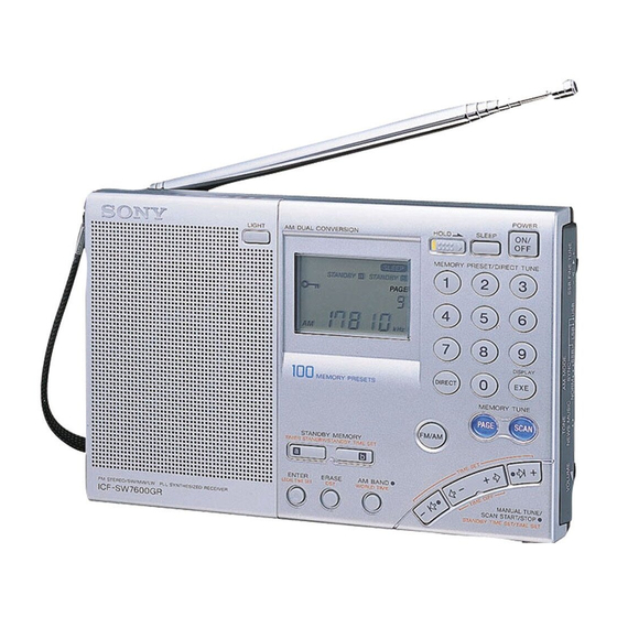
Sony ICF-SW7600GR - Portable Radio Service Manual
Fm stereo/sw/mw/lw pll synthesized receiver
Hide thumbs
Also See for ICF-SW7600GR - Portable Radio:
- Operating instructions manual (242 pages) ,
- Operating instruction (202 pages) ,
- Service manual (26 pages)
Table of Contents
Advertisement
Quick Links
SERVICE MANUAL
Ver 1.0 2001. 03
Sony Corporation
9-873-099-11
2001C1600-1
Audio Entertainment Group
© 2001.3
General Engineering Dept.
ICF-SW7600GR
SPECIFICATIONS
Circuit system
FM: Super heterodyne
AM: Dual conversion super heterodyne
Frequency range
FM: 76–108 MHz
SW: 1 621– 29 999 kHz
MW: 530–1 620 kHz
LW: 150–529 kHz
LINE OUT jack (stereo minijack) × 1
Output
Recording output level approx. 245 mV, output
impedance less than 10 kΩ
i (headphones) jack (stereo minijack) × 1 16 Ω
Approx. 77 mm diameter, 8 Ω × 1
Speaker
Maximum output
380 mW (at 10 % harmonic distortion)
Power requirements
DC 6 V, four R6 (size AA) batteries
External power source
DC IN 6V (except Chinese)
Approx. 190 × 118.8 × 35.3 mm incl. projecting parts
Dimensions
(w/h/d)
Mass
Approx. 536 g
Approx. 608 g (incl. four R6 (size AA) batteries)
Supplied accessories
Carrying case (1)
Compact antenna AN-71 (1)
Wave Handbook (1)
Design and specifications are subject to change without notice.
Canadian Model
Chinese Model
FM STEREO/SW/MW/LW
PLL SYNTHESIZED RECEIVER
US Model
AEP Model
E Model
Tourist Model
Advertisement
Table of Contents

Related Manuals for Sony ICF-SW7600GR - Portable Radio


Summary of Contents for Sony ICF-SW7600GR - Portable Radio
- Page 1 Approx. 608 g (incl. four R6 (size AA) batteries) Supplied accessories Carrying case (1) Compact antenna AN-71 (1) Wave Handbook (1) Design and specifications are subject to change without notice. FM STEREO/SW/MW/LW PLL SYNTHESIZED RECEIVER Sony Corporation 9-873-099-11 2001C1600-1 Audio Entertainment Group © 2001.3 General Engineering Dept.
-
Page 2: Table Of Contents
CRITIQUES POUR LA SÉCURITÉ DE FONCTIONNEMENT. NE COMPONENTS WITH SONY PARTS WHOSE PART NUMBERS REMPLACER CES COMPOSANTS QUE PAR DES PIÈSES SONY APPEAR AS SHOWN IN THIS MANUAL OR IN SUPPLEMENTS DONT LES NUMÉROS SONT DONNÉS DANS CE MANUEL OU PUBLISHED BY SONY. -
Page 3: General
ICF-SW7600GR SECTION 1 GENERAL This section is extracted from instruction manual. Front Rear 1 AM EXT ANT (AM qa SSB FINE TUNE control (26) 6 DC IN 6V ! external antenna) jack (35) (external power input) qs LSB/USB selector (26, 27) jack (10) 2 ATT (attenuator) control qd AM MODE selector (26, 27) - Page 4 ICF-SW7600GR Controls Display 1 TUNE indicator (16, 18) 7 SLEEP indicator (31) 1 SLEEP button (31) 0 Number buttons (15, 16, 22, 23, 24) Appears when a station Appears when the sleep 2 HOLD switch (32) is tuned in. timer is in effect. qa DISPLAY, EXE button 3 DIRECT button (15, 16) 2 Battery indicator (9)
- Page 5 ICF-SW7600GR Setting the Current Time “0:00” flashes in the display when installing the batteries for the first time To set the daylight saving time, press DST to display or when the unit has been reset. Set the clock to the current time. indicator.
-
Page 6: Disassembly
ICF-SW7600GR SECTION 2 DISASSEMBLY Note : Follow the disassembly procedure in the numerical order given. 2-1. CABINET (REAR) 1 Three screws (+BTP 3 × 25) 2 Two screws (+BTP 3 × 25) 4 Cabinet (rear) 3 Four claws SECTION 3 ELECTRICAL ADJUSTMENTS •... - Page 7 ICF-SW7600GR (3) 2nd Local Adjustment (6) Just Tune Adjustment Setting: Setting : ATT switch : OFF ATT switch : OFF TONE switch : MUSIC TONE switch : MUSIC AM MODE switch : NORM (FM RF signal generator) Frequency : 93.025MHz Procedure: Moduration : 22.5kHz...
- Page 8 ICF-SW7600GR Adjustment Location : [MAIN BOARD] — Component Side — FM TRACKING T202 Adjustment (108MHz) 1st IF Adjustment CT101 CT102 Adjustment T104 T105 RV202 JUST TUNE Adjustment RV203 76kHz (MPX) Adjustment IC201 CT202 T101 T102 CT201 2nd LOCAL Adjustment FM TRACKING 0 BEAT Adjustment Adjustment...
-
Page 9: Block Diagram
ICF-SW7600GR SECTION 4 DIAGRAMS 4-1. BLOCK DIAGRAM FM TRACKING FM TRACKING IC201 ANT101 FM/AM FRONT-END (TELESCOPIC) T101 CT101 T102 CT102 IF,DET CF202 CF203 FM ANT FM RF 10.7MHz 10.7MHz Q104 FMLIMIN FEOUT FMIFIN FMIFOUT FMRF RF AMP Q209 Q210 METER METER Q120 CF201... -
Page 10: Main Board (Conductor Side)
ICF-SW7600GR 4-2. PRINTED WIRING BOARD – MAIN BOARD (CONDUCTOR SIDE) – MAIN BOARD (CONDUCTOR SIDE) ANT101 FM/SW TELESCOPIC ANTENNA ANT102 UNPLUGGED MW/LW FERRITE-ROD PLUGGED EXCEPT EA ANTENNA J101 RV201 AM EXT ANT SSB FINE TUNE T106 XF101 T104 C128 CF202 C146 CT102 CF201... -
Page 11: Main Board (Component Side)
ICF-SW7600GR 4-3. PRINTED WIRING BOARD – MAIN BOARD (COMPONENT SIDE) – MAIN BOARD (COMPONENT SIDE) KEY BOARD 1-679-368- (11) Note on Printed Wiring Boards: • X : parts extracted from the component side. • : Through hole. • : Pattern from the side which enables seeing. (The other layers' patterns are not indicated.) Caution: Pattern face side:... -
Page 12: Schematic Diagram - Main Board (1/2)
ICF-SW7600GR 4-4. SCHEMATIC DIAGRAM – MAIN BOARD (1/2) – Note on Schematic Diagram: • All capacitors are in µF unless otherwise noted. pF: µµF • Voltages are taken with a VOM (Input impedance 10 MΩ). 50 WV or less are not indicated except for electrolytics Voltage variations may be noted due to normal produc- and tantalums. -
Page 13: Schematic Diagram - Main Board (2/2)
ICF-SW7600GR 4-5. SCHEMATIC DIAGRAM – MAIN BOARD (2/2) – • Refer to page 16 for IC Block Diagrams. Note on Schematic Diagram: • All capacitors are in µF unless otherwise noted. pF: µµF 50 WV or less are not indicated except for electrolytics and tantalums. -
Page 14: Printed Wiring Board - Key Board
ICF-SW7600GR 4-6. PRINTED WIRING BOARD – KEY BOARD – KEY BOARD KEY BOARD (CONDUCTOR SIDE) (COMPONENT SIDE) S304 POWER S308 S312 SLEEP LIGHT S329 HOLD. S303 S302 S301 LCD1 LIQUID CRYSTAL DISPLAY PANEL S307 S306 S305 D301 (BACK LIGHT) S311 S310 S309 CN382... -
Page 15: Schematic Diagram - Key Board
ICF-SW7600GR 4-7. SCHEMATIC DIAGRAM – KEY BOARD – • Refer to page 16 for IC Pin Function. • WAVEFORM Note on Schematic Diagram: • All capacitors are in µF unless otherwise noted. pF: µµF • Voltages are taken with a VOM (Input impedance 10 MΩ). 50 WV or less are not indicated except for electrolytics Voltage variations may be noted due to normal produc- IC302 wf... -
Page 16: Ic Pin Function Description
ICF-SW7600GR • IC BLOCK DIAGRAMS IC201 CXA1376AS 4-8. IC PIN FUNCTION DESCRIPTION µPD17073GB-564-1A7 (DIGITAL TUNING SYSTEM CONTROL) • IC302 Pin No. Pin Name Description LIGHT Light control signal output MUTING Muting signal output Key source signal output Key source signal output Key source signal output Key source signal output Key source signal output... -
Page 17: Exploded Views
ICF-SW7600GR SECTION 5 EXPLODED VIEWS NOTE: • Abbreviation • -XX, -X mean standardized parts, so they may • The mechanical parts with no reference number : Chinese model have some differences from the original one. in the exploded views are not supplied. CND : Canadian model •... -
Page 18: Chassis Section
ICF-SW7600GR 5-2. CHASSIS SECTION ANT102 SP201 LCD1 Ref. No. Part No. Description Remarks Ref. No. Part No. Description Remarks * 51 A-4440-289-A KEY BOARD, COMPLETE 3-227-396-01 TERMINAL (+), BATTERY 4-910-502-01 CUSHION, ANTENNA 3-227-392-01 CHASSIS 3-227-395-01 PANEL (SIDE) (EXCEPT EA) * 59 3-227-389-01 HOLDER (LCD) 3-227-395-11 PANEL (SIDE) (EA) * 60... -
Page 19: Electrical Parts List
ICF-SW7600GR SECTION 6 ELECTRICAL PARTS LIST NOTE: • Due to standardization, replacements in the • COILS When indicating parts by reference number, uH: µH parts list may be different from the parts please include the board name. specified in the diagrams or the components •... - Page 20 ICF-SW7600GR Ref. No. Part No. Description Remarks Ref. No. Part No. Description Remarks R305 1-216-813-11 METAL CHIP 1/16W R362 1-216-821-11 METAL CHIP 1/16W R363 1-216-821-11 METAL CHIP 1/16W R306 1-216-821-11 METAL CHIP 1/16W R364 1-216-857-11 METAL CHIP 1/16W R307 1-216-821-11 METAL CHIP 1/16W R365 1-216-829-11 METAL CHIP...
- Page 21 ICF-SW7600GR MAIN Ref. No. Part No. Description Remarks Ref. No. Part No. Description Remarks A-4440-288-A MAIN BOARD, COMPLETE (EXCEPT CH, EA) C156 1-162-921-11 CERAMIC CHIP 33PF A-4440-290-A MAIN BOARD, COMPLETE (EA) C157 1-124-589-11 ELECT 47uF A-4440-291-A MAIN BOARD, COMPLETE (CH) C159 1-164-156-11 CERAMIC CHIP 0.1uF...
- Page 22 ICF-SW7600GR MAIN Ref. No. Part No. Description Remarks Ref. No. Part No. Description Remarks C256 1-115-156-11 CERAMIC CHIP D107 8-719-421-40 DIODE MA77 C257 1-115-156-11 CERAMIC CHIP D108 8-719-421-40 DIODE MA77 C258 1-115-156-11 CERAMIC CHIP D109 8-719-002-81 DIODE 1T363 C259 1-126-935-11 ELECT 470uF 20.00% 10V D110...
- Page 23 ICF-SW7600GR MAIN Ref. No. Part No. Description Remarks Ref. No. Part No. Description Remarks Q110 8-729-116-64 TRANSISTOR 2SK508-K51 R125 1-216-825-11 METAL CHIP 2.2K 1/16W Q111 8-729-208-47 TRANSISTOR 2SK210-GR Q112 8-729-423-52 TRANSISTOR 2SC3931-C R126 1-216-825-11 METAL CHIP 2.2K 1/16W R127 1-216-825-11 METAL CHIP 2.2K 1/16W Q113...
- Page 24 ICF-SW7600GR MAIN Ref. No. Part No. Description Remarks Ref. No. Part No. Description Remarks R227 1-216-841-11 METAL CHIP 1/16W < SWITCH > R228 1-216-809-11 METAL CHIP 1/16W R229 1-216-855-11 METAL CHIP 680K 1/16W S101 1-571-850-81 SWITCH, SLIDE (ATT) R230 1-216-841-11 METAL CHIP 1/16W S201 1-786-100-11 SWITCH, SLIDE (AM MODE)
- Page 25 ICF-SW7600GR MEMO...
- Page 26 ICF-SW7600GR REVISION HISTORY Clicking the version allows you to jump to the revised page. Also, clicking the version at the upper right on the revised page allows you to jump to the next revised page. Ver. Date Description of Revision 2001.03...