Kyocera FS-1050 - B/W Laser Printer Service Manual
Service manual
Hide thumbs
Also See for FS-1050 - B/W Laser Printer:
- Installation manual (32 pages) ,
- Service manual (11 pages) ,
- User manual (154 pages)
Table of Contents
Advertisement
Quick Links
Advertisement
Chapters
Table of Contents
Troubleshooting

Subscribe to Our Youtube Channel
Related Manuals for Kyocera FS-1050 - B/W Laser Printer


Summary of Contents for Kyocera FS-1050 - B/W Laser Printer
-
Page 1: Service Manual
Laser printer SERVICE MANUAL Published in Dec. ’01... - Page 2 Revision history Version Date Replaced pages Remarks 5-Dec-2001...
-
Page 3: Safety Precautions
Safety precautions This booklet provides safety warnings and precautions for our service personnel to ensure the safety of their customers, their machines as well as themselves during maintenance activities. Service personnel are advised to read this booklet carefully to familiarize themselves with the warnings and precautions described here before engaging in maintenance activities. - Page 4 Safety warnings and precautions Various symbols are used to protect our service personnel and customers from physical danger and to prevent damage to their property. These symbols are described below: DANGER: High risk of serious bodily injury or death may result from insufficient attention to or incorrect compliance with warning messages using this symbol.
-
Page 5: Installation Precautions
1. Installation Precautions WARNING • Do not use a power supply with a voltage other than that specified. Avoid multiple connections to one outlet: they may cause fire or electric shock. When using an extension cable, always check that it is adequate for the rated current..................... •... - Page 6 2. Precautions for Maintenance WARNING • Always remove the power plug from the wall outlet before starting machine disassembly....• Always follow the procedures for maintenance described in the service manual and other related brochures............................• Under no circumstances attempt to bypass or disable safety features including safety mechanisms and protective circuits.
- Page 7 • Do not pull on the AC power cord or connector wires on high-voltage components when removing them; always hold the plug itself....................... • Do not route the power cable where it may be stood on or trapped. If necessary, protect it with a cable cover or other appropriate item.
-
Page 8: Table Of Contents
Contents Chapter 1 1-1 Printer specifications ............................1-3 1-2 Names of parts ..............................1-6 1-3 Safety information ............................1-7 1-4 Environmental requirements .......................... 1-10 1-5 About the toner container ..........................1-14 Chapter 2 2-1 Unpacking ................................ 2-3 2-2 Installing the printer ............................2-4 2-3 Using the operator panel .......................... - Page 9 P r o d u c t I n f o r m a t i o n Chapter 1...
- Page 10 Chapter 1 Contents 1-1 Printer specifications ........................1-3 1-1-1 Specifications ..........................1-3 (1) Engine ..........................1-3 (2) Controller ..........................1-4 (3) Weight and dimensions ....................... 1-4 (4) Power requirements ......................1-5 (5) Environmental requirements ....................1-5 1-2 Names of parts ..........................1-6 1-2-1 Name of parts ..........................
-
Page 11: Printer Specifications
15 pages/min. (Letter) Resolution (dpi) Fast 1200 mode (1800 horizontal/600 vertical) 600 horizontal/600 vertical KIR (Kyocera Image Refinement) Smoothing First print (A4 or letter, 23 °C), 22 seconds or less depends on input data Warm-up time at 23 °C... -
Page 12: Controller
(2) Controller Item Specification PowerPC405/200MHz System ROM 4 MB Flash DIMM Font ROM 2 MB (16 M bit × 1) Optional font ROM (Dip socket) 1 MB (Optional KPDL2 Upgrade kit) Main (Video) RAM 16 MB (Standard-equipped on main board) Expanding RAM (DIMM slot ×... -
Page 13: Power Requirements
(4) Power requirements Item Specification Item Voltage/current requirement 220 to 240 V AC ±10 %, 50/60 Hz ±2 %/3.8 A Watts Normal operation: 265 W Maximum: 818 W Standby: 13 W Sleeping: 5 W (5) Environmental requirements Item Specification Item Operating temperature and 10 to 32.5 °C (50 to 90.5 °F), 20 to 80 %RH humidity... -
Page 14: Names Of Parts
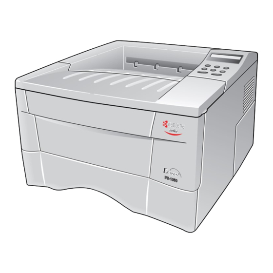
1-2 Names of parts 1-2-1 Name of parts 1 Top cover 8 MP tray 2 Face-down output tray 9 Option card slot 3 Face-up output tray 0 Parallel interface connector 4 Side cover ! USB interface connector 5 Operator panel @ Power switch 6 Front cover # AC inlet... -
Page 15: Safety Information
1-3 Safety information 1-3-1 Safety information (1) Laser safety This printer is certified as a Class 1 laser product under the U.S. Department of Health and Human Services (DHHS) Radiation Performance Standard according to Radiation Control for Health and Safety Act of 1968. This means that the printer does not produce hazardous laser radiation. Since radiation emitted inside the printer is completely confined within protective housings and external covers, the laser beam cannot escape from the printer during any phase of user operation. - Page 16 WARNING Use of controls or adjustments or performance of procedures other than those specified herein may result in hazardous radiation exposure. Label on the scanner unit (Inside the printer) Label on the left cover rear side Label on the fuser unit Figure 1-3-1 Caution labels FS-1050...
-
Page 17: Cdrh Regulations (U.s.a.)
(4) CDRH regulations (U.S.A.) The Center of Devices and Radiological Health (CDRH) of the U.S. Food and Drug Administration implemented regulations for laser products on August 2, 1976. These regulations apply to laser products manufactured after August 1, 1976. Compliance is mandatory for products marketed in the United States. -
Page 18: Environmental Requirements
1-4 Environmental requirements 1-4-1 Environmental conditions The Environmental requirements section on page 1-5 should be observed to ensure the optimum operation of the printer. The use of the printer in a location which does not satisfy the requirements may result in troubles and risk shortening its service life. The printer will work best if it is installed in a location that is: •... -
Page 19: Clearance
(1) Clearance Allow the necessary minimum clearance on all sides of the printer as diagrammed below. Figure 1-4-2 Clearances Ref. Clearance Dimensions Left 25 cm (9-7/8 inches) Front 50 cm (19-11/16 inches) Right 25 cm (9-7/8 inches) Back 40 cm (15-3/4 inches) Above 30 cm (11-13/16 inches) FS-1050... -
Page 20: Places To Avoid
(2) Places to avoid Avoid installing the printer in locations exposed to: • Direct drafts of hot or cold air. • Direct drafts of outside air. (Avoid locations next to outside doors.) • Sudden temperature or humidity changes. • Any source of high heat, such as a radiator or stove. •... -
Page 21: Removing The Printer
(4) Removing the printer Observe the following precautions in removal and transportation of the printer. • Be sure to repack the printer in its original carton. • Do not leave the printer, toner container, process unit and other printer modules inside a vehicle if the outdoor temperature is more than 25 °C. -
Page 22: About The Toner Container
Kyocera’s proprietary toner, Kyocera do not recommend to use any refilled toner containers that may be available commercially. This is because Kyocera have no means of control over how such refilled toner could affect the print quality and the reliability of the printer. -
Page 23: Toner Container Storage
(2) Toner container storage The toner contained in the container is susceptible to temperature and humidity. To ensure the high print quality, store the toner container in a place that satisfies the following environmental conditions: Temperature: -20 to 40 °C (-4 to 104 °F) Humidity: 15 to 90 % RH NOTE... - Page 24 I n s t a l l a t i o n / O p e r a t i o n Chapter 2...
- Page 25 Chapter 2 Contents 2-1 Unpacking ............................2-3 2-1-1 Unpacking and inspection ......................2-3 2-2 Installing the printer ........................2-4 2-2-1 Installing the toner container ..................... 2-4 2-2-2 Expanding memory ........................2-8 (1) Minimum memory requirements ..................2-8 (2) DIMM specifications ......................2-8 (3) Notes on handling DIMM .....................
-
Page 26: Unpacking
Carefully remove the printer. Toner container (TK-17) Cleaning cloth Printer Installation guide Kyocera Mita digital library Power cord CD-ROM Figure 2-1-1 Unpacking (1) Remove the tape on the rear side of the printer, and remove the two spacers and the printed notice from the paper cassette. -
Page 27: Installing The Printer
2-2 Installing the printer Installing the printer requires several steps. Proceed as follows in sequence. If the option paper feeder is used with the printer, begin installation with connecting the printer and the paper feeder. For details, refer to the optional Paper feeder’s Service Manual. 2-2-1 Installing the toner container 1. - Page 28 3. Take the toner container 2 from the bag. Hold it with the protective seal 3 (orange-colored) facing up. Shake the toner container 2 horizontally at least five times. This ensures that the toner is evenly distributed inside. Figure 2-2-2 Shaking the toner container 4.
- Page 29 5. Install the toner container 2 into the printer. 6. Push firmly on the top of the toner container 2 at the positions marked [PUSH HERE]. Figure 2-2-4 Installing the toner container FS-1050...
- Page 30 7. Push the lock lever #1 1 to the lock position. 8. Close the top cover 4. Figure- 2-2-5 Locking the toner container NOTE The printer is shipped from the factory with no toner supplied in its developer (Process unit). When the printer is first switched on after the toner container is installed in the manner above, there will be a delay of several minutes before the printer gets ready to print a job.
-
Page 31: Expanding Memory
2-2-2 Expanding memory The FS-1050 printer comes standard equipped with 16 MB of main memory on the main board. Printer memory can be expanded to up to the maximum 144 MB (16 + 128 MB). (1) Minimum memory requirements Refer to the table below for minimum memory requirements in various environments. Resolution Printing environment (Emulation) 300 dpi... -
Page 32: Notes On Handling Dimm
(3) Notes on handling DIMM Before proceeding to install DIMM, read the following notes for handling the main board and DIMMs: • Protect the electronics by taking these precautions: • Before touching a DIMM, touch a water pipe or other large metal object to discharge yourself of static electricity. -
Page 33: Installing The Dimm
(4) Installing the DIMM The main board of the printer is equipped with one socket for memory expansion. Expansion memory is available in the form of DIMM (Dual In-line Memory Module). CAUTION Take precautions that no foreign substances such as metal chips or liquid get inside the printer during the installation process. -
Page 34: Testing The Expansion Memory
Open the clips 2 on both ends of the DIMM socket 3. Insert the DIMM 4 into the DIMM socket 3 so that the notches on the DIMM align with the corresponding protrusions in the slot. Close the clips 5 on the DIMM slot to secure the DIMM. Step 1 Step 2 Figure 2-2-8 Inserting the DIMM... -
Page 35: Installing The Memory Card (Compactflash)
(5) Installing the memory card (CompactFlash) The main board of the printer is equipped with one slot for memory card. CAUTION Take precautions that no foreign substances such as metal chips or liquid get inside the printer during the installation process. Operation of the printer during the presence of a foreign substance may lead to fire or electric shock. - Page 36 Insert the memory card 4 in the slot. Insert as shown in the figure. Push it in all the way. Close and secure the slot cover (or network interface card or the serial Interface board) . Figure 2-2-10 installing the memory card FS-1050 2-13...
-
Page 37: Installing The Network Interface Card
(6) Installing the network interface card If the serial interface board kit is installed, remove it to use the network interface card. CAUTION Take precautions that no foreign substances such as metal chips or liquid get inside the printer during the installation process. Operation of the printer during the presence of a foreign substance may lead to fire or electric shock. -
Page 38: Using The Operator Panel
2-3 Using the operator panel This section provides explanation on how to use the printer’s operator panel for basic operation. For details, refer to the printer’s User’s Manual. 2-3-1 Operator panel The printer’s operator panel has the following LED indicators, keys, and LCD message display. Note that adjustments to the printer parameters made using these keys may be overridden by those made from within the application software. -
Page 39: Keys
Indicator Condition Description 3 ATTENTION Flashing Indicates that paper has run out, that memory is indicator insufficient, that toner is low, or other warning messages. Indicates common errors (such as controller errors), when mechanical maintenance is needed or indicates a problem that requires a call to the service center. -
Page 40: Lcd Message Display
Function Used to access desired items or input numeric values. In some control procedures, the < and > keys are used to access or exit submenu items. Used to access desired items or input numeric values. In some control procedures, the < and > keys are used to access or exit submenu items. 9 <... -
Page 41: Interface Indicator
Interface indicator The LCD message display also shows the interface that is currently used in the from of the following abbreviations: Message Meaning Standard bidirectional parallel interface Standard USB interface Optional serial interface (RS-232C) Optional network interface card No interface is currently used. Each interface has a time-out time of 30 seconds during which the other interface should wait to receive a print job. -
Page 42: Menu Selection System
2-3-2 Menu selection system The MENU key on the operator panel allows you to use the menu selection system to set or change the printer environment such as the paper source, emulation, etc. Settings can be made when Ready is indicated on the printer message display. The printer obeys the most recently received printer settings sent from the application software, or from the printer driver, which take priority over operator panel settings. - Page 43 >Font Select > Emulation > Option PCL 6 > I000 >Code set ISO-6 ASCII >Courier Emulation > Regular KPDL >Courier >Print KPDL errs Dark >Letter Gothic >Print KPDL errs Regular >Letter Gothic Emulation > Dark KPDL (AUTO) >Size >Alt. Emulation 012.00 point(s) PCL 6 >Pitch...
- Page 44 Print Quality > Paper Handling > >KIR Mode >MP Tray Mode Cassette >KIR Mode >MP Tray Mode First >Ecoprint Mode >MP Tray Size >Ecoprint Mode >MP Tray Type Plain >Resolution >Cassette Size Fast 1200 mode >Resolution >Cassette Size 300 dpi Custom >Resolution >>Unit...
- Page 45 Others > >MSG language English >Form Feed Time Out 030sec. >Sleep Timer > 015 min. >>Sleep Mode >>Sleep Mode >Print HEX-DUMP >Printer Reset >Resource prot. >Resource prot. Permanent >Resource prot. Perm / Temp >Auto Continue Mode >Auto Continue > Mode >>Auto Continue Timer 030sec.
-
Page 46: Maintenance/Adjustments
Maintenance/Adjustments Chapter 3... - Page 47 Chapter 3 Contents 3-1 Maintenance/Adjustments ......................3-3 3-1-1 Life expectancy of modules ....................... 3-3 3-1-2 Toner container .......................... 3-4 (1) When to replace the toner container ................... 3-4 (2) Notes on changing toner container ..................3-4 (3) Toner container replacement ....................3-5 (4) Toner saver mode (EcoPrint) ....................
-
Page 48: Maintenance/Adjustments
3-1 Maintenance/Adjustments 3-1-1 Life expectancy of modules The table below shows the nominal life expectancy for modules. Detailed part information for each module (except toner container) can be found in Parts Catalog. Table 3-1-1 Life expectancy of modules Module Nominal life (pages) Remarks TK-17 Toner container... -
Page 49: Toner Container
3-1-2 Toner container Assuming an average toner coverage of 5 % with EcoPrint mode turned off, the toner container will need replacing approximately once every 6,000 printed pages. Table 3-1-2 Toner container Life in pages TK-17 6,000 Based on letter or A4 size paper; average print density of 5 %. NOTE In the case of a new printer in which a toner kit has been installed for the first time, the number of copies that can be printed will be approximately 3,000. -
Page 50: Toner Container Replacement
(3) Toner container replacement To replace the toner container, open the top cover. Pull lock lever #1 1 to the release [UNLOCK] position, then pull lock lever #2 2 to the release (right) position. Figure 3-1-1 Releasing Lock levers #1 and #2 Gently remove the old toner container 3. -
Page 51: Toner Saver Mode (Ecoprint)
Put it in the supplied plastic bag 4 and dispose of it. Figure 3-1-3 Disposal of the old toner container NOTE Although the toner container is made from non-harmful, flammable material, be sure to dispose of it according to laws and regulations. Proceed with the instructions provided in chapter 2, Installing the toner container on page 2-4 to complete installation of the new toner container. -
Page 52: Cleaning The Printer
3-1-3 Cleaning the printer To avoid print quality problems, the following printer parts must be cleaned with every toner container replacement. To clean the printer, first, remove the process unit from the printer. Open the top cover 1 and front cover 2. Lift the process unit 3 together with the toner container out of the printer. -
Page 53: Cleaning The Registration Roller
(1) Cleaning the registration roller Use the supplied wiper cloth 1 to clean dust and dirt away from the registration roller 2 (metal). Figure 3-1-5 Cleaning the registration roller (2) Cleaning the main charger wire Slide the charger cleaner knob (green colored) back and forth 2 to 3 times, then return it to its [CLEANER HOME POSITION]. -
Page 54: Updating The Firmware
(CompactFlash). (1) Firmware program data format Kyocera supplies the following types of data for updating firmware of the different purposes: • System firmware The data to be downloaded are supplied in the following format: System firmware file name example A93K8000.bcmp... -
Page 55: Downloading The Firmware From The Parallel Interface
(2) Downloading the firmware from the parallel interface This section explains how to download firmware data from the parallel interface. The printer system can automatically recognize whether the data to be overwritten is for controller firmware. CAUTION Downloading the firmware takes several minutes. Do not turn power off during downloading. - Page 56 4 Supervisor mode. The parallel interface is waiting for the firmware data. 5 Receiving the firmware data. 6 The system DIMM or flash ROM is overwritten with the new firmware data. 7 Firmware downloading is finished. (When more than one data are down loaded, the data display can be changed by pressing any key.) 8 Turn power switch off and on.
-
Page 57: Downloading The Firmware From The Memory Card
(3) Downloading the firmware from the memory card To download data written in a memory card (CompactFlash) to the printer, proceed as explained in this section. CAUTION Downloading firmware takes several minutes. Do not turn power off during downloading. If downloading is interrupted by an accidental power failure, etc., the system DIMM may have to be replaced. - Page 58 5 Data are transferred to the RAM on the main board. 6 The system DIMM or Flash ROM is overwritten with the new firmware data. 7 Firmware download is finished. (When more than one data are down loaded, the data display can be changed by pressing any key.
-
Page 59: Downloading Errors
(4) Downloading errors The following messages are indicated on the message display when an error occurred during downloading the firmware data. Error message Description Corrective action Deficit of the file header Obtain the correct firmware. download header Deficit of the data header error [##] File checksum error ##: Error code 20 to 26. - Page 60 O p e r a t i o n O v e r v i e w Chapter 4...
- Page 61 Chapter 4 Contents 4-1 Electrophotographic system ......................4-3 4-1-1 Electrophotographic cycle ......................4-3 Process unit mechanism ......................4-4 (1) Main charging ........................4-5 Photo conductive drum ......................4-5 Charging the drum ........................4-6 (2) Exposure ..........................4-7 Laser scanner unit ........................4-8 Drum surface potential ......................
-
Page 62: Electrophotographic System
4-1 Electrophotographic system Electrophotography is the technology used in laser printing which transfer data representing texts or graphics objects into a visible image which is developed on the photosensitive drum, finally fusing on paper, using light beam generated by a laser diode. This section provides technical details on the printer’s electrophotography system. -
Page 63: Process Unit Mechanism
Process unit mechanism Driving power train A For drum (From main unit) B For toner container, developing roller, etc. (From main unit) C For main unit (Transfer roller) D For toner container ¤ & ⁄ ‹ 1 Main charger unit 9 Gear Z18-Z35H &... -
Page 64: Main Charging
(1) Main charging Photo conductive drum The durable layer of organic photoconductor (OPC) is coated over the aluminum cylinder base. The OPC tend to reduce its own electrical conductance when exposed to light. After a cyclic process of charging, exposure, and development, the electrostatic image is constituted over the OPC layer. Since the OPC is materialized by resin, it is susceptible to damage caused by sharp edges such as a screwdriver, etc., resulting in a print quality problem. -
Page 65: Charging The Drum
Charging the drum The following shows a simplified diagram of the electrophotographic components in relation to the engine system. Charging the drum is done by the main charger unit A. High voltage board Engine board Bias board MHVDR CN2-A4 YC12-5 YC-M Main charging output Zener... -
Page 66: Exposure
(2) Exposure The charged surface of the drum A is then scanned by the laser beam from the laser scanner unit Figure 4-1-5 Exposure The laser beam (780 nm wavelength) beam is dispersed as the polygon motor (polygon mirrors) revolves to reflect the laser beam over the drum. Various lenses and mirror are housed in the scanner unit, adjust the diameter of the laser beam, and focalize it at the drum surface. -
Page 67: Laser Scanner Unit
Laser scanner unit Diversion mirror Figure 4-1-6 Laser scanner unit Name Description 1 Laser diode Emits diffused, visible laser. 2 Cylindrical lens Compensates the vertical angle at which the laser beam hits a polygon mirror segment. 3 Polygon mirror (motor) Has six mirror segments around its hexagonal circumference; each mirror corresponding to one scanned line width on the drum when laser beam scans on it. -
Page 68: Drum Surface Potential
Drum surface potential The laser beam is continually switched on and off depending on the print data. It is on for a black (exposed) dot and off for a white (blank) dot. Since the drum surface is evenly charged, whenever it is illuminated by the laser beam, the electrical resistance of the photoconductor is reduced and the potential on the photoconductor is also lowered. -
Page 69: Development
(3) Development The latent image constituted on the drum is developed into a visible image. The developing roller A contains a 3-pole (S-N-S) magnet core B and an aluminum cylinder rotating around the magnet core B. Toner attracts to the developing roller A since it is powdery ink made of black resin bound to iron particles. -
Page 70: Transfer
(4) Transfer The image developed by toner on the drum A is transferred onto the paper because of the electrical attraction between the toner itself and the transfer roller B. The transfer roller is negatively biased so that the positively charged toner is attracted onto the paper while it is pinched by the drum and the transfer roller. -
Page 71: Fusing
(5) Fusing The toner on the paper is molten and pressed into the paper as it passes between the heat roller A and the press roller B in the fuser unit. Figure 4-1-10 Fusing The heat roller has a halogen lamp inside which continuously turns on and off by the thermistor to maintain the constant temperature onto the heat roller surface. -
Page 72: Fuser Unit Mechanism
Fuser unit mechanism 1 Heat roller 5 Heat gear Z33 9 Separator(s) 2 Idle gear Z34 6 Press roller 0 Thermistor 3 Exit gear Z23 7 Heater lamp [500±25 W] ! Exit pulley(s) 4 Idle gear Z18 8 Thermal cutout @ Lower exit roller Figure 4-1-11 Fuser unit mechanism FS-1050... -
Page 73: Cleaning
(6) Cleaning After the transferring process, the drum needs to be physically cleaned of toner which is residual after the development process. The cleaning blade A is constantly pressed against the drum B and scrapes the residual toner off to the sweep roller C. The waste toner is collected at the output end of the sweep roller C and sent back to the toner container, into the waste toner reservoir D. -
Page 74: Paper Feeding System
4-2 Paper feeding system The paper feeding system picks up paper from the cassette, MP tray, or if installed, the paper feeder PF-17, feeds it in the printer, and delivers in the output tray. Paper is fed at the precise timing in synchronization with data processing. -
Page 75: Paper Feed Control
4-2-1 Paper feed control The following diagram shows interconnectivity of the feeding system components including the sensors and rollers. The engine board provides the signals in conjunction with the electrophotography process that is driven by the main board. Power train Toner container TK-17 Process unit... -
Page 76: Paper Feeding Mechanism
Paper feeding mechanism Driving power train A For process unit; drum (From main unit) B For process unit; toner container, developing roller etc. (From main unit) C From process unit; drum (To transfer roller) & 1 Main motor (gear) 2 Registration clutch 3 MP feed clutch 4 Feed clutch 5 MP feed roller... -
Page 77: Electrical Control System
4-3 Electrical control system 4-3-1 Electrical parts layout D 5 ^ & ( 1 Main board (KP-888) 6 Bias board (KP-884) @ MP paper sensor 2 Engine board (KP-882) E Cassette switch # Toner sensor 3 Power supply board F Registration sensor $ Waste toner sensor A Power switch G Paper sensor... -
Page 78: Operation Of Circuit Boards
4-3-2 Operation of circuit boards (1) Main board YC03 USB I/F Operator panel I/F Digital Transistor USBINT YC08 USBDP FPRSTN USBDN FPCLK FPDIR VBUL FPDAT Digital Transistor YC02 EBA22, EBA10-1 EDB31-16 YC07 APC I/F Option EBCSN2, EBCSN3 Memory OUTPEN EBOEN1, EBWEN1 card LONB CDWAITN, CDET1-2... -
Page 79: Engine Board
(2) Engine board Engine board (KP-882) Optional paper feeder Main board (KP-888) RSTIN PLGCLK PFMDRN Reset IC RSTN PFSEN, PFPFPER, PFCLK MOTORN MRDYN PLGDRN Main motor PLGRDYN EEDIO Laser scanner unit EEPROM EESCK Feed clutch Cassette SWIN switch RESIT Regist- ration PAPERN FEDDRN... -
Page 80: Eraser Lamp Control Circuit
Eraser lamp control circuit The CPU (U01) turns pin #23 (ERASERN) of U01 to H level, transistors (Q16 and Q14) turns on consequently, and the 24 V DC given at pin #1 of connector YC05 applies to the eraser lamps. The eraser lamps thus illuminate as the current flows through the eraser lamp, the pin #2 of connector YC05, resistors (R75/R76, and R77/R78), and the ground. - Page 81 Heater lamp control circuit Activation of the heater lamp is dominated by the HEAT signal which is derived by the engine CPU (U01) at its pin #1. When its level is high, transistor QA03-a turns on, photo-triac PC2 and triac TRC1 turn on simultaneously, and the heater lamp is applied with the primary AC voltage in turn.
- Page 82 The AC power for the heater is applied in one of the five variations of the zero cross switchings as shown in Figure 4-3-6. Each variation is constituted with the unit of ten positive and negative envelops in five cycles, as obtained by varying the duration during which TRC1 turns on. The heater lamp is energized while TRC1 is kept on;...
- Page 83 Heater lamp turn-on pattern in 1 cycle (10 half waves) AC wave Variation No.1 (Duty 100 %) Zero − cross point Conductivity staus of Triac (TRC1) Variation No.2 (Duty 80 %) − Variation No.3 (Duty 60 %) − Variation No.4 (Duty 40 %) −...
-
Page 84: Polygon Motor Control Circuit
Polygon motor control circuit The main controller board supplies the 1700.8 Hz clock pulse (PLGCLK) via the engine board to the PLL control IC (IC1) for the polygon motor. To begin printing, the engine CPU U01 turns PLGDR to H level, the PLL control IC (IC1) starts to revolve the polygon motor so that the revolution is 17,008 rpm which depends on the PLGCLK clock pulse. -
Page 85: Power Supply Board
(3) Power supply board The power supply board provides the AC power input and DC power and outputs. The high voltage bias generator circuit is mounted on a separate board. A simplified schematic diagram is shown below. Power supply unit Power Current switch... -
Page 86: Bias Board
(4) Bias board The bias board contains the developing bias output circuit, registration sensor, paper empty sensor, and the cassette switch. It also provides a liaison connection to the high voltage board, power supply, and the toner sensor. Bias board (KP-884) +5 V Engine board Toner... -
Page 87: High Voltage Board
(5) High voltage board The high voltage board contains the high voltage output circuit, interlock switch circuit as well as providing a liaison connection with the power supply board, bias board, and the engine board. High voltage board High voltage output circuit Engine board Main Bias board... -
Page 88: Interlock Switch
Interlock switch The interlock switch is located on the high voltage board and opened and closed in conjunction with the front cover or the top cover via the interlock lever. This switch connects and disconnects the +24 V DC power supply line. If the front cover or the top cover is open, the interlock switch is open, and the +24 V DC to the high voltage output circuit, bias board, engine board, and the power supply board is disconnected, deactivating the high voltage output, laser output, main motor output for safety. - Page 89 D i s a s s e m b l y Chapter 5...
- Page 90 Chapter 5 Contents 5-1 General instructions ........................5-3 5-1-1 Screw/hardware ......................... 5-3 5-1-2 Before starting disassembly ...................... 5-3 5-2 Disassembly ............................. 5-4 5-2-1 Removing the process unit ......................5-4 5-2-2 Removing the principal outer covers ..................5-5 (1) Removing the top cover/face-down output tray ..............5-5 (2) Removing the right cover ....................
-
Page 91: General Instructions
5-1 General instructions This chapter provides procedures for removal and replacement of the field replacement components. For other components not explained in this chapter, the diagrams in the Parts Catalog attached with this manual will help locate the component. When replacing of a component, reverse the procedure for the removal procedure explained in this chapter. -
Page 92: Disassembly
5-2 Disassembly Before proceeding, remove the paper cassette and the optional paper feeder, if installed. 5-2-1 Removing the process unit 1. Open the top cover 1. 2. Open the front cover 2. 3. Lift the process unit 3 together with the toner container out of the printer. Figure 5-2-1 Removing the process unit CAUTIONS After removing the process unit, seal it in the protective bag and place it on flat... -
Page 93: Removing The Principal Outer Covers
5-2-2 Removing the principal outer covers (1) Removing the top cover/face-down output tray 1. Open the top cover 1. 2. Remove two screws 2. 3. Remove one connector 3. 4. Remove the top cover/face-down output tray 4. Figure 5-2-2 Removing the top cover/face-down output tray FS-1050... -
Page 94: Removing The Right Cover
(2) Removing the right cover 1. Remove one screw 1. 2. Remove the side cover 2. 2. Unlatch the six snaps 3 and one hook hole 4 on the chassis, remove the right cover 5. Figure 5-2-3 Removing the right cover (3) Removing the left cover 1. -
Page 95: Removing The Feed Roller
5-2-3 Removing the feed roller CAUTION When refit the feed roller, fit the D-cut shaft into the D-shape hole of the feed roller. 1. Remove the paper cassette and the process unit. (See page 5-4) 2. Stand the machine the front side up. 3. -
Page 96: Removing The Mp Tray Feed Roller
5-2-4 Removing the MP tray feed roller 1. Remove the engine board. (See page 5-11) 2. Remove one screw 1. 3. Remove the grounding plate 2. 4. Remove one stop ring 3. 5. Remove the MP feed clutch 4. Figure 5-2-6 Removing the MP feed clutch FS-1050... - Page 97 6. Remove one screw 5. 7. Remove the toner sensor 6 and spring 7. 8. Remove two screws 8. 9. While pressing the latch 9 by using the driver and then remove the MP feed unit 0. Figure 5-2-7 Removing the MP feed unit 10.
-
Page 98: Removing The Transfer Roller
5-2-5 Removing the transfer roller CAUTION Do not touch the transfer roller (sponge) surface. Oil and dust (particles of paper, etc.) on the transfer roller can significantly deteriorate the print quality (white spots, etc.). When refitting the bushes and springs, make sure to refit the black colored bush and spring on the left side. -
Page 99: Removing The Principal Circuit Boards
5-2-6 Removing the principal circuit boards (1) Removing the engine board 1. Remove the top cover/face-down output tray and right cover (See pages 5-5 and 5-6). 2. Remove all (ten) connectors from the engine board 1. 3. Remove three screws 2. 4. -
Page 100: Removing The Main Board
(2) Removing the main board 1. Remove the process unit (See page 5-4). 2. Remove the top/face-down output tray and right cover (See pages 5-4 and 5-5). 3. Remove two connectors 1 from main board 2. 4. Remove six screws 3. 5. - Page 101 6. Remove two screws 5 at the back of the main board 2. 7. Remove three screws 6 from the parallel interface connector 7 and USB connector 8. 8. Remove the main board 2. Figure 5-2-12 Removing the main board FS-1050 5-13...
-
Page 102: Removing The Power Supply Board And High Voltage Board
(3) Removing the power supply board and high voltage board 1. Remove the process unit (See page 5-4). 2. Remove the top cover/face-down output tray and left cover (See pages 5-5 and 5-6). 3. Remove three connectors 1 from the power supply board 2. 4. -
Page 103: Removing The Bias Board
(4) Removing the bias board 1. Remove the cassette and process unit (See page 5-4). 2. Remove the top cover/face-down output tray and left cover (See pages 5-5 and 5-6). 3. Remove the power supply board and high voltage board (See the previous page). 4. -
Page 104: Removing The Main Motor And Drive Unit
5-2-7 Removing the main motor and drive unit 1. Remove the cassette and process unit (See page 5-4). 2. Remove the top cover/face-down output tray and right cover (See pages 5-5 and 5-6). 3. Remove three connectors 1 from the main motor 2. 4. - Page 105 6. Remove the engine board (See page 5-11). 7. Remove wires from wire saddles 4 on the cord cover 5. 8. Remove one screw 6. 9. Remove the cord cover 5. 5-2-16 Removing the cord cover FS-1050 5-17...
- Page 106 10. Remove one screw 6. 11. Remove the grounding plate 7. 12. Remove three stop rings 8. 13. Remove MP feed clutch 9, feed clutch 0, and registration clutch !. Figure 5-2-17 Removing the clutches FS-1050 5-18...
- Page 107 14. Remove the four screws @. 15. Remove the drive unit #. Figure 5-2-18 Removing the drive unit FS-1050 5-19...
-
Page 108: Removing And Splitting The Fuser Unit
5-2-8 Removing and splitting the fuser unit WARNING The fuser unit is hot after the printer was running. Wait until it cools down. CAUTION When refitting the fuser unit, make sure the fuser unit gear and the printer’s drive gear are properly meshed with each other. For this, rotate the main motor several turns before fixing screws. - Page 109 7. Remove two screws 5. 8. Open and split the fuser unit 4. Figure 5-2-20 Splitting the fuser unit FS-1050 5-21...
-
Page 110: Removing The Separators
(1) Removing the separators WARNING The separation claws are extremely hot immediately after the printer was running. Allow substantial period of time until it cools down. 1. Remove and split the fuser unit (See page 5-20). 2. Loosen the stopper screws 1. 3. -
Page 111: Removing The Heater Lamp
(2) Removing the heater lamp WARNING The heater lamp is extremely hot immediately after the printer was running. Allow substantial period of time until it cools down. Also, the heater lamp is fragile: Handle it with great care. CAUTION The heater lamps are fragile. Use extreme care when handling not to drop or break. -
Page 112: Removing The Heat Roller
(3) Removing the heat roller WARNING The heat roller is extremely hot immediately after the printer was running. Allow substantial period of time until it cools down. 1. Remove and split the fuser unit (See page 5-20). 2. Remove the heater lamp (See previous page). 3. - Page 113 3. Remove the heat gear Z33 4, heat R bush 2, and heat L bush 3 from the heat roller 5. Figure 5-2-24 Removing the heat roller FS-1050 5-25...
-
Page 114: Removing The Thermistor
(4) Removing the thermistor 1. Remove and split the fuser unit (See page 5-20). 2. Remove the heater lamp (See page 5-23). 3. Remove the heat roller (See page 5-24). 4. Remove one screw 1. 5. Remove the thermistor 2. Figure 5-2-25 Removing the thermistor FS-1050 5-26... -
Page 115: Removing The Thermal Cutout
(5) Removing the thermal cutout CAUTION Do not bend the terminals of the thermal cutout. 1. Remove and split the fuser unit (See page 5-20). 2. Remove the heater lamp (See page 5-23). 3. Remove the heat roller (See page 5-24). 4. -
Page 116: Removing The Press Roller
(6) Removing the press roller WARNING The press roller is extremely hot immediately after the printer was running. Allow substantial period of time until it cools down. 1. Remove and split the fuser unit (See page 5-20). 2. Remove the press roller 1 from the fuser unit 2. Figure 5-2-27 Removing the press roller FS-1050 5-28... -
Page 117: Removing The Laser Scanner Unit And The Eraser Lamp
5-2-9 Removing the laser scanner unit and the eraser lamp 1. Remove the process unit (See page 5-4). 2. Remove the top cover/face-down output tray, right cover, and the left cover (See pages 5-5 and 5-6). 3. Remove four connectors 1. 4. - Page 118 5. Remove three screws 6. 6. Remove one connector 7 from the laser scanner unit 8. 7. Remove the laser scanner unit 8. Figure 5-2-27 Removing the laser scanner unit FS-1050 5-30...
- Page 119 8. Remove the eraser lamp 9. 5-2-28 Removing the eraser lamp FS-1050 5-31...
-
Page 120: Removing The Main Charger Unit
5-2-10 Removing the main charger unit 1. Remove the process unit from the printer (See page 5-4). 2. Unlatch the three snaps 1, and remove the main charger cap 2. 3. Draw the main charger unit 3 in the direction of arrow A, then pull it out in the direction of arrow B. -
Page 121: Troubleshooting
T r o u b l e s h o o t i n g Chapter 6... - Page 122 Chapter 6 Contents 6-1 Troubleshooting ..........................6-3 6-1-1 General error handling ....................... 6-3 (1) Maintenance messages ...................... 6-3 (2) Error messages ........................6-5 6-1-2 Diagnostic (Service error messages) ..................6-7 (1) Call service 7980 - Waste toner full [Total page count less than 100,000 pages of printing] ..6-7 (2) Call service 7990 - Waste toner full [Total page count more than 100,000 pages of printing] ..
-
Page 123: Troubleshooting
6-1 Troubleshooting 6-1-1 General error handling (1) Maintenance messages Message Corrective action Add paper (paper source) The ATTENTION indicator flashes. Indicates that paper has (size) run out. Supply paper according to the paper source (Cassette or MP tray) and paper size (A4, B5, A5, etc.) displayed. The paper cassette is not properly closed. - Page 124 Message Corrective action Paper jam The ATTENTION indicator turns on and the READY ############# indicator goes off. Indicates that paper is jammed in the printer. Open the top and/or front cover and pull out the jammed or misfed paper. Paper path error The ATTENTION indicator turns on.
-
Page 125: Error Messages
(2) Error messages Message Corrective action I/F occupied This message appears when you attempt to use the printer's operator panel to change the environmental settings on the interface from which data are presently being received. The ATTENTION indicator flashes during 1.2 seconds, then it goes out and the message display returns to the previous screen. - Page 126 Message Corrective action Memory card err20 The ATTENTION indicator is on. The printer has halted, memory card is inserted or removed while the printer power is on. Print overrun The ATTENTION indicator is on and the READY indicator Press GO flashes.
-
Page 127: Diagnostic (Service Error Messages)
6-1-2 Diagnostic (Service error messages) The printer does not operate when a message beginning with “Call service ####” or “Call service person F0##” is displayed. The message is categorized as follows: (1) Call service 7980 - Waste toner full [Total page count less than 100,000 pages of printing] Call service 7980 Shake the process unit... -
Page 128: Call Service 7990 - Waste Toner Full [Total Page Count More Than 100,000 Pages Of Printing]
(2) Call service 7990 - Waste toner full [Total page count more than 100,000 pages of printing] Call service 7990 Shake the process unit horizontally. Turn power switch off, then on. "7990" shown? Replace the process unit. Turn power switch off, then on. -
Page 129: Call Service 2010 - Main Motor Error
(3) Call service 2010 - Main motor error Call service Call service 2010 2010 Remove and check harness (S02773) between engine board (KP-882) and main motor at pins 6 to 9 on both ends. +24 V DC at pin 9 of CN1 on main motor? Replace harness (S02773) between engine board... -
Page 130: Call Service 4000 - Laser Scanner Unit [Polygon Motor] Error
(4) Call service 4000 - Laser scanner unit [Polygon motor] error Call service 4000 Call service 4000 +24 V DC at pin 5 of Replace engine board YC06 on engine board (KP-882). See page 5-11. (KP-882) ? Replace laser scanner Connect oscilloscope to unit. - Page 131 Continued from previous page. Replace engine board (KP-882). See page 5-11. Turn power switch on. Replace main board (KP-888). See page 5-12. End. Turn power switch on. End. Replace main board. See page 5-12. FS-1050 6-11...
-
Page 132: Call Service 4200 - Laser Scanner Unit [Pin Photo Diode] Error
(5) Call service 4200 - Laser scanner unit [Pin photo diode] error Call service 4200 +5 V DC at pin 6 of YC07 on main board (KP-888) ? Replace main board (KP-888). See page 5-12. Connect oscilloscope to pin 4 (OUTPEN) of YC07 on main board (KP-888). - Page 133 Continued Continued from previous page. from previous page. Replace laser scanner Replace main board unit. See page 5-29. (KP-888). See page 5-12. Replace main board Turn power switch on. (KP-888). See page 5-12. Turn power switch on. Replace harness (S02779) between engine board (KP-882) End.
-
Page 134: Call Service 6110 - Fuser Unit Error
(6) Call service 6110 - Fuser unit error Call service 6110 Turn power switch off, and remove power cable. Detach connector CN4 on power supply board. Measure resistance between pins 1 and 2 of the detached thermistor's connector. Replace engine board (KP-882). -
Page 135: Call Service 5300 - Eraser Lamp Error
(7) Call service 5300 - Eraser lamp error Call service 5300 Turn power switch off, then on. Print a status page. Does pin 1 (ERASPW) of YC05 on engine board (KP-882) output +24 V DC, before shown "5300" ? Turn power switch off, then on. -
Page 136: Call Service F010 - Controller Checksum Error
(8) Call service F010 - Controller checksum error Turn power switch off, then on. If not solved, replace the main board (See page 5-12). Call service person F010 (9) Call service F020 - Controller RAM read/write error Remove the expansion memory (DIMM). Turn power switch off, then on. If not solved, replace the main board. -
Page 137: Print Quality Problems
6-1-3 Print quality problems Print quality problems range from uneven tone to completely blank output. The troubleshooting procedure for each type of problem is given below. (1) Completely (2) All-black (3) Dropouts (4) Black dots blank printout printout See page 6-20. See page 6-21. -
Page 138: Completely Blank Printout
(1) Completely blank printout Check the process unit. • Check that the process unit is inserted correctly. Check the transfer bias potential. • Check the transfer bias output on the high voltage board. This requires removal of the left cover and the test equipment. -
Page 139: All-Black Printout
(2) All-black printout Check the main charger. • Open the printer top cover and check that the process unit is correctly seated. Poor contact main charger terminal between the process unit and the printer main unit. Check the drum bias. •... -
Page 140: Dropouts
(3) Dropouts Note the spacing of the defects. Refer to Repetitive defects gauge (See page 6-26). • If the defects occur at regular intervals of 63 mm, the problem may be the damaged developing roller (in the process unit). Replace the process unit. •If the defects occur at regular intervals of 94 mm, the problem may be the damaged drum (in the process unit). -
Page 141: Black Dots
(4) Black dots Note the spacing of the defects. Use the Repetitive defects gauge (See page 6-26). • If the defects occur at regular intervals of 94 mm, the problem may be the damaged drum (in the process unit). Replace the process unit. •... -
Page 142: Black Vertical Streaks
(6) Black vertical streaks Contaminated main charger wire. • Clean the main charger wire by pulling the green colored cleaning knob in and out several times. Check the drum surface for a streak of toner laying lengthwise. • A streak of toner remaining on drum after printing means that the cleaning blade (in the process unit) is not working properly. -
Page 143: Unsharpness
(7) Unsharpness Check paper for property. • Paper with rugged surface or dump tends to cause unsharp printing. Replace paper with the one that satisfies the paper specifications. Check the transfer roller installation. • The transfer roller must be supported by the bushes at the both ends. Clean the bush to remove oil and debris. -
Page 144: Gray Background
(8) Gray background Check the print density setting. • The print density may be set too high. Try adjusting the print density using the Remote operation panel utility. For details refer to the printer’s User’s Manual. Check the surface potential of the drum (in the process unit). •... -
Page 145: Dirt On The Top Edge Or Back Of The Paper
(9) Dirt on the top edge or back of the paper Check toner contamination in various parts. • Dirty edges and back of the paper can be caused by toner accumulated on such parts as the paper chute, paper transportation paths, the bottom of the process unit, and the fuser unit inlet. Clean these areas and parts to remove toner. -
Page 146: Repetitive Defects Gauge
Repetitive defects gauge Use the following measurements for checking repetitive occurrences on the printed page. See the above section for details. First occurrence of defect [25 mm] Upper registration roller [38 mm] Lower registration roller [50 mm] Transfer roller [61 mm] Heat roller, Press roller (Fuser unit) [63 mm] Developing roller (Process unit) [94 mm] Drum (Process unit) Figure 6-1-2 Repetitive defects gauge... -
Page 147: Correcting A Paper Jam
6-1-4 Correcting a paper jam If a paper jam occurs while you are printing, remove the jammed paper as described below. After you have removed the jammed paper, open and close the top cover once. (1) Jam at the face-down and face-up trays 1. -
Page 148: Jam At The Paper Cassette
(2) Jam at the paper cassette 1. Pull out the paper cassette and remove the jammed paper. Figure 6-1-4 Jam at the paper cassette (3) Jam inside the printer 1. Open the top cover and front cover. 2. Take the process unit together with the toner container out of the printer. 3. - Page 149 Appendix A...
-
Page 150: Timing Charts
Appendix A Contents Timing charts ............................A-3 1. Option paper cassette feeding, two A4 size papers ................ A-3 2. Option paper cassette feeding, two legal size papers ..............A-4 3. Option paper cassette feeding, two letter size papers ..............A-5 4. -
Page 151: Timing Charts
Timing charts 1. Option paper cassette feeding, two A4 size papers FS-1050... -
Page 152: Option Paper Cassette Feeding, Two Legal Size Papers
2. Option paper cassette feeding, two legal size papers FS-1050... -
Page 153: Option Paper Cassette Feeding, Two Letter Size Papers
3. Option paper cassette feeding, two letter size papers FS-1050... -
Page 154: Mp Tray Feeding, Two A4 Size Papers
4. MP tray feeding, two A4 size papers FS-1050... -
Page 155: Mp Tray Feeding, Two Legal Size Papers
5. MP tray feeding, two legal size papers FS-1050... -
Page 156: Mp Tray Feeding, Two Letter Size Papers
6. MP tray feeding, two letter size papers FS-1050... -
Page 157: Wiring Diagram
Wiring diagram FS-1050... -
Page 158: Status Page
S t a t u s P a g e Appendix B... - Page 159 Appendix B Contents Status page ............................. B-3 Printing the service status page ......................B-3 Details of service information ......................B-4...
- Page 160 Status page The printer can print different types of the status page—the user (normal) status page and the service status page. This section exclusively describes information obtainable with the service status page. For information on the user (normal) status page, refer to the printer’s User’s Manual. Information on the service page include various settings for the printer, service statistics, etc.
- Page 161 An example of the service status page is shown below. (Note the details born by the status page my differ from a firmware version to another.) Most of the service information are located under Service information. Most of these service information on the status page are alphanumerically-coded. Each item is explained on the next page.
-
Page 162: Total Page
Service information [A003][C1][28.00C][17/05] Total page 9690 /t/P00/S00/F00/N00 7 8 9 0 /0020/0020/1061/8811/ /RS2/00/AI.E/G/1 ^ & * ( ) /0200800000000000/0000000000000000/00000000000E1000/0000000000000000 ⁄ /00800080/00800080/00800080/80000000/00000000/00000000/00000000/ ¤ /00000000/00000000/00000000/00000000/00000000/00000000/00000000/ ‹ SPD1:0203040508090A0B0C0D0F101112131415161718191A1B1C1D1E1F202122235E › SN:SPL92000010 fi Example Meaning Description 1 [A003] Engine ROM version 2 [C1] Operator panel mask ROM version 3 [28.00C] Boot ROM version... -
Page 163: Parallel Interface
Example Meaning Description 7 P00/ Parallel interface mode bit 7= 0: No error with bidirectional communication, 1: Error with bidirectional communication bit 6= 0: No ECP communication, 1: ECP communication had occurred, at least once. bit 0 to 5= History of printer parallel port directional communication. - Page 164 Example Meaning Description * /AI.E Average print coverage Two digits for integer part; one (sum total) digit for decimal; unit is in percent ( /G Average print coverage B= Level 1 (Less than 0.5 %) (most recent 20 pages) C= Level 2 (0.6 to 1.0 %) D= Level 3 (1.1 to 2.0 %) E= Level 4 (2.1 to 3.0 %) F= Level 5 (3.1 to 4.0 %)
- Page 165 Appendix C...
-
Page 166: Usb Interface
Appendix C Contents Parallel interface ............................ C-3 Selecting the parallel interface mode ....................C-3 Parallel interface pin assignment ......................C-4 Parallel interface signals ........................C-5 USB interface ............................C-6 USB interface pin assignment ......................C-6 Serial interface (Optional) ........................C-7 Changing the serial interface configuration .................. -
Page 167: Parallel Interface
Parallel interface The printer uses a bidirectional parallel interface for high-speed data transmission for the host computer. This interface includes the buffers which are compatible with the IEEE 1284 standards. The parallel interface provides support for the ECP and nibble modes in this standards. The parallel interface mode can be changed by commanding Prescribe commands on a PC. -
Page 168: Parallel Interface Pin Assignment
Parallel interface pin assignment The pins of the parallel interface connector carry the signals listed below. The function for each signal is detailed on the following page. Terminal Signal Terminal Signal nStrobe (STBIN1/2*) Ground Data1 (PAD0) Ground Data2 (PAD1) Ground Data3 (PAD2) Ground... -
Page 169: Parallel Interface Signals
Parallel interface signals The following table provides details for the signals used on the printer’s parallel interface. Note descriptions in [ ] are for high-speed mode of the parallel interface. Signal Meaning A negative-going Strobe* pulse causes the printer to read and latch Strobe* [nStrobe] (Pin 1) the data on the Data 0 [1] to Data 7 [8] signal lines. -
Page 170: Usb Interface
USB interface This printer supports the USB (Universal Serial Bus) Revision 1.1 standards. USB interface specifications and interface signals are as follows: Item Specifications Basic specification Complies with the USB Revision 1.1 standards. Connectors Printer: B-type receptacle (female) with upstream port Cable: B-type plug (male) Cable Use shielded cable that complies with the USB Revision 1.1 standards and... -
Page 171: Serial Interface (Optional
Serial interface (Optional) The printer is equipped with an optional slot for adding a serial port. To add a serial port, the serial interface board is equipped. The device responsible for controlling the serial interface is integrated in the gate array in the controller system. - Page 172 Remove two thumb screws 1 then draw the serial interface board 2. To change the serial protocol from RS-232C to RS-422A, for example, carefully remove the jumper connector 3 on the serial interface board 2. Reconnect to the pin position as shown in the diagram. Replace the serial interface board 2 back into the printer.
-
Page 173: Serial Interface Signals
Serial interface signals The following table provides details for the signals used on the serial interface board. Signal Meaning FG (Pin 1) This pin is connected directly to the printer frame. TxD (Pin 2) RS-232C only: This output carries asynchronous data sent by the printer to the computer. -
Page 174: Connector Configurations
Connector configurations The printer uses a DB-25 connector for the serial interface. Depending on the computer configurations for serial interface, use either of the appropriate configurations. A special cable must be prepared or obtained for the RS-422A configuration by referring to the diagram (last) below. RS-232C - For computers with a DB-9 connector Printer Computer... -
Page 175: Rs-422A
RS-422A Printer Computer serial port (DB-25) serial interface Frame ground Signal ground RD− Rx terminal SD− Tx terminal On the computer serial port, investigate pin assignments depends on the computer manufacture’s instruction. Since the RS-422A configuration does not employ control lines except for data transmission/reception, select a mode in which signals such as DTR are not used. - Page 176 Via Verdi 89/91 20063 Cernusco sul Naviglio (Milano) Italy Headquarters: Phone: 02-92179 1 225 Sand Road, P.O. Box 40008, Fairfield, New Jersey 07004-0008, S.A. KYOCERA MITA BELGIUM N.V. U.S.A. Hermesstraat 8A, 1930 Zaventem, Belgium Phone: (973) 808-8444 Phone: (02) 7209270 KYOCERA MITA FRANCE S.A.
- Page 177 KYOCERA MITA MEXICO, S.A. DE C.V. Av. 16 de Septiembre #407 Col. Santa Inés, 02130 Azcapotzalco México, D.F. Mexico TEL : (5) 383-2741 FAX : (5) 383-7804 ©2001 KYOCERA MITA CORPORATION is a trademark of Kyocera Corporation is a registered trademark of KYOCERA MITA CORPORATION...
Need help?
Do you have a question about the FS-1050 - B/W Laser Printer and is the answer not in the manual?
Questions and answers