Dell PowerConnect 2816 User Manual
Powerconnect 28 series
Hide thumbs
Also See for PowerConnect 2816:
- Getting started manual (260 pages) ,
- User manual (184 pages) ,
- Release notes (6 pages)

Related Manuals for Dell PowerConnect 2816


Summary of Contents for Dell PowerConnect 2816
-
Page 1: User Guide
Dell™ PowerConnect™ 28xx Systems User Guide w w w . d e l l . c o m | s u p p o r t . d e l l . c o m... - Page 2 Trademarks used in this text: Dell, Dell OpenManage, the DELL logo, Inspiron, Dell Precision, Dimension, OptiPlex, PowerConnect, PowerApp, PowerVault, Axim, DellNet, and Latitude are trademarks of Dell Inc. Microsoft and Windows are either trademarks or registered trademarks of Microsoft Corporation in the United States and/or other countries.
-
Page 3: Table Of Contents
......PowerConnect 2816 ...... - Page 4 Power Connectors ....... . Internal Power Supply Connector ..... Installing the PowerConnect Device .
- Page 5 Returning to Managed Mode ......Using Dell OpenManage Switch Administrator ..
- Page 6 Configuring RADIUS Global Parameters ....Defining SNMP Parameters ......Defining SNMP Global Parameters .
- Page 7 Configuring Rapid Spanning Tree ..... Configuring VLANs ....... Defining VLAN Members .
- Page 8 Using the CLI ........Command Mode Overview .
-
Page 9: Introduction
Introduction This User’s Guide contains the information needed for installing, configuring and maintaining the PowerConnect 2808, PowerConnect 2816, PowerConnect 2824, and PowerConnect 2848 Web- managed Gigabit Ethernet switches. The PowerConnect 28xx switches can be used to connect workstations and other network devices, such as: •... -
Page 10: Powerconnect 2824
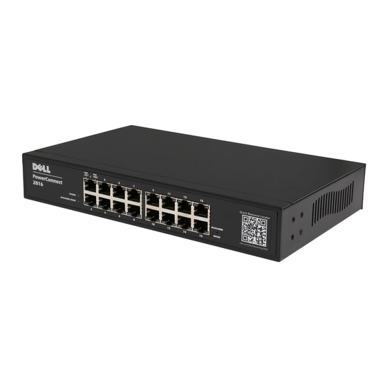
Figure 1-2. PowerConnect 2816 Front Panel The PowerConnect 2816 supports the following ports: • 16 Gigabit Ethernet copper ports PowerConnect 2824 The following figure illustrates the PowerConnect 2824 front panel. Figure 1-3. PowerConnect 2824 Front Panel The PowerConnect 2824 supports the following ports: •... -
Page 11: Summary Of Powerconnect Models
On half-duplex links, the receiving port prevents buffer overflows by occupying the link so that it is unavailable for additional incoming traffic. The user may enable or disable this feature on a per-port basis. The default status on all ports is set to OFF. Dell PowerConnect 28xx Systems User Guide... - Page 12 Cable analysis is available on Copper Cables (10BASE-T/100BASE-T/1000BASE-T), and is only done when the link is down. When the system initiates a cable-testing operation, upon explicit user action, the following parameters are detected: • Cable Type and Status • Cable Length • Fault-Distance Dell PowerConnect 28xx Systems User Guide...
-
Page 13: Mac Address Supported Features
Green Ethernet, also known as Energy Efficient Ethernet, is an effort to make networking equipment environmentally friendly, specifically by reducing power usage of Ethernet connections. The following methods are supported by the device: • Energy-Detect — Auto-detection of inactivity on a port, and subsequent reducing of transmit power. Dell PowerConnect 28xx Systems User Guide... -
Page 14: Vlan Supported Features
The PowerConnect 28xx switches support up to six aggregated links. Each of the six aggregated links may be defined with up to four member ports to form a single Link Aggregated Group (LAG). The benefits of this facility are: • Fault tolerance protection from physical link disruption Dell PowerConnect 28xx Systems User Guide... -
Page 15: Spanning Tree Protocol Features
Rapid Spanning Tree (RSTP) detects uses of network topologies to enable faster convergence, without creating forwarding loops. STP Root Guard Root guard restricts the interface from functioning as the root port for the switch Dell PowerConnect 28xx Systems User Guide... -
Page 16: Class Of Service (Cos) Features
The switches support one RMON group for Ethernet statistics. The system provides a means to collect the statistics defined in RMON and to view the results, using the Web management interface in the system. Dell PowerConnect 28xx Systems User Guide... -
Page 17: Hardware Description
Switch Port Configurations PowerConnect 28xx Front and Back Panel Port Description The Dell™ PowerConnect™ 28xx switches use 10/100/1000BASE-T ports on the front panel for connecting to a network. The Gigabit Ethernet ports can operate at 10, 100 or 1000 Mbps. These ports support auto- negotiation, duplex mode (Half or Full duplex), and flow control. - Page 18 Figure 2-2. PowerConnect 2808 Back Panel Figure 2-3. PowerConnect 2816 Front Panel On the front panel there are 16 ports which are numbered 1 to 16, top down and left to right. On each port there are LEDs to indicate the port status.
- Page 19 For more information about management modes and transitioning between them, see "Management Modes" on page 49. Dell PowerConnect 28xx Systems User Guide...
- Page 20 The Fan LED indicates the device fan operations status, and the Power LED on the front panel indicates whether the device is powered on or not. A Mode push- Dell PowerConnect 28xx Systems User Guide...
-
Page 21: Physical Dimensions
• Width — 256 mm (10.079 in.) • Depth — 161.7 mm (6.366 in.) The PowerConnect 2816 and PowerConnect 2824 switches have the following physical dimensions: • Height — 43.2 mm (1.7008 in.) • Width — 330 mm (12.992 in.) •... -
Page 22: Power Led
10/100/1000BASE-T Port LEDs Each 10/100/1000BASE-T port has two LEDs. Speed/Link/Activity is indicated on the left LED and the duplex mode is indicated on the right LED. The following figure illustrates the RJ-45 10/100/1000BASE-T LEDs. Dell PowerConnect 28xx Systems User Guide... -
Page 23: Managed Mode Button
Modes" on page 49. Switch Ventilation Fan The PowerConnect 2848 switch has three fans and the PowerConnect 2824 switch has one fan for system ventilation. The PowerConnect 2808 and PowerConnect 2816 devices have no internal fans. Dell PowerConnect 28xx Systems User Guide... -
Page 24: Cables, Port Connections, And Pinout Information
The RJ-45 pin number allocation for the 10/100/1000BASE-T ports is listed in the following table. Table 2-7. RJ-45 Pin Number Allocation for 10/100/ 1000BASE-T Ethernet Port Pin No Function TxRx 1+ TxRx 1- TxRx 2+ TxRx 2- TxRx 3+ Dell PowerConnect 28xx Systems User Guide... -
Page 25: Sfp Ports
Receiver ground (common with transmitter ground) Receiver ground (common with transmitter ground) Receiver ground (common with transmitter ground) Receiver inverted data out; AC coupled. Receiver non-inverted data out; AC coupled. Receiver ground (common with transmitter ground) Dell PowerConnect 28xx Systems User Guide... -
Page 26: Power Connectors
The PowerConnect 28xx supports a single internal power supply to provide power for switching operations. The internal power supply supports input voltages between 100 and 240 VAC. The AC power connector is located on the back panel of the switch. Dell PowerConnect 28xx Systems User Guide... -
Page 27: Installing The Powerconnect Device
Do not install the device in an environment where the operating ambient temperature might exceed 45ºC (113ºF). • Ensure that the airflow around the front, sides, and back of the device is not restricted. Dell PowerConnect 28xx Systems User Guide... -
Page 28: Site Requirements
1 Place the box on a clean flat surface. 2 Open the box or remove the box top. 3 Carefully remove the device from the package and place it on a secure, stable and clean surface. 4 Remove all packing material. Dell PowerConnect 28xx Systems User Guide... -
Page 29: Mounting The Device
1 Place the supplied rack-mounting bracket on one side of the device ensuring the mounting holes on the device line up to the mounting holes on the rack mounting bracket. The following figure illustrates where to mount the brackets. Dell PowerConnect 28xx Systems User Guide... -
Page 30: Installing On A Flat Surface
2 Set the device on a flat surface, while leaving 2 inches (5.08 cm) on each side and 5 inches (12.7 cm) at the back. 3 Ensure that the device has proper ventilation. Dell PowerConnect 28xx Systems User Guide... -
Page 31: Installing On A Wall
3 Insert the supplied screws into the rack-mounting holes and tighten with a screwdriver. 4 Repeat the process for the wall-mounting bracket on the other side of the device. 5 Place the device on the wall in the location where the device is being installed. Dell PowerConnect 28xx Systems User Guide... -
Page 32: Connecting The Device
The RJ-45 ports on the Ethernet device support automatic Media-Dependent Interface/Media-Dependent Interface with internal crossover wiring (MDI/MDIX) operation under Auto-Negotiation mode. Standard straight-through twisted-pair cables can be used to connect to any other Ethernet network (systems, servers, switches or routers) that supports auto-negotiation. Dell PowerConnect 28xx Systems User Guide... -
Page 33: Connecting The Terminal To The Device
With Windows 2000 Service Pack 2, the arrow keys function properly in www.microsoft.com HyperTerminal’s VT100 emulation. Go to for information on Windows 2000, Windows XP, and Windows Vista service packs. Dell PowerConnect 28xx Systems User Guide... -
Page 34: Connecting A Device To A Power Supply
Starting and Configuring the Device. Figure 3-4. Connecting to Power Supply 3 After connecting the device to a power source, confirm that the device is connected and operating correctly by examining the LEDs on the front panel. Dell PowerConnect 28xx Systems User Guide... -
Page 35: Port Connections, Cables, And Pinout Information
The RJ-45pin number allocation for the 10/100/1000BaseT ports is listed in the table following. Table 3-2. RJ-45 Pin Number Allocation for 10/100/1000BaseT Ethernet Port Pin No Function TxRx 1+ TxRx 1- TxRx 2+ TxRx 2- TxRx 3+ TxRx 3- TxRx 4+ TxRx 4- Dell PowerConnect 28xx Systems User Guide... -
Page 36: Port Default Settings
It can be enabled per port. The back pressure mechanism prevents the transmitting side from transmitting additional traffic temporarily. The receiving side may occupy a link so it becomes unavailable for additional traffic. Dell PowerConnect 28xx Systems User Guide... -
Page 37: Switching Port Default Settings
Port speed and mode 10/100/1000BaseT copper: auto-negotiation full duplex Port forwarding state Enabled Port tagging No tagging Flow Control Back Pressure Off (disabled on ingress) MDIX (not user-configurable) On (relevant to coppers ports only) Dell PowerConnect 28xx Systems User Guide... - Page 38 Dell PowerConnect 28xx Systems User Guide...
-
Page 39: Starting And Configuring The Device
Before proceeding, read the release notes for this product. The release notes can be downloaded from http://support.dell.com. NOTE: It is recommended that you obtain the most recent revision of the user documentation from the Dell support website at http://support.dell.com. After completing all external connections, connect a terminal to the device to configure the device and for other procedures. -
Page 40: Booting The Device - Managed Mode
Once the device is set to operate as a managed switch the boot procedure can be monitored on the connected terminal as follows: 1 Ensure that the device console port is connected to a VT100 terminal device or VT100 terminal emulator via the RS-232 crossover cable. 2 Locate an AC power receptacle. Dell PowerConnect 28xx Systems User Guide... -
Page 41: Initial Configuration - Managed Mode
You can skip using the setup wizard and configure the device manually through the device CLI mode (see "Managing the Device Using the CLI" on page 157. The Setup Wizard configures the following fields. Dell PowerConnect 28xx Systems User Guide... - Page 42 Wizard Step 1 The following information displays: The system is not setup for SNMP management by default. To manage the switch using SNMP (required for Dell Network Manager) you can: *Setup the initial SNMP Version 2 account now *Return later and setup additional SNMP v1/v2 accounts For more information on setting up SNMP accounts, please see the user documentation.
- Page 43 [Privilege Level 15] to this account. You can use Dell Network Manager or CLI to change this setting, and to add additional management systems. For more information on adding management systems, see the user documentation.
-
Page 44: Advanced Configuration
Configuring SNMP management interface. Configuring user account..Configuring IP and subnet..Thank you for using Dell Easy Setup Wizard. Advanced Configuration This section provides information about dynamic allocation of IP addresses. When configuring/receiving IP addresses through DHCP, the configuration received from the server includes the IP address, and may include subnet mask and default gateway. -
Page 45: Retrieving An Ip Address From A Dhcp Server
************************************************** ------ Performing the Power-On Self Test (POST) ------ UART Channel Loopback Test......PASS Testing the System SDRAM......PASS Boot1 Checksum Test.......PASS Boot2 Checksum Test.......PASS Flash Image Validation Test.......PASS BOOT Software Version 1.0.0.20 Built 22-Jan-xxxx 15:09:28 Dell PowerConnect 28xx Systems User Guide... -
Page 46: Software Download
The length of time taken by the download varies according to the tool used. Erase FLASH File In some cases, the device configuration must be erased. If the configuration is erased, all parameters configured via CLI, EWS or SNMP must be reconfigured. Dell PowerConnect 28xx Systems User Guide... -
Page 47: Erasing The Device Configuration
1 Ensure that an IP address is configured on one of the device ports and pings can be sent to a TFTP server. 2 Make sure that the file to be downloaded is saved on the TFTP server (the ros file). Dell PowerConnect 28xx Systems User Guide... - Page 48 Erasing file..done. !!!!!!!!!!!!!!!!!!!!!!!!!!!!!!!!!!!!!!!!!!!!!!!!!!!!!!!!!!!!!!!!!!!! !!!!!!!!!!!!!!!!!!!!!!!!!!!!!!!!!!!!!!!!!!!!!!!!!!!!!!!!!!!!!!!! Copy: 2739187 bytes copied in 00:01:13 [hh:mm:ss] 4 Enter the reload command. The following message is displayed: console# reload This command will reset the whole system and disconnect your current Dell PowerConnect 28xx Systems User Guide...
-
Page 49: Management Modes
The factory default values, used when the device is in Unmanaged mode, include: • IP Address — 192.168.2.1 • Netmask — 255.255.255.0 • Username — admin • Permission — R/W privilege • DHCP Client — Off • Flow Control — On • STP — Off Dell PowerConnect 28xx Systems User Guide... -
Page 50: Transitioning Between Modes
Transitioning Between Modes The following diagram summarizes movement between modes: Figure 4-2. Transitioning Between Management Modes Dell PowerConnect 28xx Systems User Guide... -
Page 51: Returning To Managed Mode
Use Current IP/User Name/Password — When restoring local configuration, this option uses the system default IP address, user name and password. • Apply Changes — The selected configuration is restored and the device reboots. Dell PowerConnect 28xx Systems User Guide... - Page 52 Dell PowerConnect 28xx Systems User Guide...
-
Page 53: Using Dell Openmanage Switch Administrator
Device View — Located on the right side of the home page, the device view provides a view of the device, an information or table area, and configuration instructions. Figure 5-1. Switch Administrator Components Table 5-1 lists the interface components with their corresponding numbers. Dell PowerConnect 28xx Systems User Guide... -
Page 54: Device Representation
The components list contains a list of the feature components. Components can also be viewed by expanding a feature in the tree view. The information buttons provide access to information about the device and access to Dell Support. For more information, see "Information Buttons." Device Representation The PowerConnect home page contains a graphical device representation of the front panel. -
Page 55: Using The Switch Administrator Buttons
For example, if the IP Addressing page is open, the help topic for that page opens when Help is clicked. About Contains the version and build number and Dell copyright information. Log Out Logs out of the application and closes the browser window. -
Page 56: Device Management Buttons
The device can be managed via web interface only in Managed mode. For more information about management modes, see "Management Modes" on page 49. 4 Click OK. The Dell PowerConnect OpenManage™ Switch Administrator home page opens. Access Levels When you login to the device, you are automatically assigned one of the following modes, based upon... - Page 57 Monitor — This is a read-only mode where you can see a subset of the interface pages, but you cannot edit them. For more information about setting the access level, see ("Defining the Local User Databases" on page 69). Dell PowerConnect 28xx Systems User Guide...
- Page 58 Dell PowerConnect 28xx Systems User Guide...
-
Page 59: Configuring System Information
Configuring System Information This section provides information for defining system parameters including security features, downloading device software, and resetting the device. To open the System page, click System in the tree view. Figure 6-1. System Defining General Device Information The General page contains links to pages for configuring device parameters. Viewing Device Information The Asset page contains parameters for configuring general device information, including the system name, location, and contact, the system MAC Address, System Object ID, date, time, and... - Page 60 Figure 6-2. Asset • System Name (0-159 Characters) — Defines the user-defined device name. • System Contact (0-159 Characters) — Specifies the name of the contact person. • System Location (0-159 Characters) — Specifies the location where the system is currently running. •...
-
Page 61: Viewing The Versions Page
Defining System Information: 1 Open the Asset page. 2 Define the relevant fields. 3 Click Apply Changes. The system parameters are defined, and the device is updated. Initiating a Telnet Session: 1 Open the Asset page. 2 Click Telnet. A Telnet session is initiated. Viewing the Versions Page The Versions page contains information about the hardware and software versions currently running. -
Page 62: Resetting The Device
Resetting the Device The Reset page enables the device to be reset from a remote location. For more information about saved Configuration files, see "Managing Files" on page 80 To open the Reset page click System General → → Reset in the tree view. Figure 6-4. -
Page 63: Entering Secure Mode
Entering Secure Mode Secure The Secure Mode page allows you to put the device in the management mode. Once enabled, it prevents users from making any further configuration changes to the switch. This is done by removing the IP address of the switch so that it becomes inaccessible. In Secure Mode the switch retains configuration through power cycles just like in Managed Mode. -
Page 64: Defining Device Ip Addresses
Defining Device IP Addresses The IP Addressing page contains links for assigning interface and default gateway IP addresses, and enabling or disabling DHCP . To open the IP Addressing page, click System IP Addressing in the tree view. → Defining IP Interface Parameters The IP Interface Parameters page is used to select whether the device IP address, mask and/or gateway is assigned statically, or dynamically using DHCP . -
Page 65: Running Cable Diagnostics
• DHCP Default Gateway — Defines the Default Gateway Address received from the DHCP server. • Apply DHCP Address — Activates the IP Address, Subnet Mask Address, and Default Gateway Address, received from the DHCP server. Enabling DHCP: 1 Open the IP Interface Parameters page 2 Set DHCP to Enable. - Page 66 Figure 6-7. Integrated Cable Test for Copper Cables • Port — The port to which the cable is connected. • Test Result — The cable test results. Possible values are: – No Cable — There is no cable connected to the port. Open Cable —...
-
Page 67: Viewing Optical Transceiver Diagnostics
Displaying Virtual Cable Test Results Table 1 Open the Integrated Cable Test for Copper Cables page. 2 Click Show All. The Virtual Cable Test Results Table opens. Viewing Optical Transceiver Diagnostics The Optical Transceiver Diagnostics page contains fields for performing tests on Fiber Optic cables. Optical transceiver diagnostics can be performed only when the link is present. - Page 68 • Loss of Signal — Indicates if a signal loss occurred in the cable. • Data Ready — The transceiver has achieved power up and data is ready. Displaying Optical Transceiver Diagnostics Test Results Table 1 Open the Optical Transceiver Diagnostics page. 2 Click Show All.
-
Page 69: Managing Device Security
Managing Device Security The Management Security page provides access to security pages that contain fields for setting security parameters for user database, password and RADIUS security. To open the Management Security page click System→Management Security in the tree view. Defining the Local User Databases The Local User Database page contains fields for defining users, passwords and access levels. - Page 70 4 Click Apply Changes. The user access rights and passwords are defined, and the device is updated. Defining a New User: 1 Open the Local User Database page. 2 Click Add. The Add User page opens: Figure 6-10. Add a User 3 Define the fields.
-
Page 71: Configuring Radius Global Parameters
2 Click Show All. The Local User Table opens. 3 Select a User Name. 4 Select the Remove check box. 5 Click Apply Changes. The selected user is deleted and the device is updated. Configuring RADIUS Global Parameters Remote Authorization Dial-In User Service (RADIUS) servers provide additional security for networks. - Page 72 • Priority (0-65535) — Specifies the server priority. The possible values are 0-65535, where 0 is the highest value. This is used to configure the order in which servers are queried. • Authentication Port — Identifies the authentication port. The authentication port is used to verify the RADIUS server authentication.
- Page 73 2 Click Add. The Add RADIUS Server page opens: Figure 6-13. Add RADIUS Server Page 3 Define the fields. 4 Click Apply Changes. The new RADIUS server is added, and the device is updated. Displaying the RADIUS Server List: 1 Open the RADIUS Settings page. 2 Click Show All.
-
Page 74: Defining Snmp Parameters
2 Click Show All. The RADIUS Servers List page opens. 3 Modify the relevant fields. 4 Click Apply Changes. The RADIUS Server settings are modified, and the device is updated. Deleting a RADIUS Server for the RADIUS Servers List: 1 Open the RADIUS Settings page. 2 Click Show All. -
Page 75: Defining Snmp Global Parameters
Defining SNMP Global Parameters The SNMP Global Parameters page permits enabling both SNMP and Authentication notifications.To open the SNMP Global Parameters page, click System → SNMP → Global Parameters in the tree view. Figure 6-15. Global Parameters • SNMP Notifications — Enables or disables the device sending SNMP notifications. •... -
Page 76: Defining Communities
Defining Communities Access rights are managed by defining communities in the Community Table. When the community names are changed, access rights are also changed.To open the SNMP Community page, click System → SNMP → Community in the tree view. Figure 6-16. SNMP Community •... - Page 77 Figure 6-17. Add SNMP Community 3 Select one of the following: – SNMP Management Station — Defines an SNMP community for a specific management station. – All — Defines an SNMP community for all management stations. 4 Define the remaining fields. 5 Click Apply Changes.
-
Page 78: Defining Snmp Notification Recipients
4 Select the Remove check box. 5 Click Apply Changes. The selected community entry is deleted, and the device is updated. Defining SNMP Notification Recipients The Notification Recipients page contains information for defining filters that determine whether traps are sent to specific users, and the trap type sent. SNMP notification filters provide the following services: •... - Page 79 – SNMPv2 — SNMP Version 2 traps are sent. • Remove Notification Recipient — When checked, removes selected notification recipients. Adding a new Trap Recipients 1 Open Notification Recipients page. 2 Click Add. The Add Notification Recipients page opens: 3 Define the relevant fields. 4 Click Apply Changes.
-
Page 80: Managing Files
2 Click Show All. The Notification Recipients Tables page opens. 3 Select a notification recipient. 4 Check the Remove checkbox. 5 Click Apply Changes. The recipient is deleted, and the device is updated. Managing Files The File Management page contains fields for managing device software, the Image Files, and the Configuration Files. - Page 81 Figure 6-21. File Download From Server • Firmware Download — The Firmware file is downloaded. If Firmware Download is selected, the Configuration Download fields are grayed out. • Configuration Download — The Configuration file is downloaded. If Configuration Download is selected, the Firmware Download fields are grayed out.
-
Page 82: Uploading Files
• Source File Name (1-64 Characters) — Indicates the configuration files to be downloaded. During the image file download, a dialog box opens which displays the download progress. Downloading Files 1 Open the File Download From Server page. 2 Define the fields. 3 Click Apply Changes. -
Page 83: Restoring Default Settings
Uploading Files 1 Open the File Upload to Server page. 2 Define the fields. 3 Click Apply Changes. The software is uploaded to the device. Restoring Default Settings The Restore Defaults page allows you to restore the device settings to their factory default values. To open the Restore Defaults page, click System →... -
Page 84: Configuring Dhcp Properties
The DHCP server uses a defined pool of IP addresses (user-defined) from which it allocates IP addresses to DHCP clients. The DHCP server can allocate IP addresses in three configuration modes: Static allocation — The network administrator maps the hardware address of a host to an IP address •... -
Page 85: Defining Network Pool
• DHCP Ping — Indicates if the DHCP server is set to ping the offered IP address before responding to a client request, to ensure that the address is not in use. The possible field values are: – Enable — Enables ping on the DHCP server. Disable —... - Page 86 Figure 6-25. Network Pool • Subnet IP Address — Specifies the IP address of the subnet in which the network pool resides. Network Mask — Specifies the pool’s network mask. • • Prefix Length — Specifies the number of bits that comprise the address prefix. •...
-
Page 87: Excluding Addresses
• Domain Name — Specifies the domain name for a DHCP client. The domain name may contain up to 32 characters. • NetBIOS WINS Server — Specifies the NetBIOS WINS name server available to a DHCP client. NetBIOS Node Type — A parameter that informs the workstation how to resolve the NetBIOS name. •... - Page 88 Figure 6-26. Excluded Addresses • Start IP Address — Displays the first IP address in the range of excluded IP addresses. • End IP Address — Displays the last IP address in the range of excluded IP addresses. Adding an Excluded Address 1 Open the Excluded Addresses page.
-
Page 89: Manually Allocating Ip Addresses (Static Hosts)
Manually Allocating IP Addresses (Static Hosts) The Static Hosts page is used to manually allocate IP addresses to network hosts. To open the Static Hosts page, click System DHCP Server Static Hosts in the tree view. → → Figure 6-28. Static Hosts Host Name —... - Page 90 • NetBIOS WINS Server — Specifies the NetBIOS WINS name server available to a Microsoft DHCP static host. • NetBIOS Node Type — Informs the workstation how to resolve the NetBIOS name. Valid node types are: – Blank — The workstation is not informed as to which type of NetBIOS node the client is. –...
- Page 91 Figure 6-29. Add Static Host 3 Define the relevant fields. 4 Click Apply Changes. The static host is added, and the device is updated. Displaying Static Hosts Tables 1 Open the Static Hosts page. 2 Click Show All. The Static Hosts Table page opens: Figure 6-30.
-
Page 92: Configuring Address Binding
Deleting Static Hosts 1 Open the Static Hosts page. 2 Click Show All. The Static Hosts Table page opens. 3 Check the Remove checkbox next to a static host. 4 Click Apply Changes. The host is deleted, and the device is updated. Configuring Address Binding The Address Binding page displays a list of the DHCP server’s allocated IP addresses and each IP address’s client identifier, lease expiration time, and allocation type. -
Page 93: Defining Advanced Settings
Defining Advanced Settings The Advanced Settings page contains information for configuring general settings. Use Advanced Settings to set miscellaneous global attributes for the device. The changes to these attributes are applied only after the device is reset. To open the Advanced Settings page, click System Advanced Settings in →... - Page 94 Update with your book title...
-
Page 95: Configuring Device Switching
Configuring Device Switching This section provides all system operation and general information for configuring network security, ports, Address tables, GARP , VLANs, Spanning Tree, Port Aggregation, and Multicast Support. Configuring Network Security The device enables network security through both Access Control Lists and Locked Ports. Port Based Authentication (802.1x) Port based authentication enables authenticating system users on a per-port basis via a external server. -
Page 96: Configuring Port Based Authentication
Advanced Port Based Authentication is implemented in the following modes: • Single Host Mode — Enables only the authorized host for single-session access to the port. • Multiple Host Mode — Enables multiple hosts to be attached to a single port, for single-session access. - Page 97 – None — No authentication method is used to authenticate the port. – RADIUS — Port authentication is performed using the RADIUS server. – RADIUS, None — Port authentication is performed first using the RADIUS server. If the port is not authenticated, then no authentication method is used, and the session is permitted.
- Page 98 – Authenticated ports remain unauthenticated VLAN and Guest VLAN members. Static VLAN configuration is not applied to the port. – The following list of VLANs cannot participate in DVA: an Unauthenticated VLAN, a Dynamic VLAN that was created by GVRP, a Voice VLAN, a Default VLAN and a Guest VLAN. –...
- Page 99 Figure 7-2. Port Based Authentication Table Termination Cause — The reason for which the port authentication was terminated. Copy To Checkbox — Copies port parameters from one port to the selected ports. Select All — Selects all ports in the Port Based Authentication Table. Copying Parameters in the Port Based Authentication Table 1 Open the Port Based Authentication page.
-
Page 100: Configuring Advanced Port Based Authentication
Configuring Advanced Port Based Authentication The Multiple Hosts page provides information for defining advanced port based authentication settings for specific ports. To open the Multiple Hosts, click Switch →Network Security → Multiple Hosts. Figure 7-3. Multiple Hosts • Port — The port number for which Advanced Port Based Authentication is enabled. •... - Page 101 • Trap Frequency (1-1000000) (Sec) — Defines the time period by which traps are sent to the host. The Trap Frequency (1-1000000) field can be defined only if the Multiple Hosts field is defined as Disable. The default is 10 seconds. •...
-
Page 102: Authenticating Users
Authenticating Users The Authenticated Users page displays user port access lists. To open the Authenticated Users page, click Switch → Network Security → Authenticated Users. Figure 7-5. Authenticated Users • User Name — List of users authorized via the RADIUS Server. •... -
Page 103: Configuring Ports
Configuring Ports The Ports page contains links to port functionality pages including advanced features, such as Green Ethernet, Storm Control and Port Mirroring. To open the Ports page, click Switch → Ports. Defining Port Parameters The Port Configuration page contains fields for defining port parameters. To open the Port Configuration page, click Switch →... - Page 104 • Admin Speed — The configured rate for the port. The port type determines what speed setting options are available. Admin speed can only be designated when auto negotiation is disabled on the configured port. • Current Port Speed — The actual currently configured port speed (bps). •...
-
Page 105: Aggregating Ports
Defining Port Parameters 1 Open the Port Configuration page. 2 Select a port in the Port Field. 3 Define the remaining fields. 4 Click Apply Changes. The port parameters are saved to the device. Modifying Port Parameters 1 Open the Port Configuration page. 2 Select a port in the Port Field. - Page 106 The LAG Configuration page contains fields for configuring parameters for configured LAGs. The device supports up to four LAGs, each having six members. For information about Link Aggregated Groups and assigning ports to LAGs, refer to Aggregating Ports. To open the LAG Configuration page, click Switch→ Ports→ LAG Configuration in the tree view. If port configuration is modified while the port is a LAG member, the configuration change is only effective after the port is removed from the LAG.
- Page 107 • Admin Status — Enables or disables traffic forwarding through the selected LAG. • Current LAG Status — Indicates if the LAG is currently operating. • Operational Status — Operational status of the LAG. • Admin Auto Negotiation — Enables or disables Auto Negotiation on the LAG. Auto-negotiation is a protocol between two link partners that enables a LAG to advertise its transmission rate and flow control (the flow control default is enabled) abilities to its partner.
-
Page 108: Configuring Green Ethernet
The LAG Configuration Table opens: Figure 7-10. LAG Configuration Table Configuring Green Ethernet Green Ethernet, also known as Energy Efficient Ethernet, is an effort to make networking equipment environmentally friendly, specifically by reducing power usage of Ethernet connections. The following methods are supported by the device: •... - Page 109 Figure 7-11. Green Ethernet Configuration • Cumulative Energy Saved — The total amount of energy saved since the last reset. This amount is equal to the saved power multiplied by the time period in hours. Reset — Click to set the Cumulative Power Saved counter back to 0. –...
-
Page 110: Enabling Storm Control
The Green Ethernet Ports Table includes the following port energy saving information: • Port — Indicates the port. • Energy-Detect — The status of the Energy-Detect mode on the link: – Admin — Whether the Energy-Detect has been enabled for the port. –... - Page 111 Figure 7-12. Storm Control • Port — The port from which storm control is enabled. Broadcast Control — Enables or disables forwarding broadcast packet types on the device. • • Mode — Specifies the Broadcast mode currently enabled on the device. The possible field value are: —...
-
Page 112: Defining Port Mirroring Sessions
Figure 7-13. Storm Control Table Defining Port Mirroring Sessions Port mirroring monitors and mirrors network traffic by forwarding copies of incoming and outgoing packets from one port or a number of ports (source port or ports) to a monitoring (destination) port. Port mirroring is configured by selecting a specific port to copy all packets, and different ports from which the packets copied. - Page 113 The following restrictions apply to ports configured to be source ports: • Source Ports cannot be a LAG member. • Ports cannot be configured as a destination port. • All packets are transmitted tagged from the destination port. • Monitored all RX/TX packets to the same port. To open the Port Mirroring page, click Switch→...
-
Page 114: Configuring Address Tables
6 Click Apply Changes. The new source port is defined, and the device is updated. Deleting a Copy Port from a Port Mirroring Session 1 Open the Port Mirroring page. 2 Select the Remove check box. 3 Click Apply Changes. The selected port mirroring session is deleted, and the device is updated. - Page 115 Figure 7-15. Dynamic Address Table • Address Aging (10-630) — Specifies the amount of time the MAC Address remains in the Dynamic Address Table before it is timed out if no traffic from the source is detected. The default value is 300 seconds.
-
Page 116: Configuring The Spanning Tree Protocol
Querying the Dynamic Address Table 1 Open the Dynamic Address Table. 2 Define the parameter by which to query the Dynamic Address Table. Entries can be queried by Port, MAC Address, or VLAN ID. 3 Click Query. The Dynamic Address Table is queried. Sorting the Dynamic Address Table 1 Open the Dynamic Address Table. - Page 117 Figure 7-16. STP Global Settings • Spanning Tree State — Enables or disables Spanning Tree on the device. The possible field values are: – Enable — Enables Spanning Tree – Disable — Disables Spanning Tree • STP Operation Mode — The STP mode by which STP is enabled on the device. The possible field values are: –...
- Page 118 • Priority (0-61440 in steps of 4096) — Specifies the bridge priority value. When switches or bridges are running STP, each is assigned a priority. After exchanging BPDUs, the switch with the lowest priority value becomes the Root Bridge. The default value is 32768. The bridge priority value is provided in increments of 4096 (4K increments).
-
Page 119: Defining Stp Port Settings
Defining STP Port Settings The STP Port Settings page contains fields for assigning STP properties to individual ports. To open the STP Port Settings page, click Switch→ Spanning Tree→ Port Settings in the tree view. Figure 7-17. STP Port Settings Select a Port —... - Page 120 • Port State — The current port STP state. If enabled, the port state determines what forwarding action is taken on traffic. Possible port states are: – Disabled — The port link is currently down. Blocking — The port is currently blocked and cannot be used to forward traffic or learn MAC –...
- Page 121 • Priority (0-240, in steps of 16) — The priority value of the port. The priority value influences the port choice when a bridge has two ports connected in a loop. The priority value is between 0-240. The priority value is provided in increments of 16. •...
-
Page 122: Defining Stp Lag Settings
Defining STP LAG Settings The STP LAG Settings page contains fields for assigning STP aggregating port parameters. To open the STP LAG Settings page, click Switch→ Spanning Tree→ LAG Settings in the tree view. Figure 7-18. STP LAG Settings • Select a LAG —... - Page 123 • LAG State — Current STP state of a LAG. If enabled, the LAG state determines what forwarding action is taken on traffic. If the bridge discovers a malfunctioning LAG, the LAG is placed in the Broken state. Possible LAG states are: –...
-
Page 124: Configuring Rapid Spanning Tree
Modifying the LAG STP Parameters 1 Open the STP LAG Settings page. 2 Select a LAG from the Select a LAG drop-down menu. 3 Modify the fields as desired. 4 Click Apply Changes. The STP LAG parameters are modified, and the device is updated. Configuring Rapid Spanning Tree While Classic Spanning Tree guarantees preventing L2 forwarding loops in a general network topology, convergence can take up to 30-60 seconds. - Page 125 Figure 7-19. Rapid Spanning Tree (RSTP) • Interface — Port or LAG on which Rapid STP is enabled. • Role — The port role assigned by the STP algorithm in order to provide to STP paths. The possible field values are: –...
-
Page 126: Configuring Vlans
– Disable — Device establishes shared, half duplex links. – Auto — Device automatically determines the state. • Point-to-Point Operational Status — Displays the point-to-point operating state which depends on a link partner. • Activate Protocol Migration Test — Select to run a Protocol Migration Test. The test identifies the STP mode of the interface connected to the selected interface. - Page 127 Figure 7-20. VLAN Membership • Show VLAN — Lists and displays specific VLAN information according to VLAN ID or VLAN name. • VLAN Name — The user-defined VLAN name. • Unauthorized Users — Enables or disables unauthorized users from accessing a VLAN. •...
-
Page 128: Vlan Port Membership Table
Figure 7-21. Create New VLAN 3 Enter the VLAN ID and name. 4 Click Apply Changes. The new VLAN is added, and the device is updated. Modifying VLAN Membership Groups 1 Open the VLAN Membership page. 2 Select a VLAN from the Show VLAN drop-down menu. 3 Modify the fields as desired. - Page 129 Table 7-1. VLAN Port Membership Table Port Control Definition The interface is a VLAN member. Packets forwarded by the interface are untagged. The interface is denied membership to a VLAN. The interface is not a VLAN member. Packets associated with the interface are not Blank forwarded.
-
Page 130: Defining Vlan Ports Settings
Defining VLAN Ports Settings The VLAN Port Settings page contains fields for managing ports that are part of a VLAN. The port default VLAN ID (PVID) is configured on the VLAN Port Settings page. All untagged packets arriving to the device are tagged by the ports PVID. To open the VLAN Port Settings page, click Switch VLAN Port Settings in the tree view. -
Page 131: Defining Vlan Lag Settings
Displaying the VLAN Port Table 1 Open the VLAN Port Settings page. 2 Click Show All. The VLAN Port Table opens. Figure 7-23. VLAN Port Table Defining VLAN LAG Settings The VLAN LAG Setting page provides parameters for managing LAGs that are part of a VLAN. VLANs can either be composed of individual ports or of LAGs. - Page 132 Figure 7-24. VLAN LAG Setting • LAG — The LAG number included in the VLAN. • PVID — Assigns a VLAN ID to untagged packets. The possible field values are 1-4095. VLAN 4095 is defined as per standard and industry practice, as the discard VLAN. Packets classified to this VLAN are dropped.
-
Page 133: Aggregating Ports
Aggregating Ports Port Aggregation optimizes port usage by linking a group of ports together to form a single Link Aggregated Group (LAG). Port Aggregation multiplies the bandwidth between the devices, increases port flexibility, and provides link redundancy. The device supports up to four LAGs, each having six members. -
Page 134: Defining Lag Membership
Defining LAG Membership The LAG Membership page contains fields for assigning ports to LAGs. LAGs can include up to 6 ports. When a port is added to a LAG, the port acquires the LAG’s properties. If the port cannot be configured with the LAG properties, a trap is generated and the port operates with its default settings. -
Page 135: Defining Multicast Global Parameters
Defining Multicast Global Parameters Layer 2 switching forwards Multicast packets to all relevant VLAN ports by default, treating the packet as a Multicast transmission. While this is functional, in the sense that all relevant ports/nodes receive a copy of the frame, it is potentially wasteful as ports/nodes may receive irrelevant frames only needed by a subset of the ports of that VLAN. -
Page 136: Adding Bridge Multicast Address Members
Enabling IGMP Snooping on the Device 1 Open the Multicast Global Parameters page. 2 Select Enable in the IGMP Snooping Status field. 3 Click Apply Changes. IGMP Snooping is enabled on the device. Adding Bridge Multicast Address Members The Bridge Multicast Group page displays the ports and LAGs attached to the Multicast service group in the Ports and LAGs tables. - Page 137 • Ports — Port that can be added to a Multicast service. • LAGs — LAGs that can be added to a Multicast service. The following table contains the IGMP port and LAG members management settings: The port/LAG has joined the Multicast group dynamically in the Current Row.
-
Page 138: Assigning Multicast Forward All Parameters
4 Toggle a port to S to join the port to the selected Multicast group. 5 Toggle a port to F to forbid adding specific Multicast addresses to a specific port. 6 Click Apply Changes. The bridge Multicast address is assigned to the Multicast group, and the device is updated. Defining Ports to Receive Multicast Service 1 Open the Bridge Multicast Group page. - Page 139 Figure 7-29. Bridge Multicast Forward All • VLAN ID — Identifies a VLAN. • Ports — Ports that can be added to a Multicast service. • LAGs — LAGs that can be added to a Multicast service. The contains the settings for managing router and port settings. Port Control Definition The port/LAG is excluded from this Multicast...
- Page 140 Attaching a Port to a Multicast Router or Switch 1 Open Bridge Multicast Forward All page. 2 Define the VLAN ID field. 3 Select a port in the Ports table, and assign the port a value. 4 Click Apply Changes. The port is attached to the Multicast router or switch.
-
Page 141: Igmp Snooping
IGMP Snooping The IGMP Snooping page contains fields for adding IGMP members. To open the IGMP Snooping page, click Switch→ Multicast Support→ IGMP Snooping in the tree view. Figure 7-30. IGMP Snooping • VLAN ID — Specifies the VLAN ID. •... - Page 142 Enabling IGMP Snooping on the Device 1 Open the IGMP Snooping page. 2 Select the VLAN ID for the device on which IGMP snooping needs to be enabled. 3 Select Enable in the IGMP Snooping Status field. 4 Complete the fields on the page. 5 Click Apply Changes.
-
Page 143: Viewing Statistics
Viewing Statistics The Statistic pages contains links to device information for RMON, and CPU utilization. Update with your book title... -
Page 144: Viewing Rmon Statistics
Viewing RMON Statistics Remote Monitoring (RMON) contains links for viewing network information from a remote location. To open the RMON page, click Statistics/RMON→ RMON in the tree view. Viewing RMON Statistics Group The RMON Statistics Group page contains fields for viewing information about device utilization and errors that occurred on the device. -
Page 145: Viewing Charts
• Interface — Specifies the port or LAG for which statistics are displayed. • Refresh Rate — Amount of time that passes before the statistics are refreshed. • Drop Events — Number of dropped events that have occurred on the interface since the device was last refreshed. -
Page 146: Viewing The Cpu Utilization
Viewing the CPU Utilization The CPU Utilization page contains information about the system’s CPU utilization and percentage of CPU resources consumed by each stacking member. Each stacking member is assigned a color on the graph. The range of the utilization reading is from 0 to 200%. The maximum reading of 200% for a full duplex connection indicates that 100% of bandwidth of incoming and outgoing connections is used by the traffic traveling through the interface. -
Page 147: Configuring Quality Of Service
Configuring Quality of Service This section provides information for defining and configuring Quality of Service (QoS) parameters. To open the Quality of Service page, click Quality of Service in the tree view. An implementation example that requires QoS includes certain types of traffic such as Voice, Video and real-time traffic which can be assigned a high priority queue, while other traffic can be assigned a lower priority queue. - Page 148 DSCP values can be mapped to priority queues. The following table contains the default DSCP mapping to forwarding queue values: Table 9-2. DSCP to Queue Mapping Table Default Values DSCP Value Forwarding Queue Values 0-15 16-31 32-47 48-63 DSCP mapping is enabled on a per-system basis. CoS Services After packets are assigned to a specific queue, CoS services can be assigned to the queue(s).
-
Page 149: Defining Cos Global Parameters
Defining CoS Global Parameters Class of Service (CoS) global parameters are set from the CoS Settings page. To open the CoS Settings page, click Quality of Service→ CoS Global Parameters → CoS Settings in the tree view. Figure 9-1. CoS Settings •... -
Page 150: Defining Qos Interface Settings
Trust is selected. Defining QoS Interface Settings The Interface Settings page contains fields for defining, per interface, if the selected Trust mode is to be activated. The default priority for incoming untagged packets is also selected in the Interface Settings page. -
Page 151: Defining Queue Settings
2 Click Show All. The QoS Interface Settings Table page opens: Figure 9-3. QoS Interface Settings Table Defining Queue Settings The QoS Queue Settings page contains fields for configuring the scheduling method by which the queues are maintained. To open the QoS Queue Settings page click Quality of Service→ CoS Global Parameters→... - Page 152 • WRR — Specifies if traffic scheduling is based on the Weighted Round Robin (WRR) weights to egress queues. The default values are: – 8 for Queue 1 – 4 for Queue 2 – 2 for Queue 3 – 1 for Queue 4 •...
-
Page 153: Mapping Cos Values To Queues
Mapping CoS Values to Queues The CoS to Queue Mapping Table page contains fields for classifying CoS settings to traffic queues. To open the CoS to Queue Mapping Table page, click Quality of Service→ CoS Global Parameters→ CoS to Queue in the tree view. Figure 9-5. -
Page 154: Mapping Dscp Values To Queues
Mapping DSCP Values to Queues The DSCP to Queue page provides fields for defining output queue to specific DSCP fields. For the list of the DSCP default queue settings, see "DSCP to Queue Mapping Table Default Values" on page 148. To open the DSCP to Queue page, click Quality of Service→... - Page 155 1 Open the DSCP to Queue page. 2 Check the Restore Defaults checkbox. 3 Click Apply Changes. The default values are restored. Update with your book title...
- Page 156 Update with your book title...
-
Page 157: A Managing The Device Using The Cli
The device supports up to four simultaneous Telnet sessions. All CLI commands can be used over a telnet session. To start a Telnet session: 1 Select Start > Run. The Run window opens. Dell PowerConnect 28xx Systems User Guide... -
Page 158: Using The Cli
The user EXEC commands permit connecting to remote devices, changing terminal settings on a temporary basis, performing basic tests, and listing system information. To list the user EXEC commands, enter a question mark at the command prompt. Dell PowerConnect 28xx Systems User Guide... -
Page 159: Privileged Exec Mode
To list the Global Configuration commands, enter a question mark at the command prompt. To return from Global Configuration mode to Privileged EXEC mode, type the exit command or use the <Ctrl><Z> command. Dell PowerConnect 28xx Systems User Guide... -
Page 160: Interface Configuration Mode
Console (config-if)# Port Channel Mode The Port Channel mode contains commands for configuring Link Aggregation Groups (LAG). The following is an example of the Port Channel mode prompt: Console (config)# interface port-channel 1 Console (config-if)# Dell PowerConnect 28xx Systems User Guide... -
Page 161: Cli Commands
Source for the file from a serial connection that uses the Xmodem protocol. null: Null destination for copies or files. You can copy a remote file to null to determine its size. Dell PowerConnect 28xx Systems User Guide... -
Page 162: Command: Debug-Mode
Command: debug-mode To switch to debug mode, use the debug-mode command in Privileged EXEC mode. debug-mode Syntax Description This command has no arguments or keywords. Command Mode Privileged EXEC Dell PowerConnect 28xx Systems User Guide... -
Page 163: Command: Do
To exit any configuration mode to the next highest mode in the CLI mode hierarchy, use the exit command in any configuration mode. exit Syntax Description This command has no arguments or key words Dell PowerConnect 28xx Systems User Guide... -
Page 164: Command: Exit (Exec)
Example Console> exit Command: help To display a brief description of the help system, enter the help command. help Syntax Description This command has no arguments or key words Command Mode All command modes. Dell PowerConnect 28xx Systems User Guide... -
Page 165: Command: Interface Ethernet
Commands under the interface range context are executed independently on each interface in the range: If the command returns an error on one of the interfaces, it will not stop the execution of the command on other interfaces. Dell PowerConnect 28xx Systems User Guide... -
Page 166: Command: Interface Vlan
Command: ip address To set the IP address of a device interface, use the ip address interface configuration command. ip address ip-address Syntax Description ip-address • — The IP address to be assigned to the interface. Dell PowerConnect 28xx Systems User Guide... -
Page 167: Command: Ip Default-Gateway
Use the ping command to send ICMP echo request packets to another node on the network. ip-address hostname packet_size packet_count time_out ping { } [size ] [count ] [timeout Syntax Description ip-address • — IP address to ping. Dell PowerConnect 28xx Systems User Guide... - Page 168 Pinging 10.1.1.1 with 64 bytes of data: 64 bytes from 10.1.1.1: icmp_seq=0. time=11 ms 64 bytes from 10.1.1.1: icmp_seq=1. time=8 ms 64 bytes from 10.1.1.1: icmp_seq=2. time=8 ms 64 bytes from 10.1.1.1: icmp_seq=3. time=7 ms Dell PowerConnect 28xx Systems User Guide...
-
Page 169: Commad: Reload
Default value This command has no default setting. Command: show tech-support command To display system and configuration information you can provide to the Technical Assistance Center when reporting a problem, use the show tech-support command. Dell PowerConnect 28xx Systems User Guide... - Page 170 Dell PowerConnect 28xx Systems User Guide...
-
Page 171: Command: Snmp-Server Community
— Management station IPv4 address. Default is all IP addresses. Parameters range community • — 1 - 20 chars ip-address • — Valid IP address Default No community is defined Command Mode Global configuration Dell PowerConnect 28xx Systems User Guide... -
Page 172: Command: Username
— 1 - 20 characters. password • — 1 - 159 level • — 1 - 15 Default No user is defined. Command modes Global Configuration Example Console (config)# username bob password lee privilege 15 Dell PowerConnect 28xx Systems User Guide... -
Page 173: Glossary
Glossary This glossary contains key technical words of interest. Auto-negotiation Access Mode Allows 10/100 Mpbs or 10/100/1000 Mbps Ethernet ports to establish for the following features: Specifies the method by which user access is granted to the system. • Duplex/ Half Duplex Mode Access Profiles •... - Page 174 Broadcasting Baud The number of signaling elements transmitted each A method of transmitting packets to all ports on a second. network. Best Effort Broadcast Storm Traffic is assigned to the lowest priority queue, and An excessive amount of broadcast messages simultaneously transmitted across a network by a packet delivery is not guaranteed.
- Page 175 Half Duplex Mode — Permits asynchronous • communication, for example, a walkie-talkie. Command Line Interface . A set of line commands Only one party can transmit information at a used to configure the system. time. Dynamic VLAN Assignment (DVA) Communities Allows automatic assignment of users to VLANs Specifies a group of users which retains the same during the RADIUS server authentication.
- Page 176 Gigabit Ethernet Gigabit Ethernet transmits at 1000 Mbps, and is compatible with existing 10/100 Mbps Ethernet Fast Forward Table. Provides information about standards. forwarding routes. If a packet arrives to a device with a known route, the packet is forwarded via a route GVRP listed in the FFT.
- Page 177 IEEE Institute of Electrical and Electronics Engineers. Internetwork Packet Exchange . Transmits Engineering organization that develops connectionless communications. communications and networking standards. IEEE 802.1d Jumbo Frames Used in the Spanning Tree Protocol, IEEE 802.1d Enables transporting the identical data in fewer supports MAC bridging to avoid network loops.
- Page 178 Load Balancing Message Digest 5. An algorithm that produces a Enables the even distribution of data and/or 128-bit hash. MD5 is a variation of MD4, and processing packets across available network increases MD4 security. MD5 verifies the integrity resources. For example, load balancing may of the communication, authenticates the origin of distribute the incoming packets evenly to all servers, the communication.
- Page 179 • Fast Ethernet 100Mbps • Gigabit Ethernet 1000 Mbps Object Identifier. Protocol Used by SNMP to identify managed objects. In the SNMP Manager/ Agent A set of rules that governs how devices exchange network management paradigm, each managed information across networks. object must have an OID to identify it.
- Page 180 RSTP Rapid Spanning Tree Protocol System on a Chip . Detects and uses . An ASIC that contains an entire network topologies that allow a faster convergence system. For example, a telecom SoC application can of the spanning tree, without creating forwarding contain a microprocessor, digital signal processor, loops.
- Page 181 TCP/IP VLAN Transmissions Control Protocol Virtual Local Area Networks. . Enables two hosts Logical subgroups to communicate and exchange data streams. TCP with a Local Area Network (LAN) created via guarantees packet delivery, and guarantees packets software rather than defining a hardware solution. are transmitted and received in the order their sent.
- Page 182 Glossary...
-
Page 183: Index
Index Numerics Community table, 76 Fast link, 119 CoS, 150 File Transfer Protocol, 176 802.1d, 15 Filtering, 130, 132, 134 Firmware, 81 Flow Control, 36 Defining device Access mode, 76 FTP, 176 information, 59 Address Resolution Device installation, 30 Protocol, 173 Device representation, 54 Aggregated link, 133 Device view, 53-54... - Page 184 IEEE, 177 Management Information Port LEDs, 22 Base., 178 IEEE 802.1d, 177 Ports, 55, 103 Management security, 69 IEEE 802.1p, 177 PVID, 130, 132 Master Election/Topology IEEE 802.1Q, 177 Discovery Algorithm, 178 IGMP, 177 MD5, 178 Image File, 80, 177 MDI, 12, 104, 178 QoS, 150, 179 Ingress, 177...
- Page 185 Spanning Tree Protocol, 116, VLAN membership, 126 VLAN Port Membership Startup file, 80 Table, 128 Storm control, 110 VLAN priority, 147 STP, 15, 117, 125 VLANs, 126 System, 59 Web management system icons, 55 TFTP, 181 Weighted Round Robin, 151 Time Domain Reflectometry, 65 Width, 21...
- Page 186 Index...