Table of Contents
Advertisement
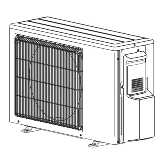
OUTDOOR UNIT
SERVICE MANUAL
Models
MXZ-2F33VF
-
E1
MXZ-2F33VF2
-
MXZ-2F33VF3
-
MXZ-2F33VF4
-
MXZ-2F42VF
-
E1
MXZ-2F42VF2
-
MXZ-2F42VF3
-
MXZ-2F42VF4
-
MXZ-2F53VF
-
E1
MXZ-2F53VF2
-
MXZ-2F53VF3
-
MXZ-2F53VF4
-
MXZ-2F53VFH
-
MXZ-2F53VFH2
MXZ-2F53VFH3
MXZ-2F53VFH4
MXZ-3F54VF
-
E1
MXZ-3F54VF2
-
MXZ-3F54VF3
-
MXZ-3F54VF4
-
Indoor unit service manual
MSZ-LN•VG Series (OBH766)
MSZ-LN•VG2 Series (OBH766)
MSZ-EF•VG Series (OBH589)
MSZ-AP•VF Series (OBH799)
MSZ-AP•VG Series (OBH788)
MSZ-BT•VG Series (OBH849)
MXZ-2F33VF
MXZ-2F33VF2
MXZ-2F42VF
MXZ-2F42VF2
MXZ-2F53VF
MXZ-2F53VF2
MXZ-2F53VFH
MXZ-2F53VFH2
,
ET1
,
E1
ET1
,
,
,
E1
ET1
ER1
E2
,
E1
ET1
,
ET1
,
E1
ET1
,
,
,
E1
ET1
ER1
E2
,
E1
ET1
,
ET1
,
E1
ET1
,
,
,
E1
ET1
ER1
E2
,
E1
ET1
E1
-
E1
-
,
E1
E2
-
E1
,
,
,
ET1
E2
ET2
,
E1
ET1
,
,
,
,
E1
ET1
ER1
E2
ET2
,
E1
ET1
MSZ-AY•VG Series (OBH930, 932)
MLZ-KP•VF Series (OBH801)
MFZ-KT•VG Series (OBH843)
MLZ-KY•VG Series (OBH921)
SLZ-M•FA Series (OCH522)
SEZ-M•DA Series (HWE17040)
MXZ-2F33VF3
MXZ-2F33VF4
MXZ-2F42VF3
MXZ-2F42VF4
MXZ-2F53VF3
MXZ-2F53VF4
MXZ-2F53VFH3
MXZ-2F53VFH4
Revision L:
• MXZ-2F33/42/53VF4 -
MXZ-2F53VFH4 -
MXZ-4F72/80VF4 -
MXZ-5F102VF2 -
MXZ-2F53VFHZ2 -
have been added.
OBH790 REVISED EDITION-K is void.
HFC
utilized
R32
MXZ-3F68VF
MXZ-3F68VF2
MXZ-3F68VF3
MXZ-3F68VF4
MXZ-4F72VF
MXZ-4F72VF2
MXZ-4F72VF3
MXZ-4F72VF4
MXZ-4F80VF2
MXZ-4F80VF3
MXZ-4F80VF4
MXZ-4F83VF
MXZ-4F83VF2
MXZ-5F102VF
MXZ-5F102VF2
MXZ-6F120VF2
MXZ-6F122VF
MXZ-2F53VFHZ
MXZ-2F53VFHZ2
,
ER2
MXZ-4F83VFHZ
MXZ-4F83VFHZ2
SFZ-M•VA Series (HWE19090)
PCA-M•KA Series (OCH659)
PEAD-M•JA(L) Series (HWE16130)
PEAD-M•JA(L)2 Series (HWE21070)
CONTENTS
•
COMPATIBILITY TABLE ·······················4
1. TECHNICAL CHANGES ······························7
2. SAFETY PRECAUTION ·······························9
3. PART NAMES AND FUNCTIONS ················ 19
4. SPECIFICATION ······································ 21
5. NOISE CRITERIA CURVES ························ 58
6. OUTLINES AND DIMENSIONS ··················· 62
7. WIRING DIAGRAM ··································· 70
8. REFRIGERANT SYSTEM DIAGRAM ··········111
9. PERFORMANCE CURVES ······················· 122
10. ACTUATOR CONTROL ··························· 171
11. SERVICE FUNCTIONS ···························· 172
12. TROUBLESHOOTING ····························· 179
13. DISASSEMBLY INSTRUCTIONS ··············· 214
PARTS CATALOG (OBB790)
,
,
E1
ET1
, MXZ-3F54/68VF4 -
E1
E1
,
, MXZ-4F83VF2 -
E1
ET1
,
, MXZ-6F120VF2 -
E1
ET1
and MXZ-4F83VFHZ2 -
E1
No. OBH790
REVISED EDITION-L
-
,
,
,
E1
ET1
E2
ET2
-
,
E1
ET1
-
,
,
E1
ET1
ER1
-
,
E1
ET1
-
,
,
,
E1
ET1
E2
ET2
-
,
E1
ET1
-
,
,
E1
ET1
ER1
-
,
E1
ET1
-
,
E1
ET1
-
,
E1
ET1
-
,
E1
ET1
-
,
,
E1
ET1
ER1
-
,
E1
ET1
-
,
,
E1
ET1
ER1
-
,
E1
ET1
-
,
E1
ET1
-
,
,
E1
ET1
ER1
-
,
E1
ER1
-
E1
-
,
E1
ER1
-
E1
,
,
ET1
,
,
E1
ET1
,
,
E1
ET1
E1
Advertisement
Table of Contents

Related Manuals for Mitsubishi Electric MXZ-3F68VF4 -ET1


Summarization of Contents
2 SAFETY PRECAUTION
2-1. ALWAYS OBSERVE FOR SAFETY
General safety rule for all electrical work.
2-2. CAUTIONS RELATED TO NEW REFRIGERANT
Specific safety measures for R32 refrigerant handling.
MEANINGS OF SYMBOLS DISPLAYED ON THE UNIT
Explanation of warning symbols used on the unit.
Warning for service
General warnings and guidelines for service personnel.
Cautions for service
Specific cautions to be followed during service operations.
4 Cautions for unit using R32 refrigerant
Safety guidelines specific to units using R32 refrigerant.
3 PART NAMES AND FUNCTIONS
ACCESSORIES
Lists common accessories provided with the outdoor unit.
6 OUTLINES AND DIMENSIONS
1.Installation space
Drawings and dimensions for installation clearance requirements.
2.Service space
Drawings showing required space for maintenance and service.
9 PERFORMANCE CURVES
9-1. CAPACITY AND THE INPUT CURVES
Graphs showing capacity and input correction factors.
9-2. CAPACITY AND INPUT CORRECTION BY INVERTER OUTPUT FREQUENCY
Correction factors for capacity and input based on inverter frequency.
9-3. HOW TO OPERATE FIXED-FREQUENCY OPERATION
Procedure for conducting a test run operation of the air conditioner.
9-4. OUTDOOR LOW PRESSURE AND OUTDOOR UNIT CURRENT CURVE
Curves showing low pressure and current during operation.
10 ACTUATOR CONTROL
Relation between main sensor and actuator
Table mapping sensors to actuators for control functions.
11 SERVICE FUNCTIONS
11-1. THE POSITION OF SWITCH
Location and function of switches on the P.C. board.
11-2. LOCKING THE OPERATION MODE OF THE AIR CONDITIONER (COOL, DRY, HEAT)
How to lock the unit's operation mode.
11-3. HOW TO SET LOW STANDBY POWER MODE
Procedure for setting the low standby power mode.
11-4. LOWERING THE OPERATING NOISE OF THE OUTDOOR UNIT
Method to reduce outdoor unit operating noise.
11-5. AUTOMATIC LINE CORRECTING
Function for automatically detecting and correcting wiring errors.
11-6. CHANGING THE SET REFRIGERANT EVAPORATING TEMPERATURE
Adjusting refrigerant evaporating temperature settings.
11-7. CHANGING THE AMPERE LIMIT
Adjusting the current limit for the outdoor unit.
12 TROUBLESHOOTING
12-1. CAUTIONS ON TROUBLESHOOTING
Important safety precautions before starting troubleshooting.
12-2. FAILURE MODE RECALL FUNCTION
How to recall and interpret failure codes.
2. Flow chart of the detailed outdoor unit failure mode recall function
Detailed flowchart for diagnosing outdoor unit failures.
3. Table of outdoor unit failure mode recall function
Table listing failure codes, conditions, and remedies.
12-5. TROUBLESHOOTING CRITERION OF MAIN PARTS
Resistance values and checks for major components.
12-6. TROUBLESHOOTING FLOW
Flowcharts for diagnosing specific operational failures.
How to check miswiring and serial signal error (when outdoor unit does not work)
Troubleshooting steps for communication errors or non-operation.
Check of R.V. coil
Diagnostic steps for the reversing valve coil.
Check of LEV
Diagnostic steps for the electronic expansion valve.
How to check inverter/compressor
Procedures for checking the inverter and compressor.
Check of outdoor thermistors
Steps for checking thermistor resistance and function.
Check of outdoor fan motor
Steps for diagnosing and testing the outdoor fan motor.
Check of HPS
Diagnostic steps for the high-pressure switch.
The other cases
Troubleshooting other potential issues not covered elsewhere.
Check of outdoor refrigerant circuit
Steps to check for refrigerant leaks and system issues.
12-7. TEST POINT DIAGRAM AND VOLTAGE
Diagrams showing test points and voltage measurements on P.C. boards.
13 DISASSEMBLY INSTRUCTIONS
1. Removing the cabinet and the panels
Step-by-step guide to removing outer panels and cabinet.
2. Removing the inverter assembly and the inverter P.C. board
Instructions for removing the inverter components.
3. Removing the R.V. coil
Procedure for removing the reversing valve coil.
4. Removing the discharge temperature thermistor, defrost thermistor and outdoor heat exchanger temperature thermistor
Steps to remove key temperature sensors.
5. Removing the outdoor fan motor
Procedure for removing the outdoor fan motor.
6. Removing the compressor and the 4-way valve
Steps for removing the compressor and 4-way valve.
13-3. MXZ-4F83VF MXZ-4F83VF2 MXZ-5F102VF MXZ-5F102VF2 Disassembly
Disassembly instructions for specific MXZ models.
13-5. MXZ-2F53VFHZ MXZ-2F53VFHZ2 Disassembly
Disassembly instructions for specific MXZ models.
13-6. MXZ-6F122VF MXZ-6F120VF2 Disassembly
Disassembly instructions for specific MXZ models.
Need help?
Do you have a question about the MXZ-3F68VF4 -ET1 and is the answer not in the manual?
Questions and answers