Table of Contents
Advertisement
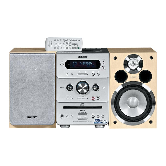
SERVICE MANUAL
Ver 1.0 2004.04
• CMT-GPX6/GPX7 are composed of the following models.
As service manuals are issued for each component model, please refer to them.
COMPONENT MODEL NAME
COMPACT DISC DECK RECEIVER
SPEAKER SYSTEM
SPECIFICATIONS
Power requirements
North American model:
120 V AC, 60 Hz
European model:
230 V AC, 50/60 Hz
Korean model:
220 V AC, 60 Hz
Argentina model:
220 V AC, 50 Hz
230 − 240 V AC, 50/60 Hz
Australian model:
110 − 120 V or 220 – 240 V
Other models:
AC, 50/60 Hz
Adjustable with voltage
selector
Power consumption
CMT-GPX7:
105 W
0.25 W (in Power Saving
Mode)
CMT-GPX6:
80 W
Approx. 181.5 × 261.5 ×
Dimensions (w/h/d)
357.5 mm incl. projecting
parts and controls
Mass
CMT-GPX7:
Approx. 6.3 kg
CMT-GPX6:
Approx. 5.8 kg
Supplied accessories
Remote Commander (1)
R6 (size AA) batteries (2)
AM loop antenna (1)
FM lead antenna (1)
Design and specifications are subject to change
without notice.
Sony Corporation
9-877-741-01
2004D05-1
Home Audio Company
© 2004.04
Published by Sony Engineering Corporation
CMT-GPX6/GPX7
CMT-GPX6
HCD-GPX6
SS-CGPX6
ACCESSORIES
Part No.
1-478-518-11 COMMANDER, STANDARD (RM-SC3)
1-754-102-31 ANTENNA, ROOP (LW.MW)
1-754-243-11 ANTENNA (FM)
4-253-903-12 MANUAL, INSTRUCTION (ENGLISH) (US, SP, HK, AUS, AEP, AR)
4-253-903-21 MANUAL, INSTRUCTION (FRENCH, SPANISH) (SP, AEP, AR)
4-253-903-31 MANUAL, INSTRUCTION (GERMAN, DUTCH, ITALIAN) (AEP)
4-253-903-41 MANUAL, INSTRUCTION (SWEDISH, POLISH) (AEP)
4-253-903-51 MANUAL, INSTRUCTION (TRADITIONAL CHINESE) (SP, HK)
4-253-903-61 MANUAL, INSTRUCTION (KOREAN) (KR)
4-253-903-71 MANUAL, INSTRUCTION (ARABIC) (SP)
4-253-904-11 MANUAL, INSTRUCTION (DANISH, FINNISH) (AEP)
4-253-904-21 MANUAL, INSTRUCTION (PORTUGUESE) (AEP)
4-253-904-31 MANUAL, INSTRUCTION (RUSSIAN) (AEP)
4-253-904-41 MANUAL, INSTRUCTION (GREEK) (AEP)
4-253-904-51 MANUAL, INSTRUCTION (HUNGARIAN, CZECH) (AEP)
4-253-904-61 MANUAL, INSTRUCTION (SLOVAKIAN) (AEP)
4-253-904-71 MANUAL, INSTRUCTION (TURKISH) (AEP)
•Abbreviation
AR
AUS : Australian model
HK
MICRO Hi-Fi COMPONENT SYSTEM
Australian Model
CMT-GPX7
HCD-GPX7
SS-CGPX7
Description
: Argentina model
: Hong Kong model
US Model
CMT-GPX6
AEP Model
CMT-GPX7
E Model
CMT-GPX6/GPX7
Remark
KR
: Korean model
SP
: Singapore model
Advertisement
Table of Contents

Related Manuals for Sony SS-CGPX7


Summarization of Contents
SPECIFICATIONS
AUDIO POWER SPECIFICATIONS
Details output power and total harmonic distortion for amplifier sections.
COMPONENT SPECIFICATIONS
Covers CD player, tape deck, and tuner section specifications.
GENERAL SPECIFICATIONS
Includes power requirements, consumption, dimensions, and mass.
ACCESSORIES
SUPPLIED ACCESSORIES
Lists items included with the unit, such as remote commander and batteries.
REVISION HISTORY
REVISION LOG
Records changes made to the service manual across different versions.
SAFETY AND HANDLING
SAFETY CHECK-OUT PROCEDURES
Outlines essential safety checks after service, including AC leakage tests.
UNLEADED SOLDER INFORMATION
Provides guidance on characteristics and handling of unleaded solder.
SERVICING NOTES
OPTICAL PICK-UP HANDLING
Advises on precautions for handling optical pick-up blocks to prevent electrostatic damage.
LASER DIODE CHECKS
Explains procedures for checking laser diode emission and focus search operation.
GENERAL INFORMATION
LOCATION OF CONTROLS
Identifies and describes the main unit and remote control buttons and features.
REMOTE CONTROL OPERATIONS
CLOCK SETTING PROCEDURE
Details steps for setting and adjusting the system's clock using the remote control.
DISASSEMBLY PROCEDURES
DISASSEMBLY FLOW CHART
Provides a step-by-step guide for disassembling the main unit.
COMPONENT DISASSEMBLY
Illustrates the disassembly of key components like side plates, top block, and front panel.
TEST MODES
TEST MODE ENTRY AND OPERATION
Explains how to enter and operate various test modes like MC Cold Reset and Common Test Mode.
SPECIFIC TEST MODE FUNCTIONS
Describes functions for CD repeat cancellation, CD ship mode, CD slot lock, and others.
ELECTRICAL ADJUSTMENTS
DECK SECTION ADJUSTMENTS
Details adjustments for the deck section, including REC BIAS adjustment.
CD SECTION ADJUSTMENTS
Covers adjustments for the CD section, such as S-curve and RFAC level checks.
DIAGRAMS AND SCHEMATICS
BLOCK DIAGRAMS
Presents block diagrams for CD Servo, Main, and Panel/Power Supply sections.
PRINTED WIRING BOARDS
Shows the layout of printed wiring for CD, Driver, Main, AMP, and Panel boards.
IC BLOCK DIAGRAMS
MAJOR IC FUNCTIONAL DIAGRAMS
Illustrates the internal block diagrams and pin functions of key ICs used in the unit.
EXPLODED VIEWS
UNIT EXPLODED VIEWS
Provides exploded views of the main unit components like side plates, front panel, and chassis.
CD MECHANISM EXPLODED VIEWS
Shows exploded views of the CD mechanism deck sections.
ELECTRICAL PARTS LIST
AMP BOARD PARTS LIST
Lists all components used on the Amplifier board, including ICs, transistors, and resistors.
COMPONENT LISTINGS
Details capacitors, diodes, resistors, connectors, and fuses used throughout the unit.
Need help?
Do you have a question about the SS-CGPX7 and is the answer not in the manual?
Questions and answers