Table of Contents
Advertisement
Quick Links
P
V
RO
U
Instruction Manual
• 0-20 mA, 4-20 mA, 0-5 V, 1-5 V, and ±10 V Inputs
• Start, Batch, Pause, & Stop with Front Panel Buttons
• Display Batch Total + Rate, Grand Total, Batch Count or Preset
• Single or Multi-Stage Batching with up to 8 Relays
• Automatic Overflow Protection
• Manual Control or Automatic Batching
• Dual-Line Display
• NEMA 4X and IP65 Rated Front Panel
• UL Listed & CE Marked
• Display Features 0.6" & 0.46" Digits
• Six Full Digits on Each Line
• Optional Superluminous Sunlight Readable Display
• Free USB Programming Software & Cable
• 2 or 4 Relays + Isolated 4-20 mA Output Options
• External 4-Relay & Digital I/O Expansion Modules
• Input Power Options Include 85-265 VAC or 12-24 VDC
• Isolated 24 VDC @ 200 mA Transmitter Power Supply
• Modbus® RTU Communication Protocol Standard
PRECISION DIGITAL CORPORATION
233 South Street • Hopkinton MA 01748 USA
Tel (800) 343-1001 • Fax (508) 655-8990
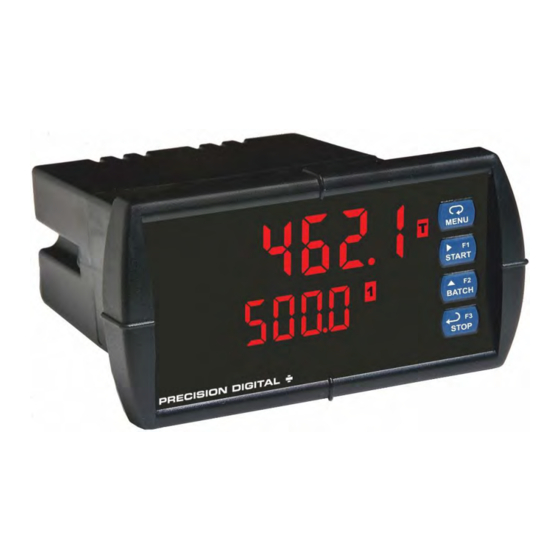
PD6210 Analog Input Batch Controller
USB Install
Batch Controller
www.predig.com
Advertisement
Table of Contents
Troubleshooting

Related Manuals for PRECISION DIGITAL PDA2811


Summarization of Contents
Disclaimer and Warranty Information
Disclaimer
Information subject to change, no warranties expressed or implied, and disclaims liability for improper use.
Limited Warranty
Warrants product against defects in material or workmanship for a specified period, liability limited to purchase value or repair.
Registered Trademarks
Lists registered trademarks of Precision Digital Corporation and other companies mentioned in the document.
Specifications Overview
Process Input Specifications
Details the selectable input types (current, voltage, Modbus) and their respective ranges and accuracy.
Relay Specifications
Describes relay types, ratings, assignments (batch control, alarms, sampling), preclose, and fail-safe operation.
Modbus RTU Serial Communications
Details Modbus RTU serial communication parameters such as Slave ID, Baud Rate, Transmit Time Delay, Data, and Parity.
PDA1044 Digital I/O Expansion Module
Describes the specifications for the PDA1044 module, including channels, digital input/output logic, and current ratings.
Safety and Installation
Safety Information
Provides essential safety warnings regarding hazardous voltages, installation, and operation of the controller.
Panel Mounting Instructions
Detailed steps for preparing the panel cutout, mounting the controller, and securing it properly.
Mounting Dimensions and Transmitter Supply
Mounting Dimensions
Provides side and top view dimensions of the controller, including clearance requirements for installation.
Transmitter Supply Voltage Selection
Explains how to configure the internal jumper J4 to select the desired excitation voltage (5, 10, or 24 VDC) for the transmitter.
Electrical Connections
Connectors Labeling
Shows the location of connectors on a fully loaded PD6210 controller based on requested configuration.
Power Connections
Describes how to connect power to the controller, including fuse requirements and polarity.
Relay and Serial Communications
Modbus RTU Serial Communications
Explains how to connect for serial communications using RJ45 port and optional adapters like PDA1232 or PDA1485.
Relay Connections
Details how to connect relays to the controller, distinguishing C terminals from the SIGNAL connector's COM.
Switching Inductive Loads
Recommends using suppressors (RC networks) for switching inductive loads to protect the microprocessor and prolong relay life.
Digital Input and Analog Output Connections
F4 Digital Input Connections
Describes how to connect a digital input to the F4 terminal, specifying normally open closure or active low signal.
4-20 mA Output Connections
Explains how to connect the 4-20 mA transmitter output to external devices, powered internally or externally.
Analog Output Transmitter Power Supply
Details the use of the internal 24 VDC supply for the analog output or other devices when the analog output is not used.
Expansion Modules and Interlock Feature
External Relay & Digital I/O Connections
Details connecting expansion modules (PDA1004, PDA1044) using CAT5 cables and the importance of module recognition.
Interlock Relay Feature
Explains how to reassign alarm/control relays as interlock relays and wire them to digital inputs for safety control.
Basic Operation and Programming
Front Panel Buttons and Status LED Indicators
Details the function of each front panel button (Menu, Start, Batch, Stop) and the meaning of the status LEDs.
Programming Procedures
Outlines the steps for programming the controller using the front panel buttons: Menu, arrow keys, and Enter.
Controller Operation
Default Batch Control Operation
Explains the default operation of the START, BATCH, and STOP buttons for initiating, programming, and controlling a batch process.
MeterView Pro Software
MeterView Pro Installation
Step-by-step guide for installing the MeterView Pro software and connecting the meter via USB.
Menu Navigation and Numeric Input
Main Menu Map
Diagram illustrating the flow of the main menu, including Setup, Reset, Control, and Password sections.
Setting Numeric Values
Explains how to set numeric values using the front panel buttons (arrow keys, Enter) for digits and decimal points.
Scaling and Calibration Procedures
Setting the Input Signal
Instructions for selecting current or voltage input signals and their respective ranges (0-20mA, ±10V).
Setting Totalizer and Batching Features
Enables or disables totalizer and batching features, with batch control being default and required for most batching functions.
Setting Input Units or Custom Tags
Explains how to select display units or custom tags for rate, total, or grand total using a 7-segment character set.
Programming the Batch Controller
Input Calibration Method
Describes three methods for calibrating/scaling: Factor, Scale (without source), and Calibrate (with source).
Scaling the Controller
Error Message Interpretation
Explains error messages during scaling/calibration and lists common causes like incorrect connections or span issues.
Total Settings and Calibration
Batch Start Mode
Explains manual and automatic batch start modes, including automatic restart delay after a completed batch.
Calibrating with External Source
Guides on calibrating the controller by applying an input signal and corresponding display value, recommending a calibrated signal source.
Relay Configuration Details
Relay Assignment
Details how to assign relays to parameters like rate alarms, batch control total, or grand total alarms.
Setting the Relay Action
Explains different relay action modes: Auto, Sampling, Off, manual reset, latching, and pump alternation control.
Setting Batch Control Relays
Describes assigning relays to 'total' for batch control and enabling multi-stage batching with preclose options.
Alarm and Fail-Safe Settings
Programming Alarm Set and Reset Points
How to program set points for high/low alarms and reset points, including deadband calculation.
Setting Fail-Safe Operation
Explains how to enable or disable fail-safe operation for relays, noting it's not for batch relays assigned to total.
Programming Time Delay
Details programming On and Off time delays for relays, which affect transfer state after condition is maintained.
Relay Operation Details and LEDs
Relays Initialization
Describes how batch control relays activate on START, rate alarms on batch start, and grand total alarms on power-up.
Front Panel LEDs
Explains the function of the four alarm points and their corresponding front panel LEDs for status indication.
Relay Operation Modes
Automatic Reset Operation
Details automatic reset for relays where acknowledgment has no effect, and the relay resets when the alarm condition clears.
Interlock Relay Feature Setup
Guides on setting up interlock relays by assigning action to 'off' and using digital inputs to force relays on.
Sample Relay Operations
Sample Relay Operation
Explains how a sampling relay activates for a set time when a rate or total set point is reached.
Relay and Alarm Operation Diagrams
Illustrates common relay operations (High/Low Alarm, Fail-Safe) with graphs showing input, relay, and LED status.
Advanced Relay Operations
Rate Relay Sampling Operation
Details how rate sampling relays activate for a programmed time when the set point rate is reached.
Total Relay Sampling Operation
Explains total sampling relays activating for a set time when the programmed batch total set point is reached.
Signal Loss or Loop Break Relay Operation
Shows how relays react to 4-20mA loop breaks (Turn On, Turn Off, Ignore) for high alarm relays.
Time Delay and Analog Output Scaling
Time Delay Operation
Illustrates the operation of time delay functions, showing how relays trip after On or Off delays based on input signals.
Scaling the 4-20 mA Analog Output
Explains how to scale the 4-20 mA analog output to any rate display range by programming display values to mA output signals.
Control and Security Settings
Reset Menu
Allows resetting total, grand totals, batch count, max, or min readings, with options for 'reset high & low'.
Control Menu
Enables manual control of analog output and relays, overriding input signals, with an 'M' LED indicating Manual mode.
Setting Up the Password
Details programming three security levels and total/grand total password protection to prevent unauthorized changes.
Password Protection and Access
Grand Total Reset Password & Non-Resettable Total
Explains password protection for grand total resets and the non-resettable total feature, which cannot be disabled once set.
Accessing Password Protected Controller
Describes how to access menus on a password-protected controller by entering the correct password.
Disabling Password Protection
Provides instructions on how to disable password protection by entering the correct password twice.
Advanced Operation and Programming
Advanced Features Menu
Explains how to access the advanced features menu by holding the Menu button for three seconds.
Function Keys and Advanced Setup
Function Keys Operation
Details the default settings and actions for programmable function keys (F1-F3) and the digital input F4.
Multi-Point Calibration & Scaling
Explains setting up multi-point calibration/scaling, supporting up to 32 linearization points for enhanced accuracy.
Signal Conditioning and Filtering
Noise Filter Configuration
Details the noise filter function to stabilize unstable signals, allowing adjustment of filter level from 2 to 199.
Noise Filter Bypass
Explains the bypass feature to display abrupt signal changes immediately, setting a minimum bypass value.
Rounding Feature
Describes the rounding feature for displaying steadier values with fluctuating signals, affecting the last two digits.
Modbus RTU Serial Communications
Covers serial communication setup for Modbus RTU protocol, including connection via USB or optional adapters.
Select Menu Options
Signal Conditioning Selection
Details selecting linear, square root, or programmable exponent functions for signal conditioning, including multi-point linearization.
Low-Flow Cutoff
Explains the low-flow cutoff feature to set unsteady outputs to zero, with a programmable cutoff value.
Total Count and Analog Output
Total and Grand Total Count Direction
Allows changing the count direction for batch total and grand total from up to down.
Analog Output Programming
Details programming the 4-20 mA output source, overrange, underrange, break values, and max/min limits.
Programmable Function Keys User Menu
Allows assigning front panel keys (F1-F3) and digital inputs to menus or functions for customized operation.
Troubleshooting and Diagnostics
Diagnostics Menu
Explains accessing the Diagnostics menu to test LEDs, check software version, and manage MeterView Pro installation files.
Reset Controller to Factory Defaults
Provides instructions to load factory default settings via the Advanced Features and Diagnostics menus.
Need help?
Do you have a question about the PDA2811 and is the answer not in the manual?
Questions and answers