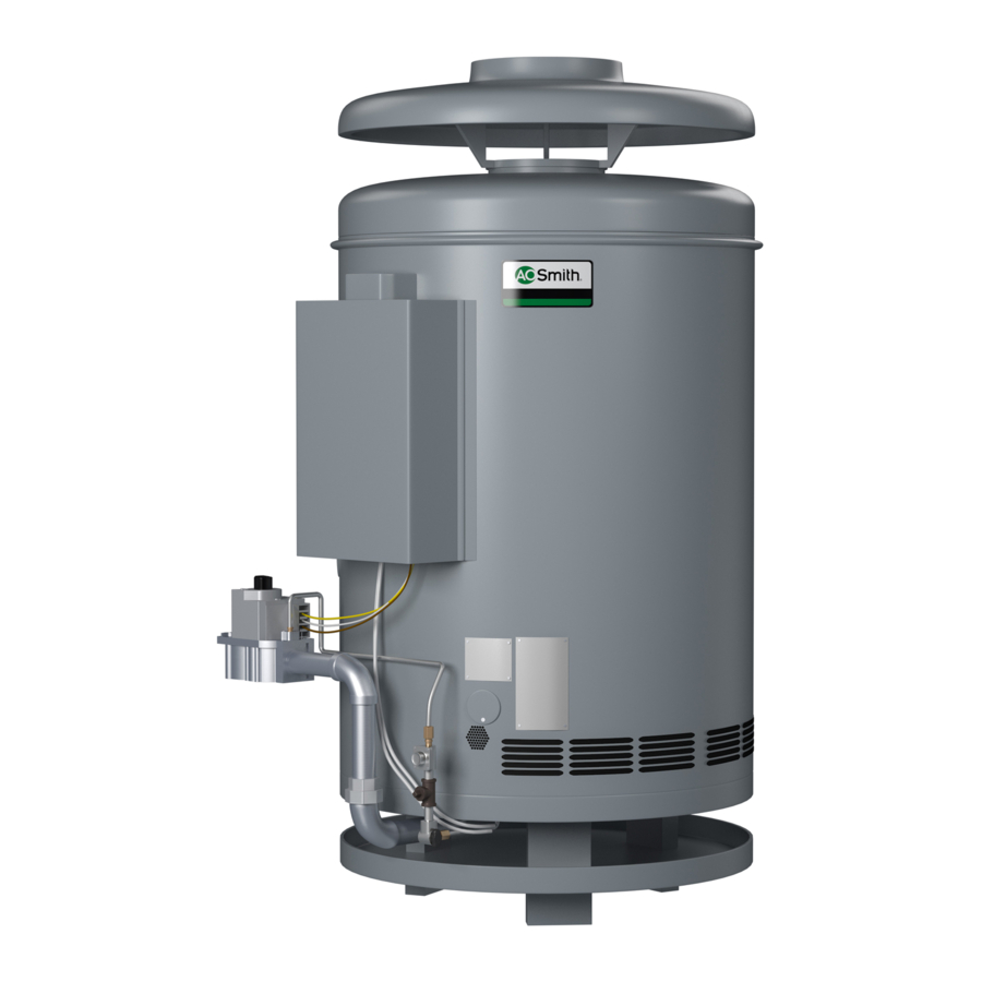
A.O. Smith Burkay HW-300 Installation Operation & Maintenance
Up-flow models gas-fired commercial copper boilers for hydronic heating and hot water supply
Hide thumbs
Also See for Burkay HW-300:
- Instruction manual (62 pages) ,
- Installation & operation manual (56 pages) ,
- User manual (28 pages)
Table of Contents
Advertisement
MODELS HW/HWB 300, 399, 420, 520, 610, 670
GAS-FIRED COMMERCIAL COPPER BOILERS FOR
HYDRONIC HEATING AND HOT WATER SUPPLY
•
INSTALLATION
WARNING: If the information in this manual
is not followed exactly, a fire or explosion
may result causing property damage,
personal injury or death.
— Do not store or use gasoline or other
flammable vapors and liquids in the
vicinity of this or any other appliance.
— WHAT TO DO IF YOU SMELL GAS
• Do not try to light any appliance.
• Do not touch any electrical switch;
do not use any phone in your
building.
• Immediately call your gas supplier
from a neighbor's phone. Follow the
gas supplier's instructions.
• If you cannot reach your gas supplier,
call the fire department.
— Installation and service must be
performed by a qualified installer,
service agency or the gas supplier.
PRINTED IN U.S.A. 0905
UP-FLOW MODELS
•
OPERATION
•
•
INDOOR ONLY
PLACE THESE INSTRUCTIONS ADJACENT TO BOILER AND
NOTIFY OWNER TO KEEP FOR FUTURE REFERENCE
MAINTENANCE
TEXT PRINTED OR OUTLINED IN RED CONTAINS INFORMATION
RELATIVE TO YOUR SAFETY. PLEASE READ THOROUGHLY
BEFORE USING APPLIANCE.
A DIVISION OF A.O. SMITH CORPORATION
MC BEE, SC SEATTLE, WA
VELDHOVEN, THE NETHERLANDS
SUPERSEDES PART NO'S, 210288-000 REV. 01 & 192356-000
1 1 1 1 1
•
LIMITED WARRANTY
CAUTION
STRATFORD, ONTARIO
w w w.hotwater.com
PART NO. 211683-000 REV.02
Advertisement
Table of Contents

Related Manuals for A.O. Smith Burkay HW-300


Summary of Contents for A.O. Smith Burkay HW-300
- Page 1 PLACE THESE INSTRUCTIONS ADJACENT TO BOILER AND NOTIFY OWNER TO KEEP FOR FUTURE REFERENCE 1 1 1 1 1 • LIMITED WARRANTY CAUTION A DIVISION OF A.O. SMITH CORPORATION MC BEE, SC SEATTLE, WA STRATFORD, ONTARIO VELDHOVEN, THE NETHERLANDS w w w.hotwater.com PART NO. 211683-000 REV.02...
-
Page 2: Rough-In Dimensions
Propane 610,000 (179) Ratings shown are for current modern heating system design. Where A.O. Smith boilers are connected to heavy, cast iron radiator systems or where unusual pick-up or large size piping conditions exist, reduce ratings by 10%. NOTE: To compensate for the effects of high altitude areas above 2000 feet, the input, output and heating load ratings should be reduced approximately 4% for each 1000 feet above sea level. -
Page 3: Recovery Capacities - Canadian Models Only
TABLE 3, RECOVERY CAPACITIES - CANADIAN MODELS ONLY Input Temp. (C) Model (Btu/Hr.) Rise (F) HW-300 300,000 5,505 1,455 HW-399 399,000 7,322 1,935 HW-420 420,000 7,708 2,036 HW-520 520,000 9,543 2,521 HW-610 610,000 11,194 7,463 2,958 3,670 2,753 2,202 1,835... -
Page 4: Table Of Contents
FOREWORD CAUTION TEXT PRINTED OR OUTLINED IN RED CONTAINS INFORMATION RELATIVE TO YOUR SAFETY. PLEASE READ THOROUGHLY BEFORE USING APPLIANCE. Detailed installation diagrams are in this manual. These diagrams will serve to provide the installer with a reference for the materials and method of piping suggested. -
Page 5: Location
LOCATION When installing the boiler, consideration must be given to proper location. Location selected should be as close to the stack or chimney as practicable with adequate air supply and as centralized with the piping system as possible. This location should also be such that the gas ignition system components are protected from water (dripping, spraying, etc.) during appliance operation and service (circulator replacement, control replacement, etc.). -
Page 6: Chemical Vapor Corrosion
Where an exhaust fan is installed in the same room with a boiler, sufficient openings for air must be provided in the walls. UNDERSIZED OPENINGS WILL CAUSE AIR TO BE DRAWN INTO THE ROOM THROUGH THE CHIMNEY, CAUSING POOR COMBUSTION. SOOTING MAY RESULT WITH AN INCREASED RISK OF ASPHYXIATION. - Page 7 A. O. Smith copper heat exchanger boilers are covered below. Conventional 10 C (20 F) drop in systems for a fully loaded boiler will maintain the following approximate flow rates: U.S. CANADIAN MODELS MODELS HW-300 HWB-300 HW-399 HWB-399 HW-420 HWB-420 HW-520 HWB-520 HW-670 HWB-610...
- Page 8 BOILER INLET - OUTLET SIZES HWB-300 - 1-1/4", HWB-399 - 1-1/2", HWB-420-1-1/2", HWB-520 & HWB-610 - 2". Canadian Models HW-300 - 1-1/4", HW-399 - 1-1/2", HW-420-1-1/2", HW-520 & HW-670 - 2". U.S. Models MINIMUM BRANCH SIZES TO BOILERS HWB-300 - 1-1/4"...
-
Page 9: Gas Connections
2-1/2" (64mm) diameter are suggested on HWB/HW-399, HWB/HW-420, HWB/HW-520, HWB/HW-610 and HW-670 units. HWB/HW-300 units should have 1-1/2" (38mm) diameter manifolds. The circuits should be spaced on the header at a minimum of 3"... -
Page 10: Installation Codes
IT IS IMPORTANT TO GUARD AGAINST GAS VALVE FOULING FROM CONTAMINANTS IN THE GAS WAYS. SUCH FOULING MAY CAUSE IMPROPER OPERATION, FIRE OR EXPLOSION. IF COPPER SUPPLY LINES ARE USED THEY MUST BE CERTIFIED FOR GAS SERVICE. BEFORE ATTACHING THE GAS LINE BE SURE THAT ALL GAS PIPE IS CLEAN ON THE INSIDE. -
Page 11: Gas Pressure Regulators
14" W.C. (1/2 P.S.I.). If higher gas pressures are encountered, a service regulator is necessary. TABLE 8 CORRECT MANIFOLD PRESSURE FOR FULL BOILER INPUT (IN INCHES OF WATER COLUMN) Model Rated Number Input HWB/HW-300 300,000 HWB/HW-399 399,000 HWB/HW-420 420,000 HWB/HW-520 520,000 HWB/HW-610 610,000 HW-670 Nat. -
Page 12: Venting The Boiler - Standard Venting
FOLLOWED. ® ROBERTSHAW 7000 DERHC HWB/HW-300, 399,-420, -520, -610, -670 NATURAL GAS WITH I.I.D. HW-300, -399, -420, -520, -670 LP GAS WITH I.I.D. U.S. ONLY ® ROBERTSHAW 7000 ERHC (LP) HWB/HW-300, 399,-420, -520, -610 SINGLE STAGE STANDING PILOT, CANADIAN ONLY... - Page 13 Where a continuous or intermittent back draft is found to exist the cause must be determined and corrected. A special vent cap may be required. If the back draft cannot be corrected by the normal methods or if a suitable draft cannot be obtained, a blower type flue gas exhauster may be employed to ensure proper venting and correct combustion if permitted by local codes.
- Page 14 TABLE 9, COMBINED VENT SIZING TABLES MODEL HW/HWB-300 BOILER Input: 300,000 Btuh Required Connector or Smoke Pipe Diameter Connector Total Vent Height(Measured in Feet Above Draft Hood) Rise in Feet Connector Diameter (in Inches) 4 or more Number Total Total Vent Height(Measured in Feet Above Draft Hood) if Units Input Combined...
-
Page 15: Venting Maintenance - Standard Venting
(OPTIONAL) POWER VENT SYSTEM If you are installing the optional Power Vent Kit, refer to your HWB/HW Power Vent Kit Installation Instructions for proper wiring and installation procedures. Contact your local A.O. Smith representative for details. VENTING SYSTEM HAVE VENTING SYSTEM CHECKED EVERY SIX MONTHS FOR OBSTRUCTIONS AND/OR DETERIORATION IN VENT PIPING. -
Page 16: Wiring Connections
The storage tank temperature and pressure (T & P) relief valve must comply with the applicable construction provisions of the Standard for Relief Valves and Automatic Gas Shutoff Devices for Hot Water Supply Systems, Z21.22 and/or CAN1-4.4. The T & P valve must be of the automatic reset type and not embody a single-use type fusible plug, cartridge or linkage. - Page 17 HWB & HW-300, -399, -420, -500 & -610 (NATURAL GAS) SINGLE STAGE I.I.D. - ROBERTSHAW ® GAS VALVE HWB & HW-300, -399, -420, -520, -610 (NATURAL GAS ONLY) - CANADIAN MODELS FIGURE 10 ® Robertshaw is a registered trademark of Fulton Controls Corp.
- Page 18 CONNECTION DIAGRAM HWB, HW-420,-520, -610 (PROPANE GAS) SINGLE STAGE PROPANE - ROBERTSHAW GAS VALVE 24 VOLT -HW, HWB-420, -520, -610 CANADIAN MODELS FIGURE 11...
- Page 19 CONNECTION DIAGRAM HWB & HW 300, 399 (PROPANE GAS) FIGURE 13 SINGLE STAGE PROPANE ROBERTSHAW GAS VALVE 24 VOLT - HWB, HW-300, 399 CANADIAN MODELS FIGURE 11A...
- Page 20 HW-300, HW-399, HW-420, HW-500 & HW-670 (NATURAL GAS) SINGLE STAGE I.I.D. - ROBERTSHAW GAS VALVE HW-300, -399, -420, -520 & 670 (NATURAL GAS ONLY) - U.S. MODELS FIGURE 11B...
- Page 21 HW-300, HW-399, HW-420, HW-500 & HW-670 (PROPANE GAS) FIGURE 12 SINGLE STAGE I.I.D. - ROBERTSHAW GAS VALVE HW-300, -399, -420, -520 & 670 (PROPANE GAS ONLY) - U.S. MODELS FIGURE 11C...
- Page 22 THESE LAYOUTS ARE NOT WIRING DIAGRAMS. A.O. Smith offers accessory Sequencing Control Panels; TEK-252 for 2 Stage Boiler Control TEK-254 for 4 Stage Boiler Control TEK-258 for 8 stage Boiler Control For more information contact A.O. Smith Product Service Department at 1-800-433-2545.
- Page 23 NOTE: Building temperature controls supply electric power to building circulator. Main flow switch proves main water flow before energizing sequencing and resetting controls. CONTROL APPLICATION DIAGRAM - TWO BOILER LINEAR-TEMP® INSTALLATION WITH TWO CIRCULATORS NOTE: Building temperature controls supply electric power to building circulator.
- Page 24 NOTE: Building temperature controls supply electric power to building circulator. Main flow switch proves main water flow before energizing sequencing and resetting controls. Outdoor thermostat required if building controls do not provide automatic shutdown of reset controls during warm weather. Boilers and Secondary Circulator are Controlled by Dual Bulb, Dual Switch Controller...
- Page 25 CER-TEMP 80 - 1 UNIT INSTALLATION - FOR HOT WATER SUPPLY APPLICATION CANADIAN MODELS, JUNCTION BOX W/6 TERMINALS CER-TEMP 80 - 1 UNIT INSTALLATION U.S. MODELS, JUCNTION BOX W/4 TERMINALS FIGURE 17 FOR HOT WATER SUPPLY APPLICATION FIGURE 18 FIGURE 19...
- Page 26 CER-TEMP 80 - 2 OR 3 UNIT INSTALLATION - FOR HOT WATER SUPPLY APPLICATION CANADIAN MODELS, JUNCTION BOX W/6 TERMINALS FIGURE 20...
- Page 27 SCHEMATIC CANADIAN MODELS, JUNCTION BOX W/6 TERMINALS FIGURE 21...
- Page 28 CER-TEMP 80 - 2 OR 3 UNIT INSTALLATION CONNECTION DIAGRAM (FOR HOT WATER SUPPLY APPLICATION) U.S. MODELS, JUNCTION BOX W/4 TERMINALS FIGURE 22...
- Page 29 CER-TEMP 80 - 2 OR 3 UNIT INSTALLATION SCHEMATIC DIAGRAM (FOR HOT WATER SUPPLY APPLICATION) U.S. MODELS, JUNCTION BOX W/4 TERMINALS FIGURE 23...
- Page 30 BOOSTER - RECOVERY WIRING DIAGRAM CANADIAN MODELS, JUNCTION BOX W/6 TERMINALS FIGURE 24 SHURE-TEMP BOOSTER - RECOVERY WIRING DIAGRAM (TWO TEMPERATURE SYSTEM) CANADIAN MODELS, JUNCTION BOX W/6 TERMINALS FIGURE 25...
- Page 31 BOOSTER - RECOVERY WIRING DIAGRAM U.S. MODELS, JUNCTION BOX W/4 TERMINALS FIGURE 26 SHURE - TEMP BOOSTER - RECOVERY WIRING DIAGRAM TWO-TEMPERATURE SYSTEM U.S. MODELS, JUNCTION BOX W/4 TERMINALS FIGURE 27...
-
Page 32: Water Line Connections
WATER LINE CONNECTIONS This section provides detailed installation diagrams for typical methods of application for the unit using a Cer-Temp 80 Recovery System (for one temperature water), and either Booster-Recovery or the Shure-Temp Booster-Recovery System (for two temperature water). These diagrams will serve to provide the installer with a reference for the materials and methods of piping necessary for installation. -
Page 33: Tank Temperature Control
Temperature Time to Produce 2nd & 3rd Setting Degree Burns on Adult Skin OVER: 170°F (77°C) Nearly instantaneous 160°F (71°C) About 1/2 second 150°F (65°C) About 1-1/2 seconds 140°F (60°C) Less than 5 seconds 130°F (54°C) About 30 seconds 120°F (49°C) More than 5 minutes USE ANTI-SCALD VALVE(S) in the hot water system to reduce the risks of scalds at points of use such as lavatories, sinks and... -
Page 34: Piping Diagrams
ONE HW-300, HW-399, HW-420, HW-520, HW-610 OR ONE HW-670 UP-FLOW MODEL IMPORTANT THE INSTALLATION OF SAFETY FLOW SWITCH AS SHOWN IS REQUIRED TO PROTECT THE BOILER IN CASE OF WATER SERVICE INTERRUPTION OR CIRCULATOR FAILURE (A.O. SMITH PKG. NO. 211480). - Page 35 ONE HW-300, HW-399, HW-420, HW-520, HW-610 OR ONE HW-670 UP-FLOW MODEL IMPORTANT THE INSTALLATION OF SAFETY FLOW SWITCH AS SHOWN IS REQUIRED TO PROTECT THE BOILER IN CASE OF WATER SERVICE INTERRUPTION OR CIRCULATOR FAILURE (A.O. SMITH PKG. NO. 211480).
- Page 36 THE INSTALLATION OF SAFETY FLOW SWITCH AS SHOWN IS REQUIRED TO PROTECT THE BOILER IN CASE OF WATER SERVICE INTERRUPTION OR CIRCULATOR FAILURE (A.O. SMITH PKG. NO. 211480). PIPING AND FITTINGS BETWEEN GATE VALVES AND BOILERS SHOULD BE BRASS OR BRONZE. OTHER PIPING SHOULD CONFORM TO LOCAL CODES.
- Page 37 TWO HW-300's, HW-399's, HW-420's, HW-520's, HW-610's OR HW-670's UP-FLOW MODEL IMPORTANT THE INSTALLATION OF SAFETY FLOW SWITCH AS SHOWN IS REQUIRED TO PROTECT THE BOILER IN CASE OF WATER SERVICE INTERRUPTION OR CIRCULATOR FAILURE (A.O. SMITH PKG. NO.211480). PIPING AND FITTINGS BETWEEN GATE VALVES AND BOILERS SHOULD BE BRASS OR BRONZE.
- Page 38 THE INSTALLATION OF SAFETY FLOW SWITCH AS SHOWN IS REQUIRED TO PROTECT THE BOILER IN CASE OF WATER SERVICE INTERRUPTION OR CIRCULATOR FAILURE (A.O. SMITH PKG. NO. 211480). PIPING AND FITTINGS BETWEEN GATE VALVES AND BOILERS SHOULD BE BRASS OR BRONZE. OTHER PIPING SHOULD CONFORM TO LOCAL CODES.
- Page 39 THE INSTALLATION OF SAFETY FLOW SWITCH AS SHOWN IS REQUIRED TO PROTECT THE BOILER IN CASE OF WATER SERVICE INTERRUPTION OR CIRCULATOR FAILURE (A.O. SMITH PKG. NO. 211480). PIPING AND FITTINGS BETWEEN GATE VALVES AND BOILERS SHOULD BE BRASS OR BRONZE. OTHER PIPING SHOULD CONFORM TO LOCAL CODES.
- Page 40 TWO TEMPERATURE SYSTEM WITHOUT RECIRCULATION ONE HW-300, HW-399, HW-420, HW-520, HW-610 OR HW-670 UP-FLOW MODEL DANGER TEMPERATURE SETTING SHOULD NOT EXCEED SAFE USE TEMPERATURE AT FIXTURES. SEE TANK TEMPERATURE CONTROL WARNING ON PAGE 32. IF HIGHER PREHEAT TEMPERATURES ARE NECESSARY TO OBTAIN ADEQUATE BOOSTER OUTPUT, ADD AN ANTI-SCALD VALVE FOR HOT WATER SUPPLIED TO FIXTURES.
- Page 41 ONE HW-300, HW-399, HW-420, HW-520, HW-610 OR HW-670 UP-FLOW MODEL DANGER TEMPERATURE SETTING SHOULD NOT EXCEED SAFE USE TEMPERATURE AT FIXTURES. SEE TANK TEMPERATURE CONTROL WARNING ON PAGE 32. IF HIGHER PREHEAT TEMPERATURES ARE NECESSARY TO OBTAIN ADEQUATE BOOSTER OUTPUT, ADD AN ANTI-SCALD VALVE FOR HOT WATER SUPPLIED TO FIXTURES.
- Page 42 BOOSTER RECOVERY SYSTEM (PATENTED) - TWO TEMPERATURE SYSTEM WITHOUT RECIRCULATION ONE HW-300, HW-399, HW-420, HW-520, HW-610 OR HW-670 UP-FLOW MODEL DANGER TEMPERATURE SETTING SHOULD NOT EXCEED SAFE USE TEMPERATURE AT FIXTURES. SEE TANK TEMPERATURE CONTROL WARNING ON PAGE 32. IF...
- Page 43 TWO TEMPERATURE SYSTEM WITHOUT RECIRCULATION ONE HW-300, HW-399, HW-420, HW-520,HW-610 OR HW-670 UP-FLOW MODEL COMMERCIAL BOILER WITH VERTICAL TANK DANGER TEMPERATURE SETTING SHOULD NOT EXCEED SAFE USE TEMPERATURE AT FIXTURES. SEE TANK TEMPERATURE CONTROL WARNING ON PAGE 32. IF HIGHER PREHEAT TEMPERATURES ARE NECESSARY TO OBTAIN ADEQUATE BOOSTER OUTPUT, ADD AN ANTI-SCALD VALVE FOR HOT WATER SUPPLIED TO FIXTURES.
- Page 44 WITH TWO VERTICAL TANKS WITH THREE VERTICAL TANKS FIGURE 39 DANGER TEMPERATURE SETTING SHOULD NOT EXCEED SAFE USE TEMPERATURE AT FIXTURES. SEE TANK TEMPERATURE CONTROL WARNING ON PAGE 32. IF HIGHER PREHEAT TEMPERATURES ARE NECESSARY TO OBTAIN ADEQUATE BOOSTER OUTPUT, ADD AN ANTI-SCALD VALVE FOR HOT WATER SUPPLIED TO FIXTURES.
-
Page 45: Start-Up And Operating Instructions
DANGER TEMPERATURE SETTING SHOULD NOT EXCEED SAFE USE TEMPERATURE AT FIXTURES. SEE TANK TEMPERATURE CONTROL WARNING ON PAGE 32. IF HIGHER PREHEAT TEMPERATURES ARE NECESSARY TO OBTAIN ADEQUATE BOOSTER OUTPUT, ADD AN ANTI-SCALD VALVE FOR HOT WATER SUPPLIED TO FIXTURES. START-UP AND OPERATING INSTRUCTIONS WARNING After placing boiler into operation, the ignition system safety shutoff... -
Page 46: Filling And Venting
IMPORTANT IT IS RECOMMENDED THAT A QUALIFIED PERSON PERFORM THE INITIAL FIRING OF THE BOILER. AT THIS TIME THE USER SHOULD NOT HESITATE TO ASK THE INDIVIDUAL ANY QUESTIONS WHICH HE MAY HAVE IN REGARD TO THE OPERATION AND MAINTENANCE OF THE UNIT. FILLING AND VENTING Fast fill system through bypass until pressure approaches desired system pressure. - Page 47 LIGHTING AND OPERATING INSTRUCTIONS (NATURAL AND PROPANE GAS WITH I.I.D.) FOR YOUR SAFETY READ BEFORE OPERATING WARNING EXACTLY. A FIRE OR EXPLOSION MAY RESULT CAUSING PROPERTY DAMAGE, PERSONAL INJURY OR LOSS OF LIFE. WARNING: HOT WATER CAN PRODUCE 3rd DEGREE BURNS IN 6 SECONDS AT 140°...
-
Page 48: Lighting Instructions
LIGHTING AND OPERATING INSTRUCTIONS PROPANE (LP) STANDING PILOT MODELS FOR YOUR SAFETY READ BEFORE LIGHTING WARNING: IF YOU DO NOT FOLLOW THESE INSTRUCTIONS EXACTLY. A FIRE OR EXPLOSION MAY RESULT CAUSING PROPERTY DAMAGE, PERSONAL INJURY OR LOSS OF LIFE. WARNING: HOT WATER CAN PRODUCE 3rd DEGREE BURNS IN 6 SECONDS AT 140°... - Page 49 (Continued from Page 46) 4. Adjust pilot flame. To adjust the pilot flame, remove the cap screw from the pilot adjusting valve and turn to deliver a sufficient flame at the pilot burner to cover 3/8" to 1/2" (10-12mm) of the sensing probe tip.
- Page 50 FIGURE 43D The purpose of checking the current ahead and after the protector switch is to measure the millivolt drop across the contacts. This drop should be between 4 and 6 millivolts. PROTECTOR SWITCH CONTINUITY TEST Do not depress the protector switch reset button prior to testing. The leads from the switch are removed from the thermocouple function block and attached to the leads from a test flashlight.
-
Page 51: Electronic Intermittent Pilot Ignition Control
The inlet gas pressure must not exceed or be less than the values shown on rating plate. CONTROL SETTINGS MODEL HW-300, HW-399, HW-420, HW-520, HW-610 & HW-670 The high limit is a safety device wired in series with the ignition system. Set the high limit control to approximately 10 maximum designed system temperature. -
Page 52: High Altitude Installations
NORMAL OPERATING SEQUENCE WITH INTERMITTENT IGNITION CONTROLS (I.I.D.) System control calls for boiler operation. Spark begins at pilot burner. Pilot gas control valve is energized. Gas flows to pilot burner. Pilot burner gas ignites. The sensing probe on the pilot burner senses the presence of the pilot flame. -
Page 53: Pressure Reducing Valve
The arrow on the side case must point in the direction of the flow. TABLE 11 - SAFETY FLOW SWITCH Minimum Pipe Rate Contacts Closed Model (Flow) Number HWB/HW-300 HWB/HW-399 HWB/HW-420 HWB/HW-520 13.7 HWB/HW-610/670 13.7 The safety flow switch may be field adjusted to obtain higher minimum flow rates than those shown in table 11. -
Page 54: Safety Relief Valve Maintenance
To adjust the flow rate setting: Remove the flow switch cover. For higher flow rate—turn the range adjusting screw clockwise. For lower flow rate—turn the range adjusting screw counter-clockwise. CAUTION The switch is factory set at approximately the minimum flow rate, see Table II. -
Page 55: General Maintenance
GENERAL MAINTENANCE These boilers are designed to give many years of efficient and satisfactory service when properly operated and maintained. To assure continued good performance, recommendations are made. The area around the unit should be kept clean and free from lint and debris. -
Page 56: Deliming Solvents
DELIMING THE HWB/HW BOILER FIGURE 51 MINIMUM AMOUNT OF CLEANING SOLUTION REQUIRED Model Number Litres HWB/HW-300 HWB/HW-399 HWB/HW-420 HWB/HW-520 HWB/HW-610/670 HEAVY LIME DEPOSITS If the solvent does not readily pass through the clogged coils or heat exchanger, it will be necessary to use an acid pump deliming kit, or contact a service agency for proper cleaning. -
Page 57: Pre-Troubleshooting
PRE-TROUBLESHOOTING Before any extensive trouble-shooting, perform the following: Ensure That: — Voltage (120 vac) is supplied to the appliance. — System control (tank temperature control, thermostat, etc.) is calling for appliance operation (call for heat). — Other contacts (switches) are closed (relay, low water cutoff, flow switch, coil protector, pressure switch, etc.). - Page 58 CHECKING HONEYWELL S-8600H OR S-8610M INTERMITTENT IGNITION CONTROLS NO SPARK AT PILOT BURNER Replace ignition module. Turn on gas supply. turn on power supply. Securely connect cable and/or ground wire. Replace pilot burner and/or ground wire. Carefully bend downward top of ground strap to achieve 1/8”...
- Page 59 CHECKING HONEYWELL S8600H OR S-8610M INTERMITTENT IGNITION CONTROLS SPARK AT PILOT BURNER BUT PILOT WILL NOT LIGHT Attach wires firmly. Replace gas valve. Turn on power supply Securely connect cable and/or ground wire. Replace pilot burner Are ignition cable and ground wire in good condition (not brittle, burnt, or cracked)? and/or ground wire.
- Page 60 CHECKING HONEYWELL S-8600H OR S8610M PILOT BURNER LIGHTS BUT MAIN BURNER DOES NOT LIGHT Correct the situation by consulting the installation or user’s manual on how to adjust pilot flame. Replace Is voltage (24 Vac) across terminals ignition MV & MV/PV? module.
- Page 61 CHECKING HONEYWELL S8600H OR S-8610M INTERMITTENT IGNITION CONTROLS NO SPARK AT PILOT BURNER BUT PILOT WILL NOT LIGHT Fix connection and/or tighten module to the appliance Check the circuit providing 24 VAC. Replace ignition module. Turn on gas supply and/ or power supply.
-
Page 62: Limited Warranty
A. O. Smith Corporation, the warrantor, extends the following LIMITED WARRANTY to the owner of this hydronic boiler. If within TEN years after initial installation of the boiler, a heat exchanger, coil or gas burner shall prove upon examination by the warrantor to be defective in material or workmanship, the warrantor, at his option will exchange or repair such part or portion. - Page 64 REPLACEMENT PARTS 5621 W. 115TH STREET, ALSIP, IL 60803 PHONE: 1-800-433-2545 FAX: 1-800-433-2515 E-MAIL: parts@hotwater.com • www.hotwater.com...