Table of Contents
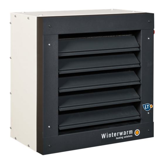
Advertisement
Quick Links
THIS DOCUMENTATION MUST ABSOLUTELY BE READ BEFORE STARTING THE INSTALLATION.
INSTRUCT USER AND LEAVE THIS DOCUMENT WITH HEATER FOR REFERENCE.
Content
1
1.1
1.2
1.3
Matching capacity boiler and WWH
1.4
2
2.1
Table with data
2.2
2.3
3
3.1
3.2
4
4.1
4.2
4.3
4.4
Control with zone valve
5
5.1
5.2
5.3
6
6.1
6.2
Conversion table WWH-110
6.3
Conversion table WWH-115
6.4
Conversion table WWH-120
6.5
Conversion table WWH-230
6.6
Conversion table WWH-235
6.7
Conversion table WWH-245
6.8
Conversion table WWH-350
6.9
Conversion table WWH-365
6.10
Conversion table WWH-380
INSTRUCTION MANUAL
UNIT AIR HEATER
TYPE WWH
GB 402c
Advertisement
Table of Contents

Summary of Contents for Winterwarm WWH 230
-
Page 1: Table Of Contents
INSTRUCTION MANUAL UNIT AIR HEATER TYPE WWH GB 402c THIS DOCUMENTATION MUST ABSOLUTELY BE READ BEFORE STARTING THE INSTALLATION. INSTRUCT USER AND LEAVE THIS DOCUMENT WITH HEATER FOR REFERENCE. Content GENERAL Description Function Matching capacity boiler and WWH Guarantee TECHNICAL FEATURES Table with data User’s restrictions Pre-check... -
Page 2: General
1. General This user’s guide is meant for the installer and if necessary for the user. It’s a reference to operation and installation of the WWH heater. 1.1. Description The WWH is an effective in-direct fired heater. The heat exchanger consist of copper tubes and aluminium fins. This is an approved design for an optimal heat exchange. - Page 3 Type Model size ¾” ¾” ¾” ¾” ¾” 1” 1” 1” 1” 79.5 79.5 79.5 87.5 87.5 74.5 89.5 89.5 87.5 87.5 87.5 89.5 89.5 89.5 342.5 517.5 667.5 Type Unit Heating capacity (90/70) 11,4 14,9 17,6 25,2 32,2 42,7 59,3 72,1 Air output...
-
Page 4: User's Restrictions
2.2. User’s restrictions Work pressure: Max. 5 bar Water temperature: Max. 100⁰C Min. 4⁰C (freezing danger!) Environment temperature: Max. 40⁰C Min. 4⁰C (freezing danger!) Protection grade: IP54 Note: Frost can cause the internal copper tubes in the exchanger to burst, the exchanger will leak. No warranty on this. -
Page 5: Water Connections
The outlet grill can easily be taken off, turned around and replaced, to direct the discharge in any desirable direction. Attention: When replacing the grill, always use the same screws (or screws of same length). A longer screw could pierce the exchanger! See to it that the discharge is not blocked and that the heater has a free suck. -
Page 6: Electrical Connection
4. Electrical connection 4.1 230Vac supply The installation must comply with all applicable local and/or national standards i.e. NEN 1010. There should be a suitable electrical group with a main fuse. There is an electrical diagram further on in this guide. The supply is 230Vac (50 Hz) with earth. - Page 7 4.3.2 Connection with room thermostat combined with contact thermostat This option is applied when the boiler is controlled by its own thermostat and there is a continues hot water supply. Operation: The on/off thermostat will switch when there is heat demand. The contact thermostat will not close (connect) before the water has reached the pre-set temperature.
- Page 8 4.3.4 Combinations with a 5-step switch To reduce the noise level of the WWH, it’s possible to install an optional 5-step switch. This switch will regulate the fan speed of the WWH. Please note that if the fan speed is lower, the heat discharge of the heater will be lower as well.
- Page 9 4.4 Connection with zone valve The zone valve is applied on the WWH when one boiler has to heat several rooms separately. In this situation the zone-valve will control the hot water boiler and hot water supply to the WWH. Operation in short can be summarized as follows: Heat demand is created through the room thermostat.
-
Page 10: Maintenance And Operation
5. Maintenance and operation Causion: Make sure that you have turned off the power group that you are working on. The heater must be earthed. 5.1 Maintenance Especially in dusty spaces, it’s important to clean the heater regularly. If the heat exchanger is heavily covered by dust-traps it will not displace the heat sufficiently. -
Page 11: Water Temperature/ Air Volumes
6. Water temperatures/ air volumes The conversion diagram shows heater capacities in KW under different conditions. These conditions may be: - Water temperature, for example 90/70° C (Regime) - Air temperature sucked by the fan (Air temp) - Turning speed of the fan. When the 5-step switch is applied, the power supplied (voltage) is relevant. - Page 12 6.2 Conversion diagram WWH 110 WWH Heater Instruction manual Pag. 12...
- Page 13 6.2 Conversion diagram WWH 115 WWH Heater Instruction manual Pag. 13...
- Page 14 6.3 Conversion diagram WWH 120 WWH Heater Instruction manual Pag. 14...
- Page 15 6.4 Conversion diagram WWH 230 WWH Heater Instruction manual Pag. 15...
- Page 16 6.5 Conversion diagram WWH 235 WWH Heater Instruction manual Pag. 16...
- Page 17 6.6. Conversion diagram WWH 245 WWH Heater Instruction manual Pag. 17...
- Page 18 6.7 Conversion diagram WWH 350 WWH Heater Instruction manual Pag. 18...
- Page 19 6.8 Conversion diagram WWH 365 WWH Heater Instruction manual Pag. 19...
- Page 20 6.9 Conversion diagram WWH 380 WWH Heater Instruction manual Pag. 20...


Need help?
Do you have a question about the WWH 230 and is the answer not in the manual?
Questions and answers