
Related Manuals for Vacon OPT-B8


Summarization of Contents
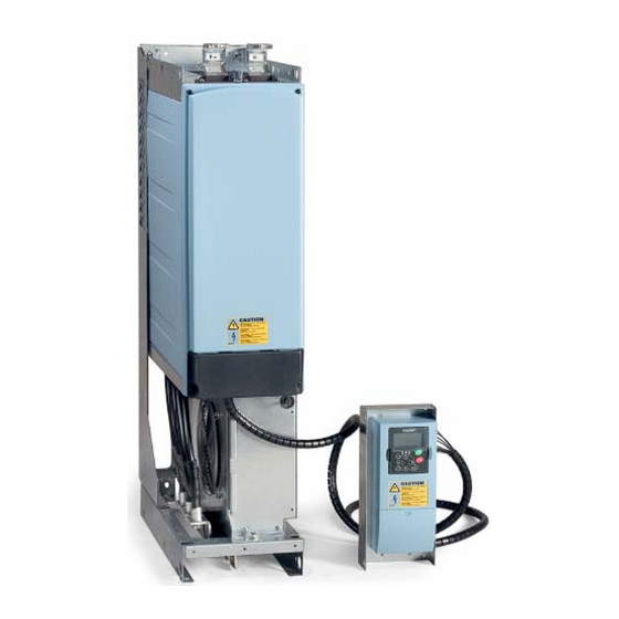
Introduction to Vacon Brake Chopper Unit
Operation Principle of BCU
Explains how the BCU slows down motors by dissipating energy in a brake resistor when dynamic braking is required.
Quick Start Instructions
Provides a step-by-step guide for commissioning BCU applications, emphasizing safety and parameter setup.
Brake Chopper Application Parameter Lists
Monitoring values (Control keypad: menu M1)
Lists actual parameter values, signals, statuses, and measurements that cannot be edited.
Basic parameters (Control keypad: Menu G2 → G2.1)
Details essential parameters for brake chopper operation level and manual identification of brake resistor connection.
Input signals (Control keypad: Menu G2 → G2.2)
Describes configuration for digital and analog inputs, including fault reset, external fault, run enable, and PT100 sensor selection.
Output signals (Control keypad: Menu G2 → G2.3)
Covers configuration of digital and analog outputs for controlling signals and relay outputs.
BCU In parallel (Control keypad: Menu G2 → G2.4)
Explains the 'Drooping' parameter for increasing braking current and its effect on DC link voltage in parallel BCU setups.
Fieldbus parameters (Control keypad: Menu G2 → G2.5)
Details parameters for selecting and configuring fieldbus data for monitoring and controlling the BCU.
Protections (Menu G2 → G2.6)
Outlines protection parameters related to PT100 sensors, thermistors, and external faults, defining responses to overtemperature or faults.
Keypad control (Control keypad: Menu M3)
Describes the parameter for changing the active control place between I/O terminal and fieldbus.
System menu (Control keypad: Menu M6)
Refers to parameters and functions for general converter use, application, language, and customization.
Expander boards (Control keypad: Menu M7)
Explains the menu for viewing expander and option boards attached to the control board.
Description of Parameters
Basic parameters
Details Brake Chopper Level and ID Run parameters for setting DC link voltage and identifying brake resistors.
Input signals
Explains digital and analog input parameters, including fault reset, external fault, run enable, and PT100 sensor configuration.
Output signals
Describes digital and analog output signals, including their selection, offset, filtering, and value ranges.
BCU In Parallel
Explains the 'Drooping' parameter for parallel BCU operation, affecting DC link voltage with braking current.
Fieldbus parameters
Covers parameters for selecting and configuring fieldbus data for monitoring and controlling the BCU.
Protections
Details parameters for PT100 inputs, alarm/fault limits, thermistor, and external fault responses.
Keypad control
Describes the parameter for selecting the active control place between I/O terminal and fieldbus.
Need help?
Do you have a question about the OPT-B8 and is the answer not in the manual?
Questions and answers