Bosch VIP X1 Installation And Operating Manual
Operation manual
Hide thumbs
Also See for VIP X1:
- Installation and operating manual (116 pages) ,
- Installation and user manual (104 pages) ,
- Quick installation manual (12 pages)
Table of Contents
Advertisement
Quick Links
Advertisement
Table of Contents

Related Manuals for Bosch VIP X1


Summary of Contents for Bosch VIP X1
- Page 1 VIP X1...
- Page 2 At the time of printing, the description was complete and correct. As the result of product improvements, the contents of this manual may change without notice. Bosch Security Systems assumes no liability for damage, either direct or indirect, arising from mistakes, incompleteness or discrepancies between this manual and the product described.
-
Page 3: Table Of Contents
MPEG-4 encoder ........41 Bosch Security Systems | 2006-12 | V2.5... - Page 4 Transfer and disposal....... . 122 Contents Bosch Security Systems | 2006-12 | V2.5...
- Page 5 Specifications ........135 Chapter 9 Index Bosch Security Systems | 2006-12 | V2.5 Contents...
- Page 6 EN | 6 Installation and Operating Manual | VIP X1 Contents Bosch Security Systems | 2006-12 | V2.5...
-
Page 7: Chapter 1 Preface
It is associated with immediate, direct hazards. Note This symbol refers to features and indicates tips and information for easier, more convenient use of the unit. Bosch Security Systems | 2006-12 | V2.5 Preface... -
Page 8: Intended Use
For exact identification, the model name and serial number are inscribed on the bottom of the housing. Please make a note of this information before installation if necessary so as to have it to hand in case of questions or when ordering spare parts. Preface Bosch Security Systems | 2006-12 | V2.5... -
Page 9: Chapter 2 Safety Information
– if foreign bodies have penetrated the unit, – after long storage under adverse conditions, or – after exposure to extreme stress in transit. In such cases, have the unit checked by Bosch Security Systems. Bosch Security Systems | 2006-12 | V2.5 Safety information... -
Page 10: Installation And Operation
Never open the housing of the power supply unit. The power supply unit does not contain any user-serviceable parts. Ensure that all maintenance or repair work is carried out only by qualified per- sonnel (electrical engineers or network technology specialists). Safety information Bosch Security Systems | 2006-12 | V2.5... -
Page 11: Chapter 3 Product Description
– Adobe Acrobat Reader Note Check that the delivery is complete and in perfect condition. Have your unit checked by Bosch Security Systems if you detect any damage. System requirements for setup Computer with Windows 2000/XP operating system, access to a network and Microsoft Internet Explorer (version 6.0 or higher) -
Page 12: Configuration Requirements
Computer with Windows 2000/XP operating system, access to a network and Microsoft Internet Explorer (version 6.0 or higher) Computer with Windows 2000/XP operating system, access to a network and receiver software, for example VIDOS or Bosch Video Management System MPEG-4 compatible hardware decoder from Bosch Security Systems... -
Page 13: Overview Of Functions
This feature creates two data streams that can serve different purposes, for example one for local recording and one optimized for transmission over the LAN. Bosch Security Systems | 2006-12 | V2.5 Product description... - Page 14 LIVEPAGE as well as on the RECORDINGS page. Video sequences can be stored by means of a mouse click and can be redis- played using the Player supplied as part of the scope of delivery. Product description Bosch Security Systems | 2006-12 | V2.5...
- Page 15 PoE power supply according to IEEE standard 802.11af (variant) The audio version also offers: Transmission and receipt of audio signals Bidirectional audio (mono) for line or microphone/speaker links Audio encoding to international standard G.711 Bosch Security Systems | 2006-12 | V2.5 Product description...
-
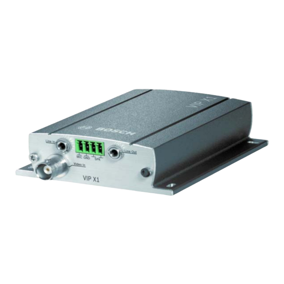
Page 16: Connections On The Front Panel
3 Audio line output Line Out (audio version only) 3.5 mm stereo jack socket for connecting an audio line output signal 4 Video input Video In BNC socket for connecting a video source Product description Bosch Security Systems | 2006-12 | V2.5... -
Page 17: Connections On The Rear Panel
11 RJ45 socket ETH for connecting to an Ethernet LAN (local network), 10/100 MBit Base-T For more information about the LEDs see page 126. For information about the terminal block connections see page 127. Bosch Security Systems | 2006-12 | V2.5 Product description... - Page 18 EN | 18 Installation and Operating Manual | VIP X1 Product description Bosch Security Systems | 2006-12 | V2.5...
-
Page 19: Chapter 4 Installation
Position and run all cables so that they are protected from damage, and pro- vide adequate cable strain relief where needed. Avoid impacts, blows and severe vibrations as these can irreparably damage the unit. Bosch Security Systems | 2006-12 | V2.5 Installation... -
Page 20: Connections
Impedance 2 kOhm typ., 2.8 V max. input voltage, –20 dB in, supply 2.3 V typ. SPK (speaker): Impedance 4 Ohm min., 6 V max. output voltage, power output RMS 1 W Installation Bosch Security Systems | 2006-12 | V2.5... - Page 21 Please take note of the appropriate documentation when installing and op- erating the unit to be controlled. The documentation contains important safety instructions and information about permitted uses. Note A video connection is necessary to transmit transparent data. Bosch Security Systems | 2006-12 | V2.5 Installation...
- Page 22 The maximum rating of the relay contact is 30 V and 2 A. – Connect the lines to the appropriate terminals on the orange terminal block (R) and check that the connection is secure. Installation Bosch Security Systems | 2006-12 | V2.5...
-
Page 23: Usb Interface
All other data on the drive is deleted as soon as the VIP X1 is switched on. – Connect the external drive to the USB port of the VIP X1 using a USB cable. Bosch Security Systems | 2006-12 | V2.5 Installation... -
Page 24: Power On/Power Off
"operating status" LED stops flashing red during start-up and lights up green. Provided the network connection has been correctly made, the green L LED also lights up. The flashing orange T LED indicates data traffic on the network. Installation Bosch Security Systems | 2006-12 | V2.5... -
Page 25: Setup Using The Configuration Manager
You can start the Configuration Manager immediately after installation. – Double click the icon on the desktop or start the program via the Start menu. After the program has started, the network is immediately searched for com- patible video servers. Bosch Security Systems | 2006-12 | V2.5 Installation... - Page 26 Reset command from the context menu. Additional parameters You can check and set additional parameters with the assistance of the Config- uration Manager. You can find detailed information on this in the documentation for this program. Installation Bosch Security Systems | 2006-12 | V2.5...
-
Page 27: Chapter 5 Configuration Using A Web Browser
If necessary, you can install the required software and controls from the product CD supplied (see Components supplied, page 11). Bosch Security Systems | 2006-12 | V2.5 Configuration using a Web browser... - Page 28 – Enter the IP address of the VIP X1 as the URL. The connection is established and after a short time you will see the LIVEPAGE with the video image. Configuration using a Web browser Bosch Security Systems | 2006-12 | V2.5...
- Page 29 If you do not connect, the device may have reached its maximum number of con- nections. Depending on the device and network configuration, up to 25 Web browser, or up to 50 VIDOS or Bosch Video Management System connections to each VIP X1 are supported.
-
Page 30: Configuration Menu
All settings are backed up in the VIP X1 memory so they are not lost even if the power fails. Start configuration – Click the SETTINGS link in the upper section of the window. The Web browser opens a new page with the configuration menu. Configuration using a Web browser Bosch Security Systems | 2006-12 | V2.5... - Page 31 Caution Save each change with the associated Set button. Clicking the Set button saves the settings only in the current field. Changes in any other fields are ignored. Bosch Security Systems | 2006-12 | V2.5 Configuration using a Web browser...
-
Page 32: Unit Identification
You can give the VIP X1 a name to make it easier to identify. The name makes the task of administering multiple units in larger video monitoring systems eas- ier, for example using the VIDOS or Bosch Video Management System pro- grams. - Page 33 You should therefore click the Set button immediately after entering and confirming a password, even if you also wish to subsequently assign a password to another user name. Bosch Security Systems | 2006-12 | V2.5 Configuration using a Web browser...
-
Page 34: Language
- it is added automatically. – Enter the current clock time or click the Synchr. PC button to apply the sys- tem time from your computer to the VIP X1. Configuration using a Web browser Bosch Security Systems | 2006-12 | V2.5... -
Page 35: Time Server
– Clicking the Delete button will remove the entry from the table. – Choose other values from the list boxes under the table, to change the selected entry. Changes are immediate. Bosch Security Systems | 2006-12 | V2.5 Configuration using a Web browser... -
Page 36: Camera Name
(see page 37). The camera name makes the task of administering cameras in larger video monitoring systems easier, for example using the VIDOS or Bosch Video Management System programs. Camera 1: Enter a unique, unambiguous name for the camera in this field. -
Page 37: Display Stamping
– If you select the Custom option, additional fields are displayed where you can specify the exact position (Position (XY):). – In the Position (XY): fields enter the values for the desired position. Bosch Security Systems | 2006-12 | V2.5 Configuration using a Web browser... - Page 38 Choose On if you wish the transmitted video images to be "watermarked". After activation, all images are marked with a small green rectangle. A red rect- angle indicates that the sequence (live or saved) has been manipulated. Configuration using a Web browser Bosch Security Systems | 2006-12 | V2.5...
-
Page 39: Picture Settings
Brightness (0...255): You can use this function to adapt the brightness of the video image to your working environment. Bosch Security Systems | 2006-12 | V2.5 Configuration using a Web browser... - Page 40 Check your settings controlling the video window next to the slide controls. Also watch the indicator for the processor load displayed on top of the window on the left of the unit name (compare page 126). Configuration using a Web browser Bosch Security Systems | 2006-12 | V2.5...
-
Page 41: Mpeg-4 Encoder
Profile 4: DSL For DSL connections at 500 kBit/s, resolution 352 × 288/240 pixels Profile 5: ISDN (2B) For ISDN connections via two B channels, resolution 352 × 288/240 pixels Bosch Security Systems | 2006-12 | V2.5 Configuration using a Web browser... - Page 42 Check the box for the required data stream. Configuration using a Web browser Bosch Security Systems | 2006-12 | V2.5...
- Page 43 Profile name: You can enter a new name for the profile here. The name is then displayed in the list of available profiles in the Active profile: field. Bosch Security Systems | 2006-12 | V2.5 Configuration using a Web browser...
- Page 44 After clicking the Details >> button, further settings for image quality and com- munication parameters are displayed. These settings require familiarity with MPEG and video encoding standards. Incorrect settings could result in useless video images. Configuration using a Web browser Bosch Security Systems | 2006-12 | V2.5...
- Page 45 An entry of 2 indicates that only every second image is an I-frame, and 3 only every third image etc.; the frames in between are coded as P-frames. Bosch Security Systems | 2006-12 | V2.5 Configuration using a Web browser...
-
Page 46: Video Input
Note In some cases, selecting the VCR option can lead to an improvement in the video image even with a camera connected. Configuration using a Web browser Bosch Security Systems | 2006-12 | V2.5... -
Page 47: Audio Settings (Audio Version Only)
Selection Click one of the option boxes and then click Set to display the level of the respec- tive audio input for orientation and to set the gain. Bosch Security Systems | 2006-12 | V2.5 Configuration using a Web browser... -
Page 48: Jpeg Posting
When setting this parameter, ensure that the unit's date and time are always correctly set. Example: the file snap011005_114530.jpg was stored on Octo- ber 1, 2005 at 12.45 p.m. and 30 seconds. Configuration using a Web browser Bosch Security Systems | 2006-12 | V2.5... - Page 49 Enter the password that gives you access to the FTP server. Path on FTP server: Enter the exact path on which you wish to post the images on the FTP server. Bosch Security Systems | 2006-12 | V2.5 Configuration using a Web browser...
-
Page 50: Storage Medium
The VRM is an external program for con- figuring recording tasks for video servers. For further information, please contact your local customer service at Bosch Security Systems. Type: Select the desired storage medium to subsequently configure the recording parameters. - Page 51 – In this window, click Delete to delete all entries. The entries will be deleted immediately; you cannot undo this process. – Click the Close button to close the window. Bosch Security Systems | 2006-12 | V2.5 Configuration using a Web browser...
-
Page 52: Iscsi Settings
– Enter the IP address of the required iSCSI server here. – Click the Read button. The connection to the IP address will be established. The iSCSI LUN map field contains the corresponding logical drives. Configuration using a Web browser Bosch Security Systems | 2006-12 | V2.5... - Page 53 Target password: If the drive is password protected, enter the password. Note You may not enter a new password. This is only possible by configuring the iSCSI storage device. Bosch Security Systems | 2006-12 | V2.5 Configuration using a Web browser...
- Page 54 – Double-click a drive that is already being used in the LUN map. You will see a warning message. – Confirm the decoupling of the current user. The drive is released and can now be connected to the VIP X1. Configuration using a Web browser Bosch Security Systems | 2006-12 | V2.5...
- Page 55 – In this window, click Delete to delete all entries. The entries will be deleted immediately; you cannot undo this process. – Click the Close button to close the window. Bosch Security Systems | 2006-12 | V2.5 Configuration using a Web browser...
-
Page 56: Partitioning
Creating a new partition is performed using separate windows in which informa- tion is presented to you and you are led step by step through the necessary set- tings. The process must be completed once. Configuration using a Web browser Bosch Security Systems | 2006-12 | V2.5... - Page 57 After you have made all necessary settings, you must transfer the settings to the unit and save them. To do this, you need to quit the help in the last window using the Finish button. Bosch Security Systems | 2006-12 | V2.5 Configuration using a Web browser...
- Page 58 Finish. – Switch to the last window if necessary. – Click Finish to complete the configuration. All settings are now transferred to the unit and subsequently become effective. Configuration using a Web browser Bosch Security Systems | 2006-12 | V2.5...
- Page 59 – In the list, click the partition to highlight it. – Click the Partition status button. A window will open showing information on the partition. – Click OK to close the window. Bosch Security Systems | 2006-12 | V2.5 Configuration using a Web browser...
- Page 60 – Click the Set button to save the modifications. – After closing the window, click the Set button in the main window to transfer the changes to the unit and to save them. Configuration using a Web browser Bosch Security Systems | 2006-12 | V2.5...
- Page 61 – Click the Calculate button. A window will open. – Select the appropriate setting for each parameter from the list boxes. Click the Set button to accept the calculated value. Bosch Security Systems | 2006-12 | V2.5 Configuration using a Web browser...
- Page 62 01, the partition name is deleted and the size is indicated as 0. – Click the Set button to transfer the changes to the unit and to save them. Configuration using a Web browser Bosch Security Systems | 2006-12 | V2.5...
-
Page 63: Recording Profiles
A dialog will appear, and you can select the target pro- file for the copied settings. – Click the Set button in each profile tab to save the settings in the device. Bosch Security Systems | 2006-12 | V2.5 Configuration using a Web browser... - Page 64 You can select the encoder profile to use for recording during the post-alarm time (compare page 42). The Standard profile option sets this to the same as the standard profile. Configuration using a Web browser Bosch Security Systems | 2006-12 | V2.5...
- Page 65 VCA (see page 73). The numbering of the check boxes for the alarm inputs corresponds to the label- ing of the alarm inputs on the VIP X1. Bosch Security Systems | 2006-12 | V2.5 Configuration using a Web browser...
-
Page 66: Recording Scheduler
– Use the right mouse button to deselect any of the intervals. – Click the Select all button to select all of the intervals to be assigned to the selected profile. Configuration using a Web browser Bosch Security Systems | 2006-12 | V2.5... - Page 67 You can change the names of the recording profiles. – Select a profile by clicking and then click Rename. – Enter the desired name and click Rename again. Bosch Security Systems | 2006-12 | V2.5 Configuration using a Web browser...
- Page 68 Recording status: The graphic indicates the recording activity of the VIP X1. You will see an ani- mated graphic while recording is taking place. Configuration using a Web browser Bosch Security Systems | 2006-12 | V2.5...
-
Page 69: Alarm Sources
LIVEPAGE if configured correctly (see Livepage configuration, page 94). Video loss alarm: Activate the checkbox if you want an interruption of the video signal to also trig- ger an alarm. Bosch Security Systems | 2006-12 | V2.5 Configuration using a Web browser... -
Page 70: Alarm Connections
The unit contacts the remote stations one after the other in the numbered sequence until a connection is made. Destination IP address: For each number enter the corresponding IP address for the desired remote sta- tion. Configuration using a Web browser Bosch Security Systems | 2006-12 | V2.5... - Page 71 If more than ten con- nections are necessary, for example when connections are initiated by a control- ling system, such as VIDOS or Bosch Video Management System, you can define a general password. The VIP X1 can make connections with this general password to all devices protected by that same password.
- Page 72 (see page 42). Audio: (audio version only) Select the option On if you wish to additionally transmit a standalone G.711 encoded audio stream with alarm connections. Configuration using a Web browser Bosch Security Systems | 2006-12 | V2.5...
-
Page 73: Vca
If you have selected MOTION+ analysis, for example, the sensor fields in which movement is registered are marked by rectangles. Bosch Security Systems | 2006-12 | V2.5 Configuration using a Web browser... - Page 74 Note Additional analysis algorithms with comprehensive functions such as IVMD are available from Bosch Security Systems. Motion detector (MOTION+ only) For the detector to function, the following conditions must be met: Analysis must be activated.
- Page 75 – Right-click any fields you wish to deactivate. – Click OK to save the configuration. – Click the close button (X) in the window title bar to close the window without saving the changes. Bosch Security Systems | 2006-12 | V2.5 Configuration using a Web browser...
- Page 76 Activate this function if tampering associated with covering the objective (for instance, by spraying paint on it) should trigger an alarm. The average brightness of the scene provides a basis for recognition. Configuration using a Web browser Bosch Security Systems | 2006-12 | V2.5...
- Page 77 – Check the box Reference check to activate on-going matching. The stored reference image is displayed in black and white below the current video image, and the selected areas are marked in red. Bosch Security Systems | 2006-12 | V2.5 Configuration using a Web browser...
- Page 78 – Right-click any fields you wish to deactivate. – Click OK to save the configuration. – Click the close button (X) in the window title bar to close the window without saving the changes. Configuration using a Web browser Bosch Security Systems | 2006-12 | V2.5...
-
Page 79: Alarm E-Mail
Standard (with JPEG): e-mail with attached JPEG image file. SMS: e-mail in SMS format to an e-mail-to-SMS gateway (for example to send an alarm by cellphone) without an image attachment. Bosch Security Systems | 2006-12 | V2.5 Configuration using a Web browser... - Page 80 This will make it easier to identify the origin of the e-mail. Send e-mail for testing: Test the e-mail function by clicking the Send now button. An alarm e-mail is immediately created and sent. Configuration using a Web browser Bosch Security Systems | 2006-12 | V2.5...
-
Page 81: Relay
For example, if you want an alarm-activated lamp to stay on after the alarm ends, select Bistable. If you wish an alarm-activated siren to sound for 10 sec- onds, for example, select 10 sec. Bosch Security Systems | 2006-12 | V2.5 Configuration using a Web browser... - Page 82 Trigger relay. The Livepage can also be configured to display the name under the relay icon. Trigger relay: Click the button to trigger the relay manually (for testing or to operate a door opener, for example). Configuration using a Web browser Bosch Security Systems | 2006-12 | V2.5...
-
Page 83: Com1
Camera ID: If necessary, enter the ID of the peripheral you wish to control (for example a dome camera or pan/tilt head). Bosch Security Systems | 2006-12 | V2.5 Configuration using a Web browser... -
Page 84: Baud Rate
Select the number of stop bits per character. Parity check: Select the type of parity check. Interface mode: Select the desired protocol for the serial interface. Half-duplex mode: Choose the setting appropriate for your application. Configuration using a Web browser Bosch Security Systems | 2006-12 | V2.5... -
Page 85: Network
Some changes, for example to the IP address, subnet mask or gateway address are transferred to the unit by clicking Set. However, they only take effect after the unit is restarted! Note the indicator Reboot after ’Set’ necessary! Bosch Security Systems | 2006-12 | V2.5 Configuration using a Web browser... - Page 86 Select a different HTTP browser port from the list if required. The default HTTP port is 80. If you want to limit connection to HTTPS you must deactivate the HTTP port. To do this activate the Off option. Configuration using a Web browser Bosch Security Systems | 2006-12 | V2.5...
- Page 87 (traps) to IP addresses. It supports SNMP MIB II in the unified code. If you wish to send SNMP traps, enter the IP addresses of one or two required target devices here. Bosch Security Systems | 2006-12 | V2.5 Configuration using a Web browser...
- Page 88 IP address after each restart. If not, the unit may no longer be accessible via its IP address, or controlling systems, such as VIDOS or Bosch Video Management System loose the allocations. Configuration using a Web browser...
-
Page 89: Multicasting
Multicast address video 1: Enter a valid multicast address for each stream to be operated in multicast mode (duplication of the data streams in the network). Bosch Security Systems | 2006-12 | V2.5 Configuration using a Web browser... - Page 90 You can enter a value to specify how long the multicast data packets are active on the network. This value must be greater than one if multicast is to be run via a router. Configuration using a Web browser Bosch Security Systems | 2006-12 | V2.5...
-
Page 91: Encryption
If you delete the key, unencrypted data is transmitted in the respective channel. Note Encrypting video data requires a lot of computing power. Bosch Security Systems | 2006-12 | V2.5 Configuration using a Web browser... - Page 92 You can activate an automatic key exchange between two devices (or a device and a software decoder) across an encrypted connection. If the checkbox is marked keys are exchanged automatically. Configuration using a Web browser Bosch Security Systems | 2006-12 | V2.5...
-
Page 93: Version Information
Note You can use the mouse to mark and copy the firmware and hardware ver- sion numbers, for example to send them via e-mail. Bosch Security Systems | 2006-12 | V2.5 Configuration using a Web browser... -
Page 94: Livepage Configuration
The image file is not stored in the VIP X1. – Check the box for the items that are to be displayed on the LIVEPAGE. The selected items are indicated by a check mark. Configuration using a Web browser Bosch Security Systems | 2006-12 | V2.5... - Page 95 Show relay output: The relay output is shown next to the video image as an icon, along with its assigned name. If the relay is switched, the icon changes color. Bosch Security Systems | 2006-12 | V2.5 Configuration using a Web browser...
- Page 96 You can then view, edit and print this file with any text editor or the standard Office software. File for event log: Enter the path to save the event log here. – If necessary, click Browse to find a suitable folder. Configuration using a Web browser Bosch Security Systems | 2006-12 | V2.5...
-
Page 97: Licenses
You can enter the activation key to release additional functions or software mod- ules. Note The activation key cannot be deactivated again and is not transferable to other units. Bosch Security Systems | 2006-12 | V2.5 Configuration using a Web browser... -
Page 98: Maintenance
The new firmware is unpacked and the Flash EPROM is reprogrammed. The time remaining is shown by the message going to reset Reconnecting in ... seconds. The unit restarts automatically once the upload has successfully completed. Configuration using a Web browser Bosch Security Systems | 2006-12 | V2.5... - Page 99 – Enter the complete path name of the file you wish to upload, or click Browse... to locate the file. – Click Upload to start the file transfer. Bosch Security Systems | 2006-12 | V2.5 Configuration using a Web browser...
- Page 100 – After successful upload of all files you must reboot the device. Enter the IP address of the VIP X1 followed by /reset (for example 192.168.0.30/ reset) in the address bar of your Web browser. The new SSL certificate is valid. Configuration using a Web browser Bosch Security Systems | 2006-12 | V2.5...
-
Page 101: Function Test
Does the VIP X1 transmit all the data required? Does the VIP X1 respond to alarm events as required? Do the recordings occur as intended? Is it possible to control peripherals if necessary? Bosch Security Systems | 2006-12 | V2.5 Configuration using a Web browser... - Page 102 EN | 102 Installation and Operating Manual | VIP X1 Configuration using a Web browser Bosch Security Systems | 2006-12 | V2.5...
-
Page 103: Chapter 6 Operation
– Insert the CD in the CD-ROM drive of the computer. If the CD does not start automatically, open the root directory of the CD in Windows Explorer and double click MPEGAx.exe. – Follow the on-screen instructions. Bosch Security Systems | 2006-12 | V2.5 Operation... - Page 104 – Start the Web browser. – Enter the IP address of the VIP X1 as the URL. The connection is established and after a short time you will see the LIVEPAGE with the video image. Operation Bosch Security Systems | 2006-12 | V2.5...
-
Page 105: The Livepage
If you do not connect, the device may have reached its maximum number of con- nections. Depending on the device and network configuration, up to 25 Web browser, or up to 50 VIDOS or Bosch Video Management System connections to each VIP X1 are supported. - Page 106 – To activate this, click the icon for the relay next to the video image. The icon will be red when the relay is activated. Operation Bosch Security Systems | 2006-12 | V2.5...
- Page 107 Note When the connection maintaining voice contact with the VIP X1 is broken, the next user to make a connection to the VIP X1 can send audio data to the VIP X1. Bosch Security Systems | 2006-12 | V2.5 Operation...
-
Page 108: Saving Snapshots
– Click the icon for recording video sequences again to stop recording. Note You can play back saved video sequences using the Player from Bosch Security Systems which can be installed from the product CD sup- plied (see page 115). Image resolution Sequences are saved at the resolution that has been preset in the configuration for the encoder (see page 44). -
Page 109: Running Recording Program
The hard drive icon below the camera images on the LIVEPAGE changes during an automatic recording. The icon lights up green and displays a moving graphic to indicate a running recording. If no recording is taking place, a gray icon is displayed. Bosch Security Systems | 2006-12 | V2.5 Operation... -
Page 110: The Recordings Page
The RECORDINGS link is only visible if a storage medium has been selected (see page 50). – Click in the navigation bar in the upper section of the window on the link RECORDINGS. The playback page appears. Operation Bosch Security Systems | 2006-12 | V2.5... - Page 111 The display can span a range from two months to a few seconds. – You can select a different sequence for playback by clicking on the corre- sponding gray marking. Bosch Security Systems | 2006-12 | V2.5 Operation...
- Page 112 You can continuously select playback speed by means of the speed regulator: Red bars within the gray sequence fields indicate the points in time where alarms were triggered. Drag the green arrow to navigate to these points quickly. Operation Bosch Security Systems | 2006-12 | V2.5...
- Page 113 – Right-click a bookmark to delete it. Note Bookmarks are only valid while you are in the RECORDINGS page; they are not saved with the sequences. As soon as you leave the page all book- marks are deleted. Bosch Security Systems | 2006-12 | V2.5 Operation...
-
Page 114: Backup
The single images are immediately displayed in the Screenshots area after clicking. The storage location for the sequences and single images can be specified in the configuration of the VIP X1 (see page 97). Operation Bosch Security Systems | 2006-12 | V2.5... -
Page 115: Installing Player
EN | 115 Installing Player You can play back saved video sequences using the Player from Bosch Security Systems which can be found on the product CD supplied (see Components supplied, page 11). Note Suitable MPEG ActiveX software must be installed on the computer in or- der to play back saved video sequences using the Player. -
Page 116: Replaying Usb Hard Drive Recordings On Pc
The software of a virtual video server is started, and you can access the play- back page on this unit by entering the IP address of your own computer in Internet Explorer (for example 192.168.0.1). Operation Bosch Security Systems | 2006-12 | V2.5... - Page 117 VIP X1 (see page 111). Note You must restart the virtual video server software if you restart the com- puter or if you change the USB drive, by double-clicking on the video- jet.exe file again. Bosch Security Systems | 2006-12 | V2.5 Operation...
-
Page 118: Hardware Connections Between Video Servers
Internet Explorer. Note Connecting with a Web browser is described in the manual of the relevant unit that is to be used as the receiver, for example VIP XD. Operation Bosch Security Systems | 2006-12 | V2.5... - Page 119 – Start the terminal program (see page 129) and enter the command 4 in the main menu to switch to the Rcp+ menu. – In the Rcp+ menu, enter the command 5 to deactivate the automatic connec- tion. Bosch Security Systems | 2006-12 | V2.5 Operation...
-
Page 120: Operation With Decoder Software
Bosch Video Management System is a unique enterprise IP video security solu- tion that provides seamless management of digital video, audio and data across any IP network. It is designed to work with Bosch CCTV products as part of a total video security management system. Now you can integrate your existing components into one easy-to-manage system, or use Bosch’s full-line capabili-... -
Page 121: Chapter 7 Maintenance And Upgrades
The IP address can be changed as described in the chapter "Instal- lation" (see page 25). – If necessary, back up the current configuration using the Download button on the Maintenance configuration page (see page 98). Bosch Security Systems | 2006-12 | V2.5 Maintenance and upgrades... -
Page 122: Repairs
The VIP X1 should only be passed on together with this installation and operat- ing manual. Your Bosch product is designed and manufactured with high quality materials and components which can be recycled and reused. This symbol means that electrical and electronic equipment, at their end-of-life, should be disposed of separately from your household waste. -
Page 123: Troubleshooting
Troubleshooting If you are unable to resolve a malfunction, please contact your supplier or sys- tems integrator, or go directly to Bosch Security Systems Customer Service. The version numbers of the internal processors can be viewed on a special page. Make a note of this information before contacting Customer Service. -
Page 124: General Malfunctions
Check the audio parameters on the Audio settings and Livepage configuration configuration pages. The audio voice connection Wait until the connection is free is already in use by another and then call the sender again. receiver. Appendix Bosch Security Systems | 2006-12 | V2.5... - Page 125 LUN mapping is not Some iSCSI systems don’t Delete the initiator extension on the possible. support initiator extensions. iSCSI settings configuration page. Bosch Security Systems | 2006-12 | V2.5 Appendix...
-
Page 126: Leds
Move the mouse cursor over the icon to display numerical values for the processor. This information can help with problem solving or when fine tuning the device. Appendix Bosch Security Systems | 2006-12 | V2.5... -
Page 127: Serial Interface
The standard used depends on the current configuration (see page 83). Connection is via the terminal connector. Terminal block The terminal block has several contacts for: 4 alarm inputs 1 relay output Serial data transmission Bosch Security Systems | 2006-12 | V2.5 Appendix... -
Page 128: Pin Assignment
TxD+ (transmit data plus) 12 V (power supply) 12 V (power supply) – GND (ground) GND (ground) To operate the alarm inputs, connect each alarm input to a ground contact (GND) via a trigger contact. Appendix Bosch Security Systems | 2006-12 | V2.5... -
Page 129: Communication With Terminal Program
Before the terminal program can communicate with the VIP X1, the transmission parameters must be matched. Make the following settings for the terminal pro- gram: 19,200 bit/s 8 data bits No parity check 1 stop bit No protocol Bosch Security Systems | 2006-12 | V2.5 Appendix... - Page 130 The following default address is preset at the factory: 192.168.0.1 – Start a terminal program such as HyperTerminal. – Enter the user name service. The terminal program displays the main menu. – Enter the command 1 to open the IP menu. Appendix Bosch Security Systems | 2006-12 | V2.5...
- Page 131 Additional parameters You can use the terminal program to check other basic parameters and modify them where necessary. Use the on-screen commands in the various submenus to do this. Bosch Security Systems | 2006-12 | V2.5 Appendix...
-
Page 132: Glossary
Transfer Control Protocol (TCP): TCP/IP See Internet Protocol IP address A 4-byte number uniquely defining each unit on the Internet. It is usually written in dotted decimal notation, for example "209.130.2.193" Appendix Bosch Security Systems | 2006-12 | V2.5... - Page 133 SNIA Storage Networking Industry Association; association of compa- nies for defining the iSCSI standard SNMP Simple Network Management Protocol; a protocol for network management, for managing and monitoring network compo- nents Bosch Security Systems | 2006-12 | V2.5 Appendix...
- Page 134 Time-To-Live; life cycle of a data packet in station transfers User Datagram Protocol Uniform Resource Locator Unshielded Twisted Pair See Wide area network Wide area network A long distance link used to extend or connect remotely located local area networks Appendix Bosch Security Systems | 2006-12 | V2.5...
-
Page 135: Specifications
20 ... 80%, non-precipitating Regulatory approvals CE: IEC 60950; UL 1950; AS/NZS 3548; EN 55103-1, -2; EN 55130-4; EN 55022; EN 55024; EN 61000-3-2; EN 61000-3-3; FCC 47 CFR Chapter 1 Part 15 Bosch Security Systems | 2006-12 | V2.5 Appendix... - Page 136 RTP, Telnet, TCP, UDP, IP, HTTP, HTTPS, DHCP, IGMP V2, IGMP V3, ICMP, ARP, SNMP V2, 802.1x Audio version only: Audio coding protocol G.711 Audio sampling rate 8 kHz Audio data rate 80 kBit/s Appendix Bosch Security Systems | 2006-12 | V2.5...
- Page 137 Date 34 Date format 34 Camera 83 Daylight saving time 35 Camera name 36 Default settings 63 Camera selection 105 Defaults 44 Cameras 20 Defaults recording profiles 63 Changes 31 Deleting partitions 62 Bosch Security Systems | 2006-12 | V2.5 Index...
- Page 138 Function test 101 Linear mode 61 Live video images 27 Gateway 86 Livepage 94 General password 71 Loudspeaker 21 Low Voltage Directive 8 Low-pass filter 40 Half-duplex mode 84 Hardware version 93 Index Bosch Security Systems | 2006-12 | V2.5...
- Page 139 Profile settings 43 Navigation 31 Profiles 41 Network 22 Protocol 84 Network check 121 Protocols 136 Network connection 24 Number of connections 29 RADIUS 88 Rear panel 17 Operation 9 Receiver 13 Bosch Security Systems | 2006-12 | V2.5 Index...
- Page 140 Signal source 22 Time zone 35 Size alarm track 61 TLS 87 SMS 79 Transmission parameters 129 Snapshots 14 Transmission protocol 86 SNMP 87 Transmission rate 84 SNTP server 36 Transmission standards 21 Index Bosch Security Systems | 2006-12 | V2.5...
- Page 141 User name 33 VCA metadata 73 VCR 46 Version 93 Video content analysis 73 Video input 16 Video loss alarm 69 Video recorder 46 Video sensor 73 Video signal interruption 69 Watermarking 38 Bosch Security Systems | 2006-12 | V2.5 Index...
- Page 142 EN | 142 Installation and Operating Manual | VIP X1 Index Bosch Security Systems | 2006-12 | V2.5...
- Page 144 Bosch Sicherheitssysteme GmbH Bosch Security Systems B.V. Robert-Koch-Straße 100 P.O. Box 80002 85521 Ottobrunn 5600 JB Eindhoven Germany The Netherlands www.bosch-sicherheitssysteme.de www.boschsecuritysystems.com © 2006 Bosch Sicherheitssysteme GmbH Subject to change. 2501B/1206/en/4...