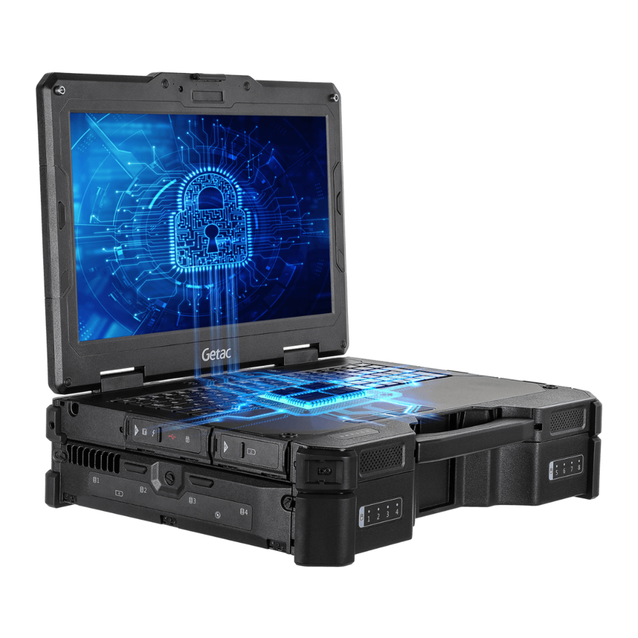
Getac X600 Series Manual
- User manual (52 pages) ,
- Quick start manual (6 pages) ,
- User manual (24 pages)
Advertisement
Overview
The Expansion Unit provides the functions as listed below.

| Ref | Component | Description | |
 | Battery pack (  ) ) | Provides additional battery power to your computer. | |
 | Optical disc drive | Accepts an optical disc. | |
 | PCI or PCIe slot | Inside is the PCI or PCIe expansion slot depending on your model. Each slot supports 25 W power. | |
 PCI Revision 2.0 |  PCI Express 3.0 (PCIe Gen 3) Slot 1: PCI Express x8 lanes Slot 2: PCI Express x1 lane | ||
| You can install up to two add-on cards. For information on installing an add-card card, see Section "Installing the Unit". | |||
 | Battery pack (  ) ) | Provides additional battery power to your computer. | |
 | Express Card slot | Accepts an ExpressCard/34 or ExpressCard/54 for additional functions. | |
 | PC card slot | Accepts a PC card for additional functions. | |
 | Serial connector (COM3) | Connects a serial device. | |
Scenario A
If the Expansion Unit kit was purchased separately for a standard X600 model, you have to install the Expansion Unit by yourself.
NOTE: You must use the 230 W AC adapter with the computer that has the Expansion Unit installed.
Scenario B
If your computer model is X600 Pro-PCI, the lower half of the computer is the Expansion Unit.
Attaching the Unit
NOTE: Skip this section if your computer model is X600 Pro-PCI.
If you have purchased the Expansion Unit separately for a standard X600 model, follow the instructions in this section to attach the Expansion Unit to the bottom of the computer.
The process includes five major parts:
- Make X600 ready for the installation.
- Disassemble the Expansion Unit.
- Attach the Expansion Unit cabinet to the computer.
- Reassemble the Expansion Unit.
- Install the battery packs and the optical disc drive.
- Make X600 ready for the installation.
- Remove the two battery packs from X600.
To remove a battery pack, pull its ribbon strip toward the right to unlock and then pull the battery pack out of the compartment. - Remove the DDR cover from the bottom of X600 by unfastening 15 screws (as indicated by the arrows below).
NOTE: The DDR cover will not be needed as long as the Expansion Unit is installed.

- Detach the docking connector piece by unfastening three screws (as indicated by the arrows below). Note that there are cable connectors to be unplugged.
Detach the antenna pass-through piece if your model has it.
NOTE: The two pieces will not be needed for the Expansion Unit, meaning the functions are not available when the Expansion Unit is installed.

- Unfasten 11 screws (as indicated by the arrows below). One of them is from the DDR holder while the others are from the bottom cover.

- Remove the two battery packs from X600.
- Disassemble the Expansion Unit.
- Remove the four corner bumpers from the Expansion Unit by unfastening four screws (as indicated by the arrows below).

- Insert your fingers at the two dented corners (as indicated by the dotted circles below) to pry up the bottom cover and then detach the cover from the cabinet.

- There is a metal plate as the middle layer inside the cabinet. Detach this plate from the cabinet.

- Detach the PCI/PCIe printed circuit board from the cabinet by unfastening two screws (as indicated by the arrows below).

- Remove the four corner bumpers from the Expansion Unit by unfastening four screws (as indicated by the arrows below).
- Attach the Expansion Unit cabinet to the computer.
- Align and attach the empty cabinet to the bottom of X600.

- Secure the cabinet by fastening 22 screws as indicated below. Find the matching screws from the Expansion Unit package.

- Align and attach the empty cabinet to the bottom of X600.


| Ref | Screw Type | Quantity |
| A | M2.6L6 | 12 |
| B | M3L12 | 4 |
| C | M2.6L14 | 6 |
- Bring the PCI/PCIe printed circuit board near the cabinet so that you can connect the male connector of the 10-pin power cable to the motherboard. (See the dotted circle below for the connector position.)

- Align and fit the PCI/PCIe printed circuit board back into place. Note that the 10-pin power cable should go through the notch at the edge of the board.
![]()
- Secure the board by fastening 19 screws as indicated below. Find the matching screws from the Expansion Unit package.


| Ref | Screw Type | Quantity |
| A | M2.0L4 | 15 |
| B | M2.6L20 | 4 |
- Connect the two 3-pin fan power cables to the PCI/PCIe printed circuit board. (See the dotted circles below for the connector positions.)
- Now the Expansion Unit is ready for add-on cards to be installed. (See Section "Installing the Unit" for add-on card installation instructions.)
- Reassemble the Expansion Unit.
- Follow steps 1 to 7 in Section "Reassembling the Unit" to reassemble the Expansion Unit.
- Install the battery packs and the optical disc drive.
- The Expansion Unit has two battery compartments for two battery packs; each is installed in the same way.
Locate the battery compartment and open its cover. Noting the orientation, insert the battery pack all the way into the compartment. Using the ribbon strip, slide the locking latch toward the locked position (![]() ). The latch should click into place.
). The latch should click into place.
![]()
- Locate the optical disc drive compartment and open its cover. Noting the orientation, insert the drive all the way into the compartment. Pull the ribbon strip downward to lock the dive in place.

- The Expansion Unit has two battery compartments for two battery packs; each is installed in the same way.
 ). The latch should click into place.

Accessing the Expansion Slots
NOTE: After removing screws, be sure to keep the screws and remember where they were removed. All screws are required for later use.
The expansion slots are inside the Expansion Unit. To access the expansion slots, you have to partially disassemble the Expansion Unit.
- Remove the four battery packs and the optical disc drive.
To remove a battery pack, pull its ribbon strip toward the right to unlock and then pull the battery pack out of the compartment.
To remove the optical disc drive, pull its ribbon strip upward to unlock and then pull the drive out of the compartment.

- Remove the four corner bumpers by unfastening three screws from each bumper.

- Remove the two hex standoffs from both sides of the RS-232 connector.

- Unfasten 34 bottom screws (as indicated by the arrows below). Note that two of the screws are shorter ones (as indicated by the dotted circles).

- Slightly lift up the bottom cover from one side by inserting your fingers at the two dented corners (as indicated by the fingers below). Be careful not to pull the fan cable underneath the cover.

- Rotate open the bottom cover, disconnect the fan cable connector from the printed circuit board on the metal plate, and then remove the bottom cover.

- Disconnect the power cable connector from the printed circuit board on the metal plate.

- Remove the metal plate by unfastening 16 screws (as indicated by the arrows below). Note that the two screws from the printed circuit board are longer ones (as indicated by the dotted circles).

- Now you can access the expansion slots. See Section "Installing the Unit" for add-on card installation instructions


Installing the Unit
NOTE:
- Before using an add-on card, it is suggested that you send the card to Getac for compatibility test.
- The PCI slots do not support "ATA 66" add-on cards.

- If your computer has the Expansion Unit already attached, you have to partially disassemble the Expansion Unit in order to access the expansion slots. (See Section "Accessing the Expansion Slots" for disassembly instructions.)
If the Expansion Unit was purchased separately and has not been attached to the computer yet, see Section "Attaching the Unit" for information. - Depending on which slot you want to use, remove its bracket by unfastening two screws.

- Align and attach the bracket to the add-on card's bracket and tighten one screw.

- Align the add-on card's connector with the slot and firmly press the connector into the slot. Secure the bracket with two screws (the screws from step 2).


To prevent damaging the golden fingers of an add-on card, do not use excessive force when inserting the gold fingers into the slot.
- Four rubber pads of two different sizes are supplied with the Expansion Unit or your computer. As add-on cards come in different sizes, you can use a rubber pad to help holding a card that might need extra support.
Detach the release liner from the adhesive tape on the pad, fit the notch of the pad to the edge of the add-on card where appropriate, and stick the pad to the printed circuit board. (See the figure above for reference.)
Reassembling the Unit
This section describes how to reassemble the Expansion Unit after installing an add-on card.
Depending on your situation, the screws needed for reassembling are either the ones previously removed or the screws supplied in the Expansion Unit package you purchased.
- Bring the metal plate near the cabinet and connect the power cable. (See the dotted circle below for the connector position.)

- Align the metal plate with the guide pins in the cabinet and fit the metal plate back into place. Make sure the power cable mentioned in the previous step is properly routed.
- Secure the metal plate with 16 screws as mentioned below. (See the figure for step 8 in Section "Accessing the Expansion Slots" for the screw positions.)

| Screw Type | Quantity |
| M2.0L4 | 14 |
| M2.6L20 | 2 |
- Bring the bottom cover near the cabinet so that you can connect the fan cable to the printed circuit board. (See the figure for step 6 in Section "Accessing the Expansion Slots" for the connector position.)
- Align and fit the bottom cover back into place. Secure the bottom cover with 34 screws as mentioned below. (See the figure for step 4 in Section "Accessing the Expansion Slots" for the screw positions.)
| Screw Type | Quantity |
| M2.6L6 | 32 |
| M2.6L4 | 2 |
- Tighten the two hex standoffs to both sides of the RS-232 connector. (See the figure for step 3 in Section "Accessing the Expansion Slots" for the standoff positions.)
- Fit the four corner bumpers into place. Note the position of each bumper and secure each with three screws. (See the figure for step 2 in Section "Accessing the Expansion Slots" for the screw positions.)
| Screw Type | Quantity |
| M2.6L6 | 12 |
- Replace the optical disc drive and the battery packs.
Documents / ResourcesDownload manual
Here you can download full pdf version of manual, it may contain additional safety instructions, warranty information, FCC rules, etc.
Advertisement


Need help?
Do you have a question about the X600 Series and is the answer not in the manual?
Questions and answers