Advertisement
Parts List
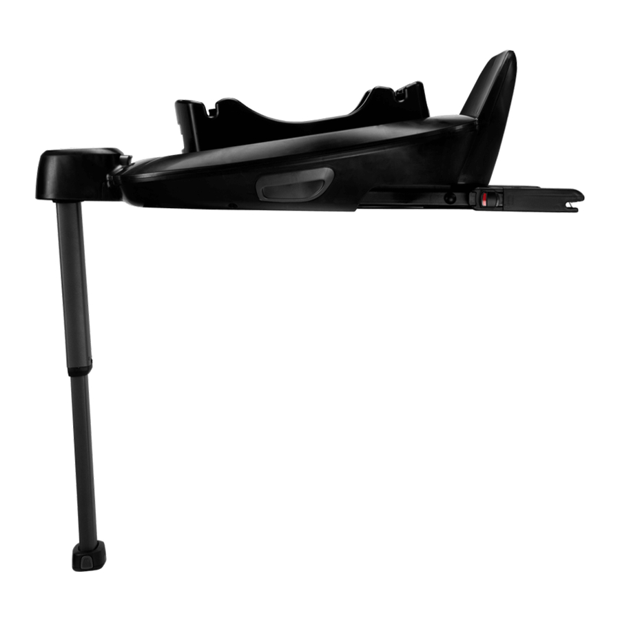
Make sure all parts are available before assembly. If any part is missing, please contact local retailer. No tools are required for assembly.

- ISOFIX Adjuster Button
- Child Restraint Release Button
- Load Leg
- Load Leg Adjustment Button
- ISOFIX Guides
- ISOFIX Connector
- Instruction Manual Storage Compartment
- Infant Carrier Rotation Button
Product Set Up
Installation Concerns
This enhanced child restraint is only suitable for vehicle seats equipped with ISOFIX anchorage bars.

DO NOT install this enhanced child restraint on vehicle seats that face sideways or rearward with respect to the moving direction of the vehicle.

Product Use
Base Installation
- Attach the ISOFIX guides to the vehicle's ISOFIX anchor bars (see vehicle owner's manual). (3) The ISOFIX guides can protect the surface of the vehicle seat from being torn. They can also guide the ISOFIX connectors.

- Unfold the load leg from storage compartment.
![]()
- Extend the ISOFIX connectors by pressing the ISOFIX adjustment button while pulling on the connector.

- Press the ISOFIX adjustment button to adjust the ISOFIX connectors. Line up the ISOFIX connectors with the ISOFIX guides, and then "click" both ISOFIX connectors into the ISOFIX anchor bars.

![warning]() Make sure that both ISOFIX connectors are securely attached to their ISOFIX anchor bars. There should be two audible clicks and the colors of the indicators on both ISOFIX connectors should be completely green. (6)-1
Make sure that both ISOFIX connectors are securely attached to their ISOFIX anchor bars. There should be two audible clicks and the colors of the indicators on both ISOFIX connectors should be completely green. (6)-1
![warning]() Check to make sure the base is securely installed by pulling on both ISOFIX connectors.
Check to make sure the base is securely installed by pulling on both ISOFIX connectors. - After placing the base on the vehicle seat, extend the load leg to the floor (7). When the load leg is installed correctly, the load leg indicator will show green. Red will be shown when installed incorrectly. (7)-2

![warning]() The load leg has multiple positions. When the load leg indicator shows red this means the load leg is in the wrong position.
The load leg has multiple positions. When the load leg indicator shows red this means the load leg is in the wrong position.
![warning]() Make sure the load leg is in full contact with the vehicle floor pan.
Make sure the load leg is in full contact with the vehicle floor pan.
![warning]() Squeeze the load leg adjustment button, then shorten the load leg upwards. (7)-1
Squeeze the load leg adjustment button, then shorten the load leg upwards. (7)-1
The completely assembled base is shown as (8).

![warning]() The ISOFIX connectors must be attached and locked onto the ISOFIX anchor bars. (8)-1
The ISOFIX connectors must be attached and locked onto the ISOFIX anchor bars. (8)-1
![warning]() The load leg must be installed correctly with green indicator. (8)-2
The load leg must be installed correctly with green indicator. (8)-2


 Make sure that both ISOFIX connectors are securely attached to their ISOFIX anchor bars. There should be two audible clicks and the colors of the indicators on both ISOFIX connectors should be completely green. (6)-1

Attaching Infant Carrier to the Base
- Push the enhanced child restraint down onto the base (9), If the enhanced child restraint is secure, the enhanced child restraint indicator will show green. (10)


![warning]() Check that the infant carrier is locked onto the base by pulling up on the handle.
Check that the infant carrier is locked onto the base by pulling up on the handle. - Press the ISOFIX adjustment button and push the base back until it comes in contact with the vehicle seat back.

- Press and hold the rotation button to rotate for easier side loading/ unloading of the child.

- To release the infant carrier, squeeze the infant carrier release button (13)-1, then lift the infant carrier up. (13)-2


Uninstalling the Base
- To remove the base, press the secondary lock button (14)-1 first, followed by the button (14)-2 on the ISOFIX connectors before removing the base from the vehicle seat.

- For transporting, press ISOFIX Adjustment button and move the ISOFIX connectors back into the storage position.


Failure to follow these warnings and instructions could result in serious injury or death.
For proper protection of your child, it is important to use and install BASE next according to the instructions given in this manual.
BASE next is compatible with PIPA next*/ARRA next/TODL next/CARI next.
*For use with PIPA next, please check if below module mark is on the bottom of the shell.

This short instruction is for overview only. For maximum protection and complete information it is essential to read and follow the instruction manual of the following carefully:
Please refer to PIPA next instruction manual for the installation of PIPA next.
Please refer to ARRA next instruction manual for the installation of ARRA next.
Please refer to TODL next instruction manual for the installation of TODL next.
Please refer to CARI next instruction manual for the installation of CARI next.
Contact
Product Registration
Please fill in the above information. The model number and the manufactured date are located at the bottom of BASE next.
To register your product please visit:
www.nunababy.com
Click the "Register Gear" link on the homepage.
For replacement parts, service, or additional warranty questions, please contact our customer service department.
info@nunababy.com
www.nunababy.com
NUNA International B.V.
Van der Valk Boumanweg 178 C
2352JD Leiderdorp
The Netherlands
In the United Kingdom:
infouk@nunababy.com
www.nunababy.com
Documents / Resources
References
Download manual
Here you can download full pdf version of manual, it may contain additional safety instructions, warranty information, FCC rules, etc.
Advertisement


Need help?
Do you have a question about the BASE Next and is the answer not in the manual?
Questions and answers