
Subscribe to Our Youtube Channel
Related Manuals for Powrmatic HEM LX 15-4

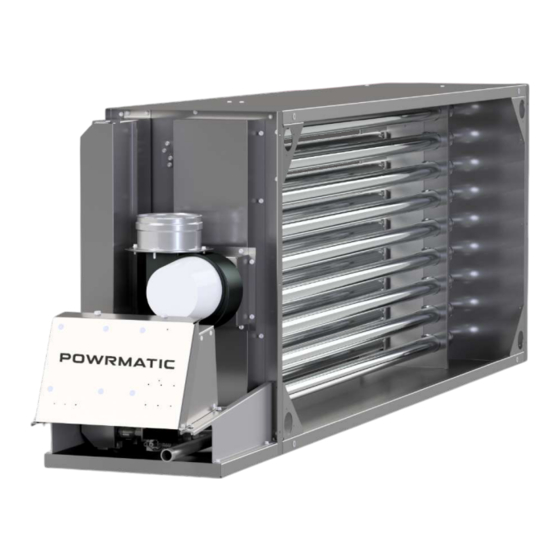
Summary of Contents for Powrmatic HEM LX 15-4
- Page 1 Doc Ref: M109 Issue 1.5 Apr 2022 ® User, Installation & Servicing Manual Issue 1.5 Apr 2022 ErP COMPLIANT J A N U A R Y 2 0 2 1 w w w . p o w r m a t i c . c o . u k...
- Page 2 1. The appliance type and serial number. 2. The original commissioning documentation. As much detail as possible on the fault. 3. Your supplier, or installer, will then contact Powrmatic to make a guarantee claim on your behalf. Conditions of Guarantee 1.
- Page 3 Contents Users, Installation and Servicing Instructions CONTENTS Title Section Contents Page User Instructions Pre Installation Introduction Duties Dimensions Pressure Drop Graphs Technical data General Requirements Installation Fitting the unit Flue System General Identification of Items Electrical Cable Installation Wiring Diagrams Commissioning and Test Procedure Servicing Additional Documents...
- Page 4 User Instructions D) Description of Operation If the unit has not been left operational proceed as follows. Important: The burner must NOT be controlled by switching ON and OFF the A) Checks before operating the HEMX main electrical supply to it. Module 1) Standard Units The main air fan downstream/upstream of the module...
- Page 5 * Gas Safe Registered Engineer All Powrmatic units use gas and electricity to power them, they may also contain moving parts such as pulleys and belts. It would be hazardous to tamper with or attempt to service unless you are a competent person in the field of Gas and Electrical work.
- Page 6 Notes - • ‘Air off’ temperature should not exceed 70°C. If higher air off temperatures are required refer to Powrmatic Limited • The air flow stated above for three HEM-SLx modules in series at an air on temperature of 0°C gives a temperature rise of 70°C otherwise the ‘Air off’ temperature limit would be exceeded.
- Page 7 DIMS A, D & E RELOCATED TO TOHER EDGE OF BULKHEAD DIMS A, D & E RELOCATED TO TOHER EDGE OF BULKHEAD 04/08/2021 HEM-SLx This drawing is copyright and the property of POWRMATIC This drawing is copyright and the property of POWRMATIC UNSPEC. TOLS. DESCRIPTION: UNSPEC.
- Page 8 Pressure Drop Graph HEM LX Airflow m³/h page no. 8 of 52 HEMX Range Users, Installation & Servicing Instructions Doc Ref M109 issue 1.5 Apr 2022.
- Page 9 Pressure Drop Graph HEMSLx 2160 3600 5040 6480 7920 9360 10800 10800 12240 13680 15120 16560 18000 19440 20880 20880 22320 23760 25200 26640 28080 Airflow m³/h 29520 30960 30960 32400 33840 35280 36720 38160 39600 41040 41040 42480 43920 45360 46800 48240...
- Page 10 Burner Gas Rate Burner Gas Rate Pressure (nominal) Pressure (nominal) MODEL Size mm Marked mbar m³/h mbar m³/h HEM LX 15-4 1.67 13.5 1.66 0.80 HEM LX 18-5 1.67 12.0 2.05 0.97 HEM LX 25-5 1.94 14.5 2.90 1.30 HEM LX 30-6 1.94...
- Page 11 Weights HEM- LX Min Air Flow Input Input Module Output Output Packaging (Nett) (Nett) only MODEL m³/s m³/h HEM LX 15-4 15.7 14.4 7.51 0.44 1584 HEM LX 18-5 19.4 17.7 9.16 0.58 2088 HEM LX 25-5 27.4 25.0 12.28 11.7...
- Page 12 Powrmatic units are designed to operate within an appertaining to the area in which the unit is located, ambient temperature range of -10 to 25°C.
- Page 13 1.3.5 Flue System 1.3.7.1. Service Pipes Only flue systems supplied through Powrmatic Ltd may The local gas undertaking should be consulted at the be used with these units and must be installed to current installation planning stage in order to establish the standards and rules in force.
- Page 14 1.3 General Requirements To enable any fluid to be drained off, all modules are These being: fitted with a 'condensate drain point' in the bottom of the Natural Ventilation: There must be permanent air vents exhaust header box. communicating directly with the outside air, at high level and at low level.
- Page 15 High level grille. Free area cm² Free area cm² Free area cm² Free area cm² Free area cm² Free area cm² Free area cm² HEM LX 15-4 15.7 HEM LX 18-5 19.4 HEM LX 25-5 27.4 HEM LX 30-6 33.0 HEM LX 40-8 43.5...
- Page 16 2.1.2. General supported. All Powrmatic modules have been fired, preset and fully tested to stringent approved test procedures prior to 2.1.3 Module Fitment dispatch. Modules are available for: Before installation, check that the: a) Use within an additional casing e.g.
- Page 17 There must be effective sealing between the Please contact the Powrmatic office to obtain the module burner/controls section so that there appropriate bypass dimensions to suit the specific unit. is no air leakage from the main air flow path into the burner/controls section.
- Page 18 Inlets are supplied with models HEM LX 125 to 175, three 40.5 inlets for HEMSLx200). The horizontal flue outlet supplied with the unit must not be used in vertical installations. A vertical specific terminal from the Powrmatic approved 4 HOLES Ø3 system must be used. 40.5...
- Page 19 2.1 Fitting the Unit Horizontal Flue Outlets, Type B Installation Exhaust flue outlet positions are shown in the following diagrams and tables. HEM LX Size ØD 15-4 18-5 25-5 30-6 40-8 HORIZONTAL FLUE POSITION ØD HOLE FOR FLUE SEAL 50-6 60-7 75-9 100-12...
- Page 20 2.1 Fitting the Unit 2.1.7.2 Type C Flued Installations Note: silicone seals supplied are For Type C flued installations, a concentric flue system not water should be used of the appropriate orientation. tight and should not be used in external vertical A CRS calculated maximum The total...
- Page 21 Ensure the trap and any further pipework outside of the air handler unit is made using domestic 32mm waste water Only flue systems supplied through Powrmatic Ltd may fittings to avoid freezing and that the dimensions shown be used with HEMX modules. Twin Wall Flue can also be are adhered to.
- Page 22 2.3 General Identification of Items Burner Controls Compartment Alternate positions for 2nd HIGH LIMIT RESET dual burners only HIGH LIMIT RESET FAULT INDICATION FUSE HIGH FIRE PRESSURE SWITCH OVERHEAT LOW FIRE THERMOSTAT PRESSURE SWITCH MAINS INPUT PACTROL CONTRACTORS BOARD TERMINALS position for 2nd PACTROL BOARD dual burners only...
- Page 23 2.4 Electrical Cable Installation 2.4.1. Electrical Connections Note: To achieve maximum system efficiency it is recommended that units are controlled via a B.M.S. Simple room thermostat and thermostat/time clock control systems will Warning: THIS APPLIANCE MUST BE not provide optimum system efficiency and fuel savings. EARTHED.
- Page 24 2.4 Electrical Cable Installation 2.4.4.1. External Wiring for Modulating Control Warning: External controls MUST be powered via burner terminal 10, 11 and Earth Note: We strongly recommend the use of a suitable screened cable for the 2-core 0-10vdc modulation input on terminals t8/t9. 2.4.4.2.
- Page 25 2.5 Wiring Diagrams 2.5.1. HEM LX 15-100 & HEMSLx 30-75/9 & 100 Single Burner Units page no. 25 of 52 HEMX Range Users, Installation & Servicing Instructions Doc Ref M109 issue 1.5 Apr 2022.
- Page 26 2.5 Wiring Diagrams 2.5.2. HEM LX 125-150 & HEMSLx 75/15-90 & 125-150 Dual Burner Units page no. 26 of 52 HEMX Range Users, Installation & Servicing Instructions Doc Ref M109 issue 1.5 Apr 2022.
- Page 27 2.5 Wiring Diagrams 2.5.3. HEM LX 175-200 & HEMSLx 175-200 Dual Burner Units page no. 27 of 52 HEMX Range Users, Installation & Servicing Instructions Doc Ref M109 issue 1.5 Apr 2022.
- Page 28 * Gas Safe Registered Engineer Lockout is ignition lockout during start up. All Powrmatic modules are fired, preset and fully tested Should an Ignition issue occur during start to stringent approved test procedures prior to dispatch.
- Page 29 2.6 Commissioning and Test Procedure 2.6.3. Air Distribution System 2. Once in standby, press the ENGINEER TEST button on the R2R Main Control board for seconds. (see photo) The system should be checked to ensure that the installation work has been carried out in accordance with the design requirements.
- Page 30 2.6 Commissioning and Test Procedure 2.6.6. Burner Gas Pressure Adjustment This is set for the required heat input before dispatch. High and low gas pressures should be checked in the following manner: Adjustment screw Adjustment nut (10mm) for minimum for maximum pressure pressure setting 1.
- Page 31 2.6 Commissioning and Test Procedure 2.6.6.2. High/Low Burner a. SIT Sigma 843 Adjustment 2.6.6.2.1. High Fire Setting With the burner on low fire and keeping the nut stationary, use a 6 x 1 screwdriver to turn the slotted a. SIT Sigma 843 Adjustment adjustment in to increase and out to decrease, until the required pressure is obtained.
- Page 32 2.6 Commissioning and Test Procedure 7. Press and hold the ENGINEER TEST button for The burner will go into low fire indicated by the LED on top seconds. This will shut the burner down. of the electrical box going to a SLOW FLASH GREEN.
- Page 33 2.6 Commissioning and Test Procedure 2. Check that the BMS and all automatic controls are operating satisfactorily. 2.6.12. Handing over the Unit Hand these instructions to the user or purchaser for retention and instruct in the efficient and safe operation of the unit and associated controls.
- Page 34 2.7 Servicing 4. Release the inlet connection flange from the gas valve by removing the four screws. HEMX units should be serviced once per year. 5. If required remove the manifold by removing the four screws securing it to the burner assembly. Gas Safety (Installation &...
- Page 35 Components from the fan. Only parts supplied via or authorised by Powrmatic 2. Loosen the six screws holding the main control panel, should be used. A short list of parts and part numbers are lift the control panel up and clear of the fixing position detailed in section 3.2 of this manual.
- Page 36 HEM LX 3. Undo two screws retaining the thermostat body and remove thermostat from the panel. Low Fire High Fire HEM LX 15-4 -100 4. Fit replacement thermostat in reverse order. HEM LX 18-5 5. Re-commission the unit. HEM LX 25-5 HEM LX 30-6 2.7.7.5.
- Page 37 2.7 Servicing 2.7.7.6.2 HEMX 60 to 200 Settings (Pa) HEMSLx 1. Disconnect the fan electrical connections from the main terminal strip and the air pressure sensing tube Low Fire High Fire from the fan. HEMSLx 30-6 -190 2. Loosen the six screws holding the main control panel, HEMSLx 45-9 -190 lift the control panel up and clear of the fixing position...
- Page 38 2.7 Servicing 2.7.7.9. Thermistor Model Part number and config no. 1. Disconnect the thermistor from the exhaust fan outlet HEM LX 15-4 142400360-100 2. Disconnect the two pin plug and socket connected HEM LX 18-5 142400360-101 to the end of the red/white cable situated behind the...
- Page 39 3.1 Fault Finding and Status Indication 3.1.1. Burner LED Indication Located on the top of the burner electrical housing Colour / State Fault indication Possible cause of fault On Steady Standby Faulty pressure switch, incorrectly set, 1 Pulse APS1 FAULT incorrectly wired, pick up tube fault.
- Page 40 3.1 Fault Finding and Status Indication 3.1.2. R2R Main Board Indication Located at the bottom left hand corner of the R2R Main Board. Colour State Indication No lockout On steady LOCKOUT Combustion fan OFF Combustion fan Running at speed Slow Flashing FAN FAULT 3.1.3.
- Page 41 3.1 Fault Finding and Status Indication Is there Is the Is there 230V between No call for heat! AMBER LED on <2Vdc between Pactrol controller terminals the electrical panel terminals t8 & Check controller! CON5 - pin 3 and pulsing? Neutral? Module in Overheat.
- Page 42 3.1 Fault Finding and Status Indication Continued from previous page there NOW a Replace spark present Pactrol! at the ignition Electrode? • Ensure spark gap is 2.5mm Is a • Ensure there are no cracks on there spark present and the ceramic NOW a Replace...
- Page 43 3.2 List of Parts Item Description Usage Part No. Gas Valve SIGMA 845 15-50 145035208M-SIT Gas Valve NOVA 827 60-100 145035204M-SIT LX15-100 142423010 LX125-200 Bottom 142423010 LX125-200 Top 142423005 SLx30-75-9 142423010 Ignition Electrode SLx75/15-90 Bottom 142423010 SLx75/15-90 Top 142423005 SLx100 142423010 SLx125-200 Bottom 142423010...
- Page 44 3.2 List of Parts Limit Stat 142403611 146522176 Low Fire Pressure Switch High Fire Pressure switch 146522176 HEM LX 15-18 NVXSTD00501SS HEM LX 25-200 NVXSTD00502SS Swirler (turbulator) HEMSLx 30-200 DHMSL4200102SS 147600155 Tri Coloured Indicator NTC 100k Thermistor 143000860 Temp Range -20 - 210C 'JOX' 230V Relay 143000816 0.37kw 1 to 3Pha Inverter...
- Page 45 3.2 List of Parts HEM LX 15-4 142400360-100 HEM LX 18-5 142400360-101 HEM LX 25-5 142400360-102 HEM LX 30-6 142400360-103 HEM LX 40-8 142400360-104 HEM LX 50-6 142400360-105 HEM LX 60-7 142400360-106 HEM LX 75-9 142400360-107 HEM LX 100-12 142400360-108...
- Page 46 Appendices Appendix 1: HEM LX Information required for ecodesign (ErP) Directive 2009/125 Model 15-4 18-5 25-5 30-6 40-8 Rated Heat Capacity 14.4 17.7 25.0 31.0 39.7 Minimum Heat Capacity 11.7 14.0 14.6 High Fire 82.6 82.4 82.2 81.6 82.2 Gross Efficiency Low Fire 85.1 84.2...
- Page 47 Appendices Appendix 2: HEMSLx Information required for ecodesign (ErP) Directive 2009/125 Model 30-6 45-9 50-6 60-12 Rated Heat Capacity 29.8 45.0 49.7 59.9 Minimum Heat Capacity 14.3 16.9 20.1 High Fire 82.8 82.9 81.7 82.0 Gross Efficiency Low Fire 85.8 84.4 86.3 84.2...
- Page 48 - external location. No specific combustion air requirements - external location. Flue can be front or top. Module supplied with Powrmatic flue terminal and flashing Care must be taken to ensure that flue exit point is not in proximity of windows/doors If necessary flue to be extended to a point where it has clearance from windows/doors.
- Page 49 Stand alone application (ie HEMX not within a secondary housing/ahu etc) Internal location HEMSLx & HEM LX - within open space (ie not plant room) Single module c/w Powrmatic burner enclosure. Combustion air to Powrmatic burner enclosure via Powrmatic combustion air intake grille. Combustion air to space where module is located in accordance with BS6230. Flue can be front or top.
- Page 50 BS6230 Single module c/w Powrmatic burner enclosure. Combustion air ventilation requirements in accordance with BS6230 Plant room ventilation in accordance with BS6230. Flue can be front or top. Powrmatic approved flue to be used. Flue only units - Combustion air to Powrmatic burner enclosure via Powrmatic combustion air intake grille.
- Page 51 Notes: page no. 51 of 52 HEMX Range Users, Installation & Servicing Instructions Doc Ref M109 issue 1.5 Apr 2022.
- Page 52 Energy Association Powrmatic pursues a policy of continues improvement in both design and performance of its products and therefore reserves the right to change, amend or vary specifications without notice. Whilst the details contained herein are believed to be correct they do not form the basis of any contract and interested parties should contact the Company to confirm whether any material alterations have been made since publication of this brochure.
Need help?
Do you have a question about the HEM LX 15-4 and is the answer not in the manual?
Questions and answers