
Subscribe to Our Youtube Channel
Related Manuals for SEW-Eurodrive MOVIPRO PHE11A 30X.E4B-00 Series


Summary of Contents for SEW-Eurodrive MOVIPRO PHE11A 30X.E4B-00 Series
- Page 1 *31973248_0924* Drive Technology \ Drive Automation \ System Integration \ Services Operating Instructions Drive and Application Controller ® MOVIPRO PHE11A-...-30X.E4B-00 Edition 09/2024 31973248/EN...
- Page 2 SEW-EURODRIVE—Driving the world...
- Page 3 Table of Contents Table of Contents General information ........................ 6 About this documentation .................... 6 Structure of the safety notes ................... 6 Decimal separator in numerical values ................ 7 Rights to claim under limited warranty ................ 7 Other applicable documentation .................. 7 Recycling, reprocessing, reuse.................. 7 Product names and trademarks.................. 8 Copyright notice ...................... 8 Safety notes .......................... 9 Preliminary information .................... 9...
- Page 4 Duty cycles........................ 94 Status and error messages................... 95 Fault information ...................... 96 IT security ........................ 97 Service ............................. 99 Inspection/maintenance .................... 99 Device replacement ...................... 99 Status display...................... 100 SEW-EURODRIVE Service .................. 100 Cleaning........................ 100 Shutdown ........................ 101 Storage ........................ 101 Extended storage ....................... 101 IT security guidelines for secure disposal .............. 103 9.10 Waste disposal...................... 104 Technical data ........................ 105...
- Page 5 Table of Contents 10.12 Dimension drawings.................... 118 10.13 Hybrid cable type "D" .................... 120 10.14 Hybrid cable type "E" .................... 122 Index ............................ 124 ® Operating Instructions – MOVIPRO PHE11A-...-30X.E4B-00...
- Page 6 General information About this documentation General information About this documentation The documentation at hand is the original. This documentation is an integral part of the product. The documentation is intended for all employees who perform work on the product. Make sure this documentation is accessible and legible. Ensure that persons respon- sible for the systems and their operation as well as persons who work on the product independently have read through the documentation carefully and understood it.
- Page 7 General information Decimal separator in numerical values 1.2.2 Structure of section-related safety notes Section-related safety notes do not apply to a specific action but to several actions pertaining to one subject. The hazard symbols used either indicate a general hazard or a specific hazard.
- Page 8 General information Product names and trademarks Product names and trademarks The product names mentioned in this documentation are trademarks or registered trademarks of the respective titleholders. Copyright notice © 2024 SEW‑EURODRIVE. All rights reserved. Copyright law prohibits the unautho- rized reproduction, modification, distribution and use of this document – in whole or in part.
- Page 9 Safety notes Preliminary information Safety notes Preliminary information The following general safety notes serve the purpose of preventing injury to persons and damage to property. They primarily apply to the use of products described in this documentation. If you use additional components, also observe the relevant warning and safety notes.
- Page 10 Safety notes Target group Target group Specialist for me- Any mechanical work may be performed only by adequately qualified specialists. Spe- chanical work cialists in the context of this documentation are persons who are familiar with the design, mechanical installation, troubleshooting, and maintenance of the product, and who possess the following qualifications: •...
- Page 11 Safety notes IT security IT security 2.4.1 Contact If you need support with the configuration, contact SEW‑EURODRIVE Service. You can obtain information about the latest security-related problems via e-mail or by visit- ing the Product Security Management webpage. Here you will find various contact op- tions for reporting security-related problems.
- Page 12 Do not use the product as a climbing aid. 2.5.1 Restrictions under the European WEEE Directive 2012/19/EU Options and accessories from SEW-EURODRIVE may only be used in combination with products from SEW-EURODRIVE. ® Operating Instructions – MOVIPRO...
- Page 13 Safety notes Functional safety technology 2.5.2 Restrictions of use The following applications are prohibited unless the device is explicitly designed for such use: • Use in potentially explosive areas. • Use in areas exposed to harmful oils, acids, gases, vapors, dust, and radiation. •...
- Page 14 Safety notes Installation/assembly Installation/assembly Ensure that the product is installed and cooled in accordance with the regulations in the documentation. Protect the product from excessive mechanical strain. The product and its mounted components must not protrude into the path of persons or vehicles. Ensure that no components are deformed or no insulation spaces are modified, particularly during transportation.
- Page 15 Safety notes Startup/operation 2.11 Startup/operation Make sure that any existing transport protection is removed. Do not deactivate monitoring and protection devices of the machine or system, even for a test run. Depending on the degree of protection, products may have live, uninsulated, and sometimes moving or rotating parts as well as hot surfaces during operation.
- Page 16 Device structure Type designation Device structure Type designation ® MOVIPRO drive and application controller ® Motor connection: HAN Q8/0 Signal interfaces: Communication package 1 Advanced Power supply: A = Three-phase current ® T = MOVITRANS Maximum S1 device power: 15 = 1.5 kW (for three-phase current) ® 11 = 1.1 kW (for MOVITRANS Brake control: Control for 3-wire brakes from SEW‑EURODRIVE Design: standard Auxiliary axis connection:...
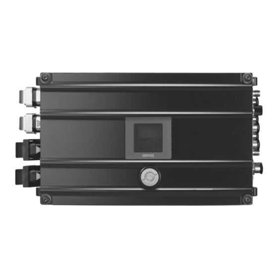
- Page 17 Device structure Scope of delivery Scope of delivery The scope of delivery includes the following components: Component Part number Drive and Application Controller 28318005 ® MOVIPRO PHE11A-...-30X.E4B-00 Protective covers for all plug connectors – Device overview The following figure provides an example of an overview of the most important device components and the position of the labels on the device: 9007225931129227 Nameplate...
- Page 18 Device structure Operating principle Operating principle 3.4.1 Three-phase current power supply The block diagram below shows the basic structure of the device: X4401 X4223 X4233 RS485 DC 24V X5502 DC 24V X2011 X1201 RS485 DC24V X2211/2371 9007219717640459 [A] – Communication and control unit Controller type: MNC45A Integrated service unit [B] – Power supply...
- Page 19 Device structure Operating principle ® 3.4.2 Power supply via MOVITRANS with Ethernet interface The block diagram below shows the basic structure of the device: X4401 X4233 X4223 RS485 DC 24V X5502 DC 24V X1021_1 X1021_2 X2011 RS485 DC24V X2201 36619920907 [A] – Communication and control unit Controller type: MNC45A Service unit...
- Page 20 Device structure Nameplate Nameplate The nameplate lists information about the device type. The following figure shows an example of a nameplate: Type: S0#: Eingang / Input Ausgang / Output D-76646 Bruchsal Made in Germany Status: [10] 51385783307 Product name CE marking RCM mark (depending on device certification) China RoHS-2 marking Data matrix code (with part number and production number)
- Page 21 Product label with QR code. The QR code can be scanned. You will be redirected to the digital services of SEW‑EURODRIVE. There, you have access to product-specific data, documents, and further services. The following figure shows an example of a product label: SEW-EURODRIVE 01.1234567890.0001.20 Digital Services 10690441 35021590539 ®...
- Page 22 Device structure Warning signs Warning signs Caution signs must be attached at various points on the device to warn about particu- lar hazards. Ensure that the following caution signs for identifying hazardous areas are complete and legible: Hazard symbol Meaning Warning of hot surfaces General hazard Warning of dangerous electric voltage...
- Page 23 Device structure Function units 3.8.2 Communication and control unit The function module consists of the following internal elements. Control type The device is equipped with a MNC45A controller. The software is based on the oper- ating system SEWOS from SEW‑EURODRIVE. It is programmed in the high-level lan- ®...
- Page 24 Device structure Function units For further information, refer to chapter "Status and error messages" (→ 2 95) and to the respective project-specific documentation. If you have any queries, contact SEW‑EURODRIVE. Ethernet service interface The Ethernet service interface is used to connect the device to an engineering PC for configuration and maintenance purposes.
- Page 25 Device structure Function units 3.8.3 Power supply The function unit consists of the following internal elements. Devices powered by a three-phase current supply system Power rectifier and line filter Energy is supplied to the device via a three-phase current supply system, a power rec- tifier and a line filter.
- Page 26 Device structure Accessories Accessories 3.9.1 Available accessories If you are unsure about the accessories you require, contact SEW‑EURODRIVE. For further information accessories, refer following documentation: ® "MOVIPRO – Accessories" addendum to operating instructions. The following acces- sories are available for the device: ID module ID module 17974186...
- Page 27 Functional safety Integrated safety technology Functional safety Integrated safety technology 4.1.1 Safe state For safety-related operation of the device, safe torque off is defined as safe condition, see "STO – Safe Torque Off" (→ 2 28). The safety concept is based on this defini- tion.
- Page 28 Functional safety Integrated safety technology 4.1.3 Safety sub-functions STO – Safe Torque Off When the safety sub-function is active, the power supply to the motor is interrupted and the drive cannot generate any torque. This safety sub-function corresponds to a non-controlled stop according to EN 60204‑1, stop category 0.
- Page 29 Functional safety Integrated safety technology This safety sub-function corresponds to a controlled stop of the drive according to EN 60204‑1, stop category 1. ∆t 18014400480359435 = SS1-t safety sub-function monitored = STO safety sub-function active = Speed = Time = Point in time at which SS1-t is activated and motor deceleration is triggered. = Point in time at which STO is activated.
- Page 30 Functional safety Safety requirements • When using the SS1(c) function as described in chapter "Drive safety functions", the brake ramp of the drive is not monitored with respect to safety. In the case of an error, the drive might not be decelerated during the delay time, or it might even be accelerated in the worst case.
- Page 31 Functional safety Safety requirements • Observe the values specified for safety components without fail when designing the safety circuits. • The maximum length for the cable between the safety controller and the device is 30 m. • Do not use the safety-related 24 V supply voltage for feedback. •...
- Page 32 Functional safety Safety requirements • The switching capacity of the safety relays or the relay outputs of the safety con- troller must correspond at least to the maximally permitted, limited output current of the 24 V voltage supply. Observe the manufacturer's instructions concerning the permitted contact loads and fusing that may be required for the safety contacts.
- Page 33 Functional safety Connection variants Connection variants 4.3.1 Basic considerations • For group disconnection, several devices can be provided with 24 V by a single safety relay. The maximum number "n" of devices results from the maximum per- mitted contact rating of the safety relay and the maximum permitted voltage drop of the DC 24 V supply for these devices.
- Page 34 Mechanical installation Requirements Mechanical installation Requirements WARNING Risk of crushing if the load falls. Severe or fatal injuries. • Do not stand under the load. • Secure the area where loads can fall down. • Trained specialists perform the installation. •...
- Page 35 Mechanical installation Mounting position Mounting position The following figure shows permitted and not permitted mounting positions: 18014399541155723 Permitted vertical mounting Impermissible mounting positions ® Operating Instructions – MOVIPRO PHE11A-...-30X.E4B-00...
- Page 36 Mechanical installation Minimum clearance Minimum clearance INFORMATION • Observe the following minimum clearances during installation: – When connecting the cables and plug connectors – When handling the display, diagnostics and operating elements – For heat convection at the cooling fins if the product has cooling fins •...
- Page 37 Mechanical installation Minimum clearance The following figure shows the minimum distances and clearances at all sides of the device: 9007203034276491 Clearance for housing cover Clearance on the side Clearance at bottom of housing X, Y Housing dimensions Cut-out dimensions Clearance at bottom of housing The following table lists the minimum distances and clearances.
- Page 38 Mechanical installation Waste heat Clearance Function Size B: On the side Room for connection cables, > 120 mm plug connectors, mounted ele- ments, and actuator elements such as maintenance switches • = housing dimension C: Bottom of the Room for optimum heat con- X − 50 mm housing vection...
- Page 39 Mechanical installation Installation Installation CAUTION Risk of injury due to sharp edges. Minor injuries. • Wear suitable protective gloves. NOTICE External force too high. Damage to the thread or the screw. • Do not exceed the maximum tightening torque of 3.1 Nm – 3.5 Nm. The following options are available for mechanical mounting: Design Fastening...
- Page 40 Mechanical installation Installation 5.5.1 Fixed angle brackets The following figure shows an example of the main mounting elements and dimen- sions: 377.1 36903174667 Mounting surface Angle bracket Device Tapped holes Mounting the angle brackets Accessories "EMS angle bracket” (part number 28218248): •...
- Page 41 Electrical installation Three-phase current power supply Electrical installation Three-phase current power supply 6.1.1 Installation notes Observe the following points for electrical installation: NOTICE Ground fault at motor or brake output. Damage to property. • During installation, avoid conductive connections between motor and brake out- put and the ground potential.
- Page 42 Electrical installation Three-phase current power supply EMC-compliant installation Ensure that there is a HF-capable equipotential bonding for all drive components. Use low-impedance, HF-capable connectors such as HF litz wire or ground straps. Stan- dard PE conductors do not achieve sufficient equipotential bonding regarding HF and EMC.
- Page 43 Electrical installation Three-phase current power supply 6.1.4 Line components Selecting the residual current device The inverter can cause a direct current in the PE conductor. Proceed as follows to select the residual current device: 1. If using a residual current device is not mandatory according to the standards, SEW‑EURODRIVE recommends not using a residual current device.
- Page 44 Electrical installation Three-phase current power supply Contactors Only use contactors in utilization category AC-3 (EN 60947‑4‑1) as line and brake contactors. ® Operating Instructions – MOVIPRO PHE11A-...-30X.E4B-00...
- Page 45 Electrical installation MOVITRANS® power supply MOVITRANS® power supply 6.2.1 Installation notes NOTICE Ground fault at motor or brake output. Damage to property. • During installation, avoid conductive connections between motor and brake out- put and the ground potential. Observe the following points for electrical installation: •...
- Page 46 Electrical installation MOVITRANS® power supply EMC-compliant installation Ensure that there is a HF-capable equipotential bonding for all drive components. Use low-impedance, HF-capable connectors such as HF litz wire or ground straps. Stan- dard PE conductors do not achieve sufficient equipotential bonding regarding HF and EMC.
- Page 47 Electrical installation UL-compliant installation UL-compliant installation INFORMATION Due to UL requirements, the following chapter is always printed in English, indepen- dent of the language of the documentation. Warnings are also printed in French. 6.3.1 (Field wiring) Power terminals Use 75 °C copper wire only. 6.3.2 Short circuit current rating Suitable for use on a circuit capable of delivering not more than 5000 rms symmetrical...
- Page 48 Electrical installation UL-compliant installation 6.3.4 Motor overload protection The devices are provided with load and speed-sensitive overload protection and thermal memory retention upon shutdown or power loss. The trip current is adjusted to 140 % of the rated motor current. For further informa- tion, refer to chapter "Technical data".
- Page 49 Electrical installation Protective measures against electrical hazards Protective measures against electrical hazards 6.4.1 Overview The following figure is an overview of the preventive measures against electrical haz- ards: Preventive measures according to IEC 60364‑4‑41 Stationary use Mobile use Contactless Contactless Direct Direct energy energy...
- Page 50 Electrical installation Protective measures against electrical hazards Leakage currents Leakage currents ≥ AC 3.5 mA/DC 10 mA may occur during normal operation. To avoid dangerous shock currents in accordance with EN 61800-5-1, strictly observe the following: • The protective earth (PE) connection must meet the requirements for systems with high earth-leakage currents.
- Page 51 Electrical installation Protective measures against electrical hazards Direct power supply The ground connection protects mobile systems with direct power supply against elec- trical hazards. Ensure the ground connection using 2 mobile contact outlets (sliding contacts) or a trailing cable. The following figure shows a sample mobile system with direct power supply via slid- ing contacts: 18014398844514443 Stationary system component...
- Page 52 Electrical installation Protective measures against electrical hazards Equipotential bonding on mobile systems ensures that in case of a fault, no contact voltages occur. The following figure shows a sample mobile system with contactless energy transfer system: 35742672011 Dissipative floor coverings or work Motor areas Line cable...
- Page 53 Electrical installation Protective measures against electrical hazards Discharge measures To ensure optimum protection against electrostatic discharge (ESD) and capacitive coupling, you have to take measures between the mobile component and the station- ary end for dissipating the charges. This is particularly important for mobile systems such as lifting gears, floor conveyor vehicles, or floor conveyor systems.
- Page 54 Electrical installation Motor types Motor types INFORMATION Unsuitable motor monitoring can lead to a malfunction. Only connect motors with thermostat (TH) to the device. The device supports a variety of global motors from SEW‑EURODRIVE. For a list of motor types, refer to chapter "Motor types" (→ 2 110). Observe the possible brake voltage in chapter "Output data" (→ 2 108).
- Page 55 Electrical installation Using prefabricated cables Using prefabricated cables SEW‑EURODRIVE uses prefabricated cables for certifications, type tests and ap- proval of the devices. The cables available from SEW‑EURODRIVE meet all the re- quirements necessary for the functions of the device and the connected components. The devices under consideration are always the basic devices including all compo- nents to be connected and corresponding connection cables.
- Page 56 Electrical installation Connection blocks INFORMATION Some connections depend on the device design. For information regarding the type of connection present at your device, refer to the device designation and the designa- tions of the function units on the nameplates. For further information on function units, refer to chapter "Device structure" (→ 2 16).
- Page 57 Electrical installation Connection blocks 6.9.1 Power supply connection Type designation Connection PHE..A-A..-...B-00 [1] Not used [2] X1201: AC 400 V input ® PHE..A-T..-...B-00 [1] X1021_2: MOVITRANS THM20C pick-up ® [2] X1021_1: MOVITRANS THM20C pick-up 6.9.2 Auxiliary axis connection Type designation Connection PHE..A-A..-..X0..B-00 [1] Not used PHE..A-T..-..X0..B-00 ® PHE..A-A..-..X1..B-00 [1] X2211: MOVIMOT auxiliary axis AC 400 V...
- Page 58 Electrical installation Electrical connections 6.10 Electrical connections 6.10.1 Representation of connections The diagrams show the contact end of the connections. 6.10.2 Connection cables INFORMATION For more information about cable types, see chapter "Technical data" (→ 2 105). Connection cables are not included in the delivery. Prefabricated cables for connect- ing SEW‑EURODRIVE components are available to order.
- Page 59 Electrical installation Electrical connections 6.10.3 Cable structure Diagram The following table shows the cable structure based on an example: Figure Meaning Cable shield Number of core pairs (in twisted cables only) Number of cores G – with protective earth, green-yellow X - without protective earth 0.25 Core cross section in mm...
- Page 60 Electrical installation Electrical connections ® 6.10.4 X1021: MOVITRANS THM20C pick-up Function ® Unit supply with MOVITRANS THM20C pick-up Connection type ® Q 4/2, female Pin assignment Name Function ® THM Pole 1 MOVITRANS pick-up pole 1 n.c. Not connected ® THM Pole 2 MOVITRANS pick-up pole 2 n.c.
- Page 61 Electrical installation Electrical connections 6.10.5 X1201: AC 400 V input Function AC 400 V input to supply devices up to 16 kW Connection type ® Q 4/2, male Pin assignment 4 PE Name Function Supply system phase 1 Supply system phase 2 Supply system phase 3 n.c.
- Page 62 Electrical installation Electrical connections Cable Length/installation Component type Part number: 18150306 Cable design: (4G2.5) Variable length – ® ® Q 4/2 ↔ Han Q 4/2 male Part number: 18174213 Cable design: (4G2.5) Variable length – ® Q 4/2 ↔ Open with conductor end sleeves Part number: 18174221 Cable design: 4G2.5 Only permitted for decentralized supply units with...
- Page 63 Electrical installation Electrical connections 6.10.6 X2011: Motor with brake control INFORMATION To avoid damage or malfunction of the drive system, do not use motors with built-in brake rectifier in conjunction with this product. Function Power connection for motor with brake up to 4 kW Connection type ®...
- Page 64 Electrical installation Electrical connections Connection cables The following table shows the cables available for this connection. The cables are ap- proved up to 2.2 kW according to IEC / UL. Cables Length/ Component installation type Part number: 18125794 DRS71 – 90 Variable DRE80 –...
- Page 65 Electrical installation Electrical connections Conductor assignment Part number Signal name Color coding Black/U1 Black/V1 Black/W1 Black/1 18125794 Black/2 18143776 Black/3 Black/4 Black/5 PE connection Green-yellow + shield end (Inner shield) Connecting the hybrid cable The following figure shows the connection of the hybrid cable to the terminal box of the motor.
- Page 66 Electrical installation Electrical connections ® 6.10.7 X2201: MOVIMOT auxiliary axis Function ® Power connection for MOVIMOT auxiliary axis with DC 560 V supply Connection type ® Q 8/0, female Pin assignment Name Function DC link (+) n.c. Not connected DC link (-) +24V DC 24 V output Reference potential...
- Page 67 Electrical installation Electrical connections Cables Length/installation Component type ® Part number: 18224520 Variable length MOVIMOT MM 03D‑503‑00 – Cable design: 4G1.5+(3X0.75)+(2X0.75) MM 22D‑503‑00 ® Q 8/0 ↔ APGX ® The following figure shows an example of the wiring of an external MOVIMOT with DC supply: X2201 ®...
- Page 68 Electrical installation Electrical connections ® 6.10.8 X2211: MOVIMOT auxiliary axis Function ® Power connection for MOVIMOT auxiliary axis with AC 400 V supply Connection type ® Q 8/0, female Pin assignment Name Function Supply system phase 1 Coding pin Supply system phase 3 +24V DC 24 V output Reference potential...
- Page 69 Electrical installation Electrical connections Cables Length/installation Component type ® Part number: 18123511 Variable length MOVIMOT MM 03D‑503‑00 – Cable design: 4G1.5+(3X0.75)+(2X0.75) MM 22D‑503‑00 ® ® Q 8/0 ↔ Han Q 8/0 ® The following figure shows an example of the wiring of an external MOVIMOT with DC supply: X2211 ®...
- Page 70 Electrical installation Electrical connections 6.10.9 X2371: AC 400 V output Function AC 400 V output to supply external devices Connection type ® Q 4/2, female Pin assignment Name Function Supply system phase 1 Supply system phase 2 Supply system phase 3 n.c. Not connected n.c.
- Page 71 Electrical installation Electrical connections Conductor assignment Part number Signal name Conductor color Black/U Black/V 18150187 Black/W Green-yellow ® Operating Instructions – MOVIPRO PHE11A-...-30X.E4B-00...
- Page 72 Electrical installation Electrical connections 6.10.10 X4001: RS485 interface – system bus Function Internal RS485 interface (system bus) Connection type M12, 5-pin, female, B-coded Pin assignment Name Function +24V DC 24 V output RS485 data line (-) Reference potential RS485 data line (+) res.
- Page 73 Electrical installation Electrical connections 6.10.11 X4011: RS485 interface – external Function RS485 interface for external components Connection type M12, 5-pin, female, B-coded Pin assignment Name Function +24V DC 24 V output RS485 data line (-) Reference potential RS485 data line (+) res.
- Page 74 Electrical installation Electrical connections 6.10.12 X4101: CAN bus – system bus INFORMATION If there is no station connected here, you must terminate the bus with a 120 Ω resis- tor. Function CAN system bus – output Connection type M12, 5-pin, female, A-coded Pin assignment Name Function...
- Page 75 Electrical installation Electrical connections Connection cables Cables Length/installation Component type Standard lengths: 1 m: Part number: 13237748 2 m: Part number: 13237756 3 m: Part number: 13286315 4 m: Part number: 13286323 5 m: Part number: 13286331 10 m: Part number: 13286358 15 m: Part number: 13286366 Fixed length Custom lengths: –...
- Page 76 Electrical installation Electrical connections Conductor assignment Part number Signal name Color coding 13281348 CAN_SHLD – 13281356 +24V 13281364 Black 13281372 CAN_H White 13281380 CAN_L Blue 13281399 13281402 13281410 13281429 Connection components CAN T-piece Part number: 13290967 Connection: M12 9007204911485067 CAN terminating resistor Part number: 13287036 Connection: M12 22822010891...
- Page 77 Electrical installation Electrical connections 6.10.13 X4111: CAN bus – external INFORMATION If there is no station connected here, you must terminate the bus with a 120 Ω resis- tor. Function CAN bus for external components Connection type M12, 5-pin, female, A-coded Pin assignment Name Function...
- Page 78 Electrical installation Electrical connections Connection cables Cables Length/installation Component type Standard lengths: 1 m: Part number: 13237748 2 m: Part number: 13237756 3 m: Part number: 13286315 4 m: Part number: 13286323 5 m: Part number: 13286331 10 m: Part number: 13286358 15 m: Part number: 13286366 Fixed length Custom lengths: –...
- Page 79 Electrical installation Electrical connections Conductor assignment Part number Signal name Color coding 13281348 CAN_SHLD – 13281356 +24V 13281364 Black 13281372 CAN_H White 13281380 CAN_L Blue 13281399 13281402 13281410 13281429 Connection components CAN T-piece Part number: 13290967 Connection: M12 9007204911485067 CAN terminating resistor Part number: 13287036 Connection: M12 22822010891...
- Page 80 Electrical installation Electrical connections 6.10.14 X4223: Ethernet service interface Function Ethernet service interface of the communication and control unit Connection type Ethernet RJ45 Pin assignment Name Function Sending cable (+) Sending cable (-) Receiving cable (+) res. Reserved res. Reserved Receiving cable (-) res.
- Page 81 Electrical installation Electrical connections 6.10.15 X4233: Ethernet fieldbus Function Ethernet fieldbus interface, 4-pin Connection type M12, 4-pin, female, D-coded Pin assignment Name Function Sending cable (+) Receiving cable (+) Sending cable (-) Receiving cable (-) Connection cable Cable Length/installation Component type Part number: 19105401 Cable design: (2X2X0.14)
- Page 82 Electrical installation Electrical connections 6.10.16 X4401: ID module Function Interface for ID module from SEW‑EURODRIVE Connection type M12, 5-pin, male, A-coded Pin assignment Name Function Reference potential IDM-Data ID module data line res. Reserved res. Reserved res. Reserved Connection component ID module Part number: 17974186 Connection M12...
- Page 83 Electrical installation Electrical connections 6.10.17 X5002_1: Digital inputs/outputs – communication and control unit Function Digital inputs/outputs of the communication and control unit Connection type M12, 5-pin, female, A-coded Pin assignment Name Function +24V DC 24 V output DI01/DO01 Data reception direction 02/Digital output 02 Reference potential DI00/DO00 Data reception direction 01/Digital output 01...
- Page 84 Electrical installation Electrical connections 6.10.18 X5002_2: Digital inputs/outputs – communication and control unit Function Digital inputs/outputs of the communication and control unit Connection type M12, 5-pin, female, A-coded Pin assignment Name Function +24V DC 24 V output DI03/DO03 Data reception direction 04/Digital output 04 Reference potential DI02/DO02 Data reception direction 03/Digital output 03...
- Page 85 Electrical installation Electrical connections 6.10.19 X5003: Digital input – communication and control unit Function Digital input of communication and control unit Connection type M12, 8-pin, female, A‑coded Pin assignment Name Function DI04/DO04 Digital input 05/Digital output 05 DI05/DO05 Data reception direction 06/Digital output 06 DI06/DO06 Data reception direction 07/Digital output 07 DI07/DO07...
- Page 86 Electrical installation Electrical connections 6.10.20 X5502: Safe disconnection – input INFORMATION To avoid non safety-related shutdown, jumper this connection only if the product will not perform any safety functions according to EN ISO 13849-1. INFORMATION Use only shielded cables for this connection. This connection is marked with a yellow ring.
- Page 87 Electrical installation Electrical connections Cable Length/installation Component type Part number: 28129253 Terminal box of the safety Cable design: (2x0.75) relay/safety controller Variable length M12, 5-pin, male, A‑coded ↔ M12, 5-pin, male, A‑coded Connection component STO jumper plug Part number: 11747099 Structure: bridged 1+4/2+3 Connection: M12 72057595186840843 ®...
- Page 88 Startup For your safety Startup For your safety NOTICE Danger due to arcing. Damage to electrical components. • Do not disconnect power connections during operation. • Do not connect power connections during operation. INFORMATION To ensure fault-free operation, do not disconnect or connect signal cables during operation.
- Page 89 Startup Startup procedure Startup procedure During startup, the different components of the device are parameterized and/or in- stalled. The following step-by-step instructions give an overview of the device startup procedure and lists other applicable documentation: 1. Accept the Ethernet configuration of the device using the ID module. For more in- formation, refer to chapter "Applying the Ethernet configuration using the ID module" (→ 2 89).
- Page 90 Startup Startup procedure 9007230763005963 ü Make sure the device is switched off. 1. Connect the ID module to the connection X4401. 2. Switch on the device. ð The ID module is read out by the boot loader that is installed on the device. The Ethernet configuration is transferred to the device.
- Page 91 Startup Startup procedure 1. Establish a connection to the device. Use the Wi-Fi infrastructure or connect the device using the X4223 connection. 2. Load the user program onto the MNC45A controller as shown in the following fig- ure. For further information on software management, refer to the following docu- ®...
- Page 92 Startup Addresses of the frequency inverters ® For more information on starting up an external MOVIMOT drive, click here: ® • "MOVIMOT MM..C" operating instructions ® • "MOVIMOT MM..D" operating instructions Addresses of the frequency inverters The device is delivered with the following frequency inverter addresses: Frequency inverter SBus address Axis 1 (internal axis)
- Page 93 Operation For your safety Operation For your safety WARNING Electric shock due to charged capacitors. Severe or fatal injuries. • Observe a minimum switch-off time after disconnecting the supply voltage: 10 minutes. CAUTION Risk of burns due to hot surfaces of the device or connected options, e.g. braking re- sistors.
- Page 94 Operation Duty cycles Duty cycles 8.3.1 Duty type S1 Continuous duty: Operation with a constant loading condition, the motor achieves a thermal steady state. P, ϑ ϑ ϑ 2325833867 8.3.2 Duty type S2 Short-time duty: Operation at constant loading condition for a limited, given time fol- lowed by a time at rest.
- Page 95 Operation Status and error messages Status and error messages The device’s status display shows the current operating status. There are two kinds of status and error messages: from the device and from the user program. Status and error messages from the device are issued when no user program is active. For more information on possible status and error messages of the user program, refer to the respective project-specific documentation.
- Page 96 Operation Fault information Fault information 8.5.1 For your information If the application reports a failure, the respective error number of the highest prioritized error is displayed on the status display of the device or on the PZO display unit. Two error states are distinguished: •...
- Page 97 Operation IT security 8.5.3 Acknowledging fault messages The drive may restart automatically depending on the setting after fault elimination or after a reset. Establish a safe working environment before eliminating a fault if auto- matic restart of the driven machine is not permitted for safety reasons. Manual reset To perform a manual reset, switch off the voltage supply.
- Page 98 Operation IT security • Regularly check which Security Advisories are available in the Online Support of SEW‑EURODRIVE. • Evaluate the fault memories and diagnostics information of your products regularly and check whether there are entries that affect IT security. 8.6.2 Guidelines for secure operation Various service accesses can be activated on the device.
- Page 99 Service Inspection/maintenance Service Inspection/maintenance INFORMATION Never open the device. Only SEW‑EURODRIVE may perform repairs. The device is maintenance-free. SEW‑EURODRIVE does not stipulate any regular in- spection work. However, it is recommended that you check the following components regularly: • Connection cables: If cables become damaged or fatigued, replace them immediately.
- Page 100 For more information refer to chapter "Status and error messages" (→ 2 95) and to the documentation on the user program (for the respective system solution). If you have any queries, contact SEW‑EURODRIVE. SEW-EURODRIVE Service If you are unable to rectify a fault, contact SEW‑EURODRIVE Service. For addresses, refer to www.sew‑eurodrive.com.
- Page 101 Service Shutdown Shutdown WARNING Electric shock due to charged capacitors. Severe or fatal injuries. • Observe a minimum switch-off time after disconnecting the supply voltage: 10 minutes. To shut down the device, disconnect it from the power supply using appropriate mea- sures.
- Page 102 Service Extended storage If the 4-year cycle is neglected, SEW‑EURODRIVE recommends connecting the ® device to a MOVITRANS supply with reduced line cable current. To do so, set the ® Nominal line cable current parameter in the MOVITRANS supply according to the fol- lowing overview to slowly increase the internal voltage supply: The following graduations are recommended: •...
- Page 103 Service IT security guidelines for secure disposal IT security guidelines for secure disposal 9.9.1 Removing the product from its intended environment If the data stored on the product is considered relevant for IT security, remove it as de- scribed in the section "Secure removal of data stored in the product." (→ 2 103) 9.9.2 Removing reference and configuration data in the environment Reference files, configuration files, log files, and other data belonging to the product...
- Page 104 Service Waste disposal 9.10 Waste disposal Dispose of the product and all parts separately in accordance with their material struc- ture and the national regulations. Put the product through a recycling process or con- tact a specialist waste disposal company. If possible, divide the product into the follow- ing categories: •...
- Page 105 Technical data Marks Technical data 10.1 Marks 10.1.1 Basic device The device complies with the following regulations and guidelines: Mark Definition The CE marking indicates compliance with the following European direc- tives: • Low Voltage Directive 2014/35/EU • EMC Directive 2014/30/EU •...
- Page 106 Technical data General 10.2 General Basic device Type designation PHE..A-A...-...B-00 PHE..A-T..-...B-00 Interference immunity Complies with EN 61800-3 Interference suppression level A according to EN 55011 Interference emission Limit value class C3 according to Limit value class C3 according to EN 61800-3 EN 61800-3 for interference emis- sion Ambient temperature without +5 to +40 °C (non-condensing)
- Page 107 Technical data Current reduction (derating) 10.3 Current reduction (derating) The following diagram shows how to reduce the output current in dependence of in- stallation altitude and ambient temperature for a PWM of 4 kHz. Refer to chapter "Technical data" (→ 2 105) for a detailed description of the parameters. Also observe the "Restrictions of use" (→ 2 13) and the reduction of the line voltage by 6 V per 100 m.
- Page 108 Technical data Input data 10.4 Input data Input data X1201 X1021_1/1021_2 Type designation PHE..A-A...-...B-00 PHE..A-T..-...B-00 ® Power supply Three-phase current MOVITRANS (THM20C008 pick-up) Nominal input voltage 3 × AC 380 – 500 V AC 150 – 350 V Nominal input current AC 3.5 A AC 2.3 A Nominal input frequency 50 – 60 Hz 25 kHz Maximum permitted rated 5 kA short-circuit current at the line input of the device...
- Page 109 Technical data Axis data 10.6 Axis data Motor with brake control X2011 Axis type MM15D Nominal output power 1.5 kW (2.0 HP) Nominal output current AC 4.0 A Current limiting AC 6 A, motor mode Duration depends on the capacity utilization Output voltage 3 × AC 0 – 500 V PWM frequency Adjustable: 4/8/16 kHz Output frequency...
- Page 110 Technical data Motor types 10.7 Motor types The device supports the following global motors from SEW‑EURODRIVE: Power rat- Motor types Brake, Brake, op- standard tion 0.25 kW DT63L4, 50 Hz, 400 V (IEC) BR03 – DR63L4, 50/60 Hz (global) BR03 – DRN71MS4, 50/60 Hz (global) BE03 BE05 DR63L4, 50 Hz, 400 V (IEC)
- Page 111 Technical data Motor types Power rat- Motor types Brake, Brake, op- standard tion 0.55 kW DT80K4, 50 Hz, 400 V (IEC) BMG1 – DZ80K4, 60 Hz, 380 V (ABNT) – BMG1 DRS71M4, 60 Hz, 380 V (ABNT) BE05 DRS71M4, 50/60 Hz (global) BE05 DRN80MK4, 50/60 Hz (global) BE05 DRS71M4, 50 Hz, 400 V (IEC) BE05 DRS71M4, 60 Hz, 460 V (IEC) BE05...
- Page 112 Technical data Motor types Power rat- Motor types Brake, Brake, op- standard tion 1.1 kW DT90S4, 50 Hz, 400 V (IEC) BMG2 – DZ90S4, 60 Hz, 380 V (ABNT) – BMG2 DRE80M4, 60 Hz, 380 V (ABNT) DRE90M4, 50/60 Hz (global) DRN90S4, 50/60 Hz (global) DRS80M4, 50 Hz, 400 V (IEC) DRS80M4, 60 Hz, 460 V (IEC) DRE90M4, 50 Hz, 400 V (IEC) DRE90M4, 60 Hz, 460 V (IEC)
- Page 113 90;100 2.48 (1) Power loss in 12.0 standby (2) Efficiency level according to IEC 61800‑9‑2 (3) Manufacturer SEW-EURODRIVE GmbH & Co KG RG Mannheim, HRB 230207 D-76646 Bruchsal (5) Apparent out- 2.77 put power (6) Indicative mo- 1.50 tor rated power...
- Page 114 Technical data Auxiliary axes 10.9 Auxiliary axes ® MOVIMOT auxiliary axis X2211 X2201 Power connection AC 380 – 500 V DC 600 V Nominal output voltage Power connection 16 A 10 A Current limiting Tripping characteristic T for in- tegrated fuses Electronic supply DC 24 V (-15% – +20%) Nominal output voltage Electronic supply 1.4 A Current limiting...
- Page 115 Technical data Communication and control unit 10.10 Communication and control unit 10.10.1 Control type INFORMATION The overall output power of the 24 V voltage supply at the plug connectors for buses and digital inputs/outputs must not exceed 48 W. Type MNC45A Engineering Engineering is performed via the Ethernet service interface and the plant ®...
- Page 116 Technical data Communication and control unit 10.10.2 Ethernet fieldbus interface Ethernet fieldbus interface X4233 Transmission rate 10/100 Mbit/s Properties Half/full duplex, auto negation, auto crossover Maximum cable length 100 m according to IEEE 802.3 10.10.3 CAN interfaces CAN interfaces X4101/X4111 General According to CAN specification 2.9, parts A and B Transmission technology according to ISO 11898 A maximum of 64 stations Baud rate...
- Page 117 Technical data Safety technology 10.11 Safety technology 10.11.1 General Information Safety characteristics Approved safety classes of the device Performance level d according to EN ISO 13849‑1 Probability of a dangerous failure per 0 (fault exclusion) hour (PFH value) Service life 20 years After that, you must replace the device. Safe state Safe torque off (STO) 10.11.2 STO interfaces...
- Page 118 Technical data Dimension drawings 10.12 Dimension drawings 10.12.1 Basic device INFORMATION For the connections, connection cables and connected components, observe a clear- ance of 120 mm to the side. The dimension drawing shows the mechanical dimensions in mm: 37.5 377.1 400.1 127.5 9007236157918091 ®...
- Page 119 Technical data Dimension drawings 10.12.2 Mounting bracket 9007211204068235 ® Operating Instructions – MOVIPRO PHE11A-...-30X.E4B-00...
- Page 120 Technical data Hybrid cable type "D" 10.13 Hybrid cable type "D" 10.13.1 Mechanical design GNYE 5436771083 [1] Shield Cable type D/1.5 D/2.5 D/4.0 D/6.0 D/10.0 18110886 11747013 18119573 11747021 11747048 Supply cores 4 × 1.5 mm 4 × 2.5 mm 4 × 4.0 mm 4 ×...
- Page 121 Technical data Hybrid cable type "D" 10.13.2 Properties All cable types have the following properties: • Maximum 600 V operating voltage for all cores • Approved according to European and American standards • Suitable for cable carriers: – Bending cycles > 5 million –...
- Page 122 Technical data Hybrid cable type "E" 10.14 Hybrid cable type "E" 10.14.1 Mechanical design 5436773643 [1] Shielded "three-conductor" cable [2] EMC shielding, "three-conductor" cable [3] Plaiting for complete EMC shielding Cable type E/1.5 E/2.5 E/4.0 E/6.0 01768948 01768956 00150509 00150630 Supply cores 4 ×...
- Page 123 Technical data Hybrid cable type "E" 10.14.2 Properties All cable types have the following properties: • Maximum 600 V operating voltage for all cores • Approved according to European and American standards • Suitable for cable carriers: – Bending cycles > 5 million –...
- Page 124 Index Index Installation altitude ........ 13, 107 Copyright notice ............. 8 Accessories ............ 26 Acknowledging fault messages ...... 97 Angle bracket ............ 40 Decimal separator.......... 7 Assembly Derating ............... 13 Safety notes ........... 14 Diagram ............ 107 Designated use ............ 12 Device Block diagram.......... 18, 19 Shutting down the device...... 101 Brake control ............
- Page 125 Index Functional safety technology Minimum clearance.......... 36 Safety note ............. 13 Motor types ............ 22, 54 Fuse .............. 43 Mounting position.......... 35 ® MOVIMOT ............ 22 ® MOVITRANS mobile converter ...... 25 Ground connection ........ 49, 50 Grounded star point.......... 41 Nameplate ............ 20 Nomenclature ............ 16 Hybrid cables............
- Page 126 Index Safety notes Motor types ........... 110 Assembly............ 14 Output data ........... 108 Designation in the documentation .... 6 RS485 interfaces .......... 116 Installation ............ 14 Safety technology ......... 117 Installation altitude > 1000 m ...... 13 TN system............ 41 Operation............ 15 Trademarks............ 8 Preliminary information........ 9 Transport ............. 13 Startup............
- Page 128 SEW-EURODRIVE—Driving the world SEW-EURODRIVE GmbH & Co KG Ernst-Blickle-Str. 42 76646 BRUCHSAL GERMANY Tel. +49 7251 75-0 Fax +49 7251 75-1970 sew@sew-eurodrive.com www.sew-eurodrive.com...
Need help?
Do you have a question about the MOVIPRO PHE11A 30X.E4B-00 Series and is the answer not in the manual?
Questions and answers