Advertisement
Available languages
Available languages
Quick Links
PROJECT SOURCE and logo design are trademarks
or registered trademarks of LF, LLC. All rights reserved.
Serial Number
Purchase Date
Thank you for purchasing this PROJECT SOURCE product.
Questions, problems or missing parts?
Before returning, contact us on:
866-389-8827, 8 a.m. - 8 p.m., EST, Monday - Sunday or ascs@lowes.com.
SG24780
ITEM # 6270527
MODEL # 7140-70-PS
VENTILATION FAN
Español p. 13
ATTACH YOUR RECEIPT HERE
06/2024
Advertisement

Related Manuals for LF PROJECT SOURCE 7140-70-PS


Summary of Contents for LF PROJECT SOURCE 7140-70-PS
- Page 1 VENTILATION FAN Español p. 13 ATTACH YOUR RECEIPT HERE PROJECT SOURCE and logo design are trademarks or registered trademarks of LF, LLC. All rights reserved. Serial Number Purchase Date Thank you for purchasing this PROJECT SOURCE product. Questions, problems or missing parts? Before returning, contact us on: 866-389-8827, 8 a.m.
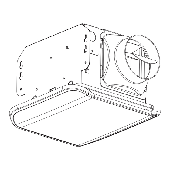
- Page 2 TABLE OF CONTENTS Product Specifications ........................2 Package Contents ..........................2 Hardware Included ..........................2 Safety Information ..........................3 Preparation ............................3 New Construction Installation ......................5 Existing Construction Installation......................7 Care and Cleaning..........................11 Troubleshooting ..........................12 Warranty ............................12 PRODUCT SPECIFICATIONS Airflow: 70 CFM Duct diameter: 4 in. Sound output: 2.0 sones Motor power consumption: 25 Watts 120 V, 60 Hz...
- Page 3 SAFETY INFORMATION Please read and understand this entire manual before attempting to assemble, operate or install the product. • Always disconnect the power supply prior to servicing the fan, WARNING: To reduce the risk of fire, electric shock, motor or junction box. or injury to persons, observe the following: •...
- Page 4 PREPARATION (Continued) Inspect duct work and wiring before proceeding with installation. Before installation, provide inspection and future maintenance access at a location that will not interfere with installation work. Installation may vary depending on how the previous ventilation fan was installed. Supplies necessary for the installation of your bath fan are not all included;...
- Page 5 NEW CONSTRUCTION INSTALLATION BEFORE INSTALLATION WARNING: RISK OF ELECTRIC SHOCK! Ensure the electricity to the wires you are working on is shut off. Either remove the fuse or turn off the circuit breaker before removing the existing bath fan or installing the new one.
- Page 6 NEW CONSTRUCTION INSTALLATION (Continued) 4. Remove the wiring box cover from the fan housing (A) with a Phillips screwdriver (not included). Remove the wiring knockout from the wiring box cover with a flathead screwdriver (not included). Wiring box cover Wiring box cover 5.
- Page 7 EXISTING CONSTRUCTION INSTALLATION BEFORE INSTALLATION WARNING: RISK OF ELECTRIC SHOCK! Ensure the electricity to the wires you are working on is shut off. Either remove the fuse or turn off the circuit breaker before removing the existing bath fan or installing the new one.
- Page 8 EXISTING CONSTRUCTION INSTALLATION INSTRUCTIONS (Continued) 5. Remove the three screws on the side of the fan housing (A) that hold the fan motor in place. Unplug the fan motor, press the sides of the housing slightly outward, and pull the fan motor out of the fan housing (A).
- Page 9 EXISTING CONSTRUCTION INSTALLATION (Continued) 9. With the wiring and duct connected, insert the fan housing (A) through the existing hole in the drywall. Position the fan housing (A) so the bottom edge of the fan housing (A) is flush with the ceiling board. 10.
- Page 10 EXISTING CONSTRUCTION INSTALLATION (Continued) 12. Attach the grille (B) by pinching the mounting springs and inserting them into the narrow rectangular slots in the fan housing (A). Turn on power source. Check the fan for any abnormal sounds or vibrations. Mounting springs Housing...
- Page 11 (Continued) CARE AND CLEANING 2. Remove dust and dirt from the fan housing (A) with a vacuum cleaner. 3. Wipe the fan housing (A) with a damp cloth and wipe dry. 4. Attach the grille (B) by pinching the mounting springs and inserting them into the narrow rectangular slots in the fan housing (A).
- Page 12 LIMITED 5-YEAR WARRANTY If this product fails due to a defect in materials or workmanship at any time during the first FIVE years of ownership, the manufacturer will replace it free of charge, postage-paid at their option. This warranty does not cover products that have been abused, altered, damaged, misused, cut or worn.
- Page 13 MODELO # 7140-70-PS VENTILADOR ADJUNTE SU RECIBO AQUÍ PROJECT SOURCE y el diseño del logotipo son marcas comerciales o marcas registradas de LF, LLC. Todos los derechos reservados. Número de serie Fecha de compra Gracias por comprar este producto PROJECT SOURCE.
- Page 14 TABLA DE CONTENIDO Especificaciones del producto ......................14 Contenidos del paquete........................14 Materiales incluidos ..........................14 Información de seguridad .........................15 Preparación ............................15 Instalación en construcciones nuevas ....................17 Instalación en construcciones existentes ..................19 Cuidado y limpieza ...........................23 Solución de problemas ........................24 Garantía............................24 ESPECIFICACIONES DEL PRODUCTO Flujo de aire: 1.98 m /min (70 CFM) Diámetro del conducto: 4 pulg.
- Page 15 INFORMACIÓN DE SEGURIDAD Lea y comprenda este manual en su totalidad antes de intentar de ensamblar, operar o instalar el producto. • Siempre desconecte la fuente de alimentación antes de darle ADVERTENCIA: para reducir el riesgo de incendio, servicio al ventilador, motor o caja eléctrica. choque eléctrico o lesiones a las personas, respete lo siguiente: •...
- Page 16 PREPARACIÓN (Continuación) Inspeccione los conductos y el cableado antes de proceder con la instalación. Antes de la instalación, proporcione acceso para la inspección y el mantenimiento en un lugar que no interfiera con el trabajo de instalación. La instalacion puede variar dependiendo de cómo se instaló el ventilador anterior. Los suministros necesarios para la instalación de su ventilador no están todos incluidos;...
- Page 17 INSTALACIÓN EN CONSTRUCCIONES NUEVAS PREVIO A LA INSTALACIÓN ADVERTENCIA: ¡RIESGO DE DESCARGA ELÉCTRICA! Asegúrese de cortar el suministro eléctrico en los cables con los que trabajará. Extraiga los fusibles o apague el cortacircuitos antes de quitar el ventilador de baño existente o instalar uno nuevo. 1.
- Page 18 INSTALACIÓN EN CONSTRUCCIONES NUEVAS (Continuación) 4. Retire la tapa de la caja de cableado de la carcasa del ventilador (A) con un destornillador de punta Phillips (no se incluyen). Quite el orifico ciego de cableado de la tapa de la caja de cableado con un destornillador de punta plana (no se incluyen).
- Page 19 INSTALACIÓN EN CONSTRUCCIONES EXISTENTES PREVIO A LA INSTALACIÓN ADVERTENCIA: ¡RIESGO DE DESCARGA ELÉCTRICA! Asegúrese de cortar el suministro eléctrico en los cables con los que trabajará. Extraiga los fusibles o apague el cortacircuitos antes de quitar el ventilador de baño existente o instalar uno nuevo. 1.
- Page 20 INSTALACIÓN EN CONSTRUCCIONES EXISTENTES (Continuación) 4. Acople el conector del conducto (C) a la carcasa del ventilador (A). NOTA: retire la cinta protectora de la aleta del conector del conducto (C). 5. Retire los tres tornillos en el lado de la carcasa del ventilador (A) que sujetan el motor del ventilador en su lugar.
- Page 21 INSTALACIÓN EN CONSTRUCCIONES EXISTENTES (Continuación) 8. Conecte un conducto circular de 4 pulg. al conector del Conector de conducto en la carcasa del ventilador (A), asegurándolo con conducto cinta adhesiva o una abrazadera. Ventile el conducto hacia el Conducto de 4 pulg. exterior.
- Page 22 INSTALACIÓN EN CONSTRUCCIONES EXISTENTES (Continuación) 12. Fije la rejilla (B) apretando los resortes de montaje e insertán- dolos en las ranuras rectangulares estrechas en la carcasa del ventilador (A). Encienda la fuente de alimentación. Pruebe el ventilador en busca de sonido o vibración anormales. Resortes de montaje Ranuras...
- Page 23 CUIDADO Y LIMPIEZA (Continuación) 2. Use una aspiradora para eliminar el polvo y la suciedad de la carcasa del ventilador (A). 3. Limpie la carcasa del ventilador (A) con un paño húmedo y seque con un paño. 4. Una los conectores para la luz LED de la carcasa del ventilador (A) a la rejilla (B).
- Page 24 GARANTÍA LIMITADA DE 5 AÑOS Si el ventilador falla debido a un defecto en el material o la mano de obra en cualquier momento durante los primeros CINCO años de poseerlo, elfabricante lo reemplazará sin cargos y con el franqueo pagado a su discreción. Esta garantía no cubre productos que hayan sido objeto de abuso, alteración, daño, mal uso, corte o desgaste.
Need help?
Do you have a question about the PROJECT SOURCE 7140-70-PS and is the answer not in the manual?
Questions and answers