Carrier Infinity 50XT Installation Instructions Manual
15 packaged electric heat pump system with puron (r-410a) refrigerant 2 to 5 nominal tons (sizes 024-060)
Hide thumbs
Also See for Infinity 50XT:
- Product data (39 pages) ,
- Owner's information manual (4 pages)
Advertisement
Quick Links
50XT
Infinityt 15 Packaged Electric Heat Pump System
®
With Puron
(R- -410A) Refrigerant
2 to 5 Nominal Tons (Sizes 024- -060)
IMPORTANT: OAT sensor must be field installed. See
Accessory Installation for more details.
IMPORTANT: This Infinityt unit is designed for use with an
Infinity User Interface.
NOTE: Read the entire instruction manual before starting the
installation.
TABLE OF CONTENTS
SAFETY CONSIDERATIONS
INTRODUCTION
. . . . . . . . . . . . . . . . . . . . . . . . . . . . . . . . . .
RECEIVING AND INSTALLATION
Check Equipment
. . . . . . . . . . . . . . . . . . . . . . . . . . . . . . . . .
Identify Unit
. . . . . . . . . . . . . . . . . . . . . . . . . . . . . . . . . . .
Inspect Shipment
. . . . . . . . . . . . . . . . . . . . . . . . . . . . . . . .
Provide Unit Support
. . . . . . . . . . . . . . . . . . . . . . . . . . . . . .
Roof Curb
. . . . . . . . . . . . . . . . . . . . . . . . . . . . . . . . . . . . .
Slab Mount
. . . . . . . . . . . . . . . . . . . . . . . . . . . . . . . . . . . .
Ground Mount
. . . . . . . . . . . . . . . . . . . . . . . . . . . . . . . . .
Provide Clearances
. . . . . . . . . . . . . . . . . . . . . . . . . . . . . . . .
Rig and Place Unit
. . . . . . . . . . . . . . . . . . . . . . . . . . . . . . . .
Inspection
. . . . . . . . . . . . . . . . . . . . . . . . . . . . . . . . . . . . .
Introduction
. . . . . . . . . . . . . . . . . . . . . . . . . . . . . . . . . . . .
Use of Rigging Bracket
. . . . . . . . . . . . . . . . . . . . . . . . . . .
Select and Install Ductwork
Converting Horizontal Discharge Units to Downflow
(Vertical) Discharge Units
Provide for Condensate Disposal
Install Electrical Connections
High- -Voltage Connections
Routing Power Leads Into Unit
Connecting Ground Lead to Ground Screw
Routing Control Power Wires
Accessory Installation
. . . . . . . . . . . . . . . . . . . . . . . . . . .
Special Procedures for 208- -v Operation
PRE- -START- -UP
. . . . . . . . . . . . . . . . . . . . . . . . . . . . . . . . . .
START- -UP
. . . . . . . . . . . . . . . . . . . . . . . . . . . . . . . . . . . .
Unit Start- -Up
. . . . . . . . . . . . . . . . . . . . . . . . . . . . . . . .
Sequence of Operation
. . . . . . . . . . . . . . . . . . . . . . . . .
Check for Refrigerant Leaks
Start- -Up Adjustments
. . . . . . . . . . . . . . . . . . . . . . . . . . . . .
Checking Cooling and Heating Control Operation
Checking and Adjusting Refrigerant Charge
Refrigerant Charge
. . . . . . . . . . . . . . . . . . . . . . . . . . . . .
No Charge
. . . . . . . . . . . . . . . . . . . . . . . . . . . . . . . . . . . .
Low Charge Cooling
. . . . . . . . . . . . . . . . . . . . . . . . . . . .
To Use Cooling Charging Charts
Indoor Airflow and Airflow Adjustments
Non- -Communicating Emergency Cooling/Heating Mode
Installation Instructions
. . . . . . . . . . . . . . . . . . . . . . . .
. . . . . . . . . . . . . . . .
. . . . . . . . . . . . . . . . . . . . . . . . . .
. . . . . . . . . . . . . . . . . . . . . . . . .
. . . . . . . . . . . . . . . . . . . . .
. . . . . . . . . . . . . . . . . . . . . . . .
. . . . . . . . . . . . . . . . . . . . . . . .
. . . . . . . . . . . . . . . . . . . .
. . . . . . . . . .
. . . . . . . . . . . . . . . . . . . .
. . . . . . . . . . . . .
12- -21
12- -16
16- -19
. . . . . . . . . . . . . . . . . . . . . . . .
. . . . .
. . . . . . . . . .
. . . . . . . . . . . . . . . . . . .
. . . . . . . . . . . .
Page
2
2
2- -10
2
2
2
2
2
2
2
6
6
6
6
6
7
MAINTENANCE
8
Air Filter
. . . . . . . . . . . . . . . . . . . . . . . . . . . . . . . . . . . . . . .
8
Indoor Fan and Motor
8
Outdoor Coil, Indoor Coil, and Condensate Drain Pan
8
Outdoor Fan
10
Electrical Controls and Wiring
10
Refrigerant Circuit
10
Indoor Airflow
10
Metering Devices–TXV & AccuRater
10
Pressure Switches
12
Loss- -of- -Charge Switch
High- -Pressure Switches
Copeland Scroll Compressor (Puron
Refrigerant System
19
Refrigerant
19
Compressor Oil
19
Servicing Systems on Roofs with Synthetic Materials
19
Liquid- -Line Filter Drier
19
Puron (R- -410A) Refrigerant Charging
19
TROUBLESHOOTING
19
FINAL CHECKS
19
CARE AND MAINTENANCE
19
START- -UP CHECKLIST
.
19
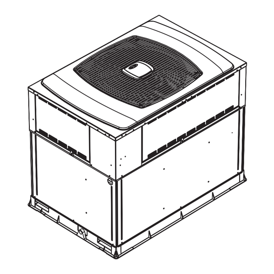
1
Fig. 1 - - Unit 50XT
. . . . . . . . . . . . . . . . . . . . . . . . . . . . . . .
. . . . . . . . . . . . . . . . . . . . . . . . . . . . .
. . . . . . . . . . . . . . . . . . . . . . . . . . . . . . . . . . . .
. . . . . . . . . . . . . . . . . . . . . .
. . . . . . . . . . . . . . . . . . . . . . . . . . . . . . . .
. . . . . . . . . . . . . . . . . . . . . . . . . . . . . . . . . .
®
Piston
. . . . . . . . . . . . . . . . . . . . . . . . . . . . . . . .
. . . . . . . . . . . . . . . . . . . . . . . . . . .
. . . . . . . . . . . . . . . . . . . . . . . . . . .
®
Refrigerant)
. . . . . . . . . . . . . . . . . . . . . . . . . . . . . . .
. . . . . . . . . . . . . . . . . . . . . . . . . . . . . . . . . . .
. . . . . . . . . . . . . . . . . . . . . . . . . . . . . . . .
. . . . . . . . . . . . . . . . . . . . . . . . .
. . . . . . . . . . . . . .
. . . . . . . . . . . . . . . . . . . . . . . . . . . . .
. . . . . . . . . . . . . . . . . . . . . . . . . . . . . . . . . .
. . . . . . . . . . . . . . . . . . . . . . .
. . . . . . . . . . . . . . . . . . . . . . . . . . .
A05307
21- -24
22
22
. . . .
22
22
22
22
22
. . . . . . . . . .
23
23
23
23
. . . . . . .
23
23
23
23
. . .
23
23
23
24
25
25
29
Advertisement

Related Manuals for Carrier Infinity 50XT


Summary of Contents for Carrier Infinity 50XT
- Page 1 50XT Infinityt 15 Packaged Electric Heat Pump System ® With Puron (R- -410A) Refrigerant 2 to 5 Nominal Tons (Sizes 024- -060) Installation Instructions IMPORTANT: OAT sensor must be field installed. See Accessory Installation for more details. IMPORTANT: This Infinityt unit is designed for use with an Infinity User Interface.
- Page 2 Check all items as cleaning and replacing air filters. All other operations must be against shipping list. Immediately notify the nearest Carrier office performed by trained service personnel. When working on this if any item is missing.
- Page 3 HVAC unit HVAC unit base base Gask eting inner flange* Scre w Scre w Gask eting (NO TE A) (NO TE A) inner flange* *Gask eting *Gask eting outer flange outer flange Wood nailer* Wood nailer* Flashing field Flashing field supplied supplied Roof curb*...
- Page 6 Step 3—Provide Clearances This bracket is to be used to rig/lift a Small Packaged Product onto roofs or other elevated structures. The required minimum service clearances are shown in Fig. 5 and 6. Adequate ventilation and outdoor air must be provided. The WARNING outdoor fan draws air through the outdoor coil and discharges it through the top fan grille.
- Page 7 DETAIL A06298 RIGGING MODEL CABINET WT (LB) 50XT- -024 Small Small 50XT- -030 50XT- -036 50XT- -042 Large Large 50XT- -048 50XT- -060 A06296 Fig. 7 - - Suggested Rigging Step 5—Select and Install Ductwork When designing and installing ductwork, consider the following: The design and installation of the duct system must be in accordance 1.
- Page 8 5. Secure all ducts to building structure. Flash, weatherproof, HIGH- -VOLTAGE CONNECTIONS and vibration- -isolate duct openings in wall or roof The unit must have a separate electrical service with a according to good construction practices. field- -supplied, waterproof disconnect switch mounted at, or within CONVERTING HORIZONTAL DISCHARGE UNITS TO sight from, the unit.
- Page 9 Table 1—Physical Data - - Unit 50XT UNIT SIZE NOMINAL CAPACITY (ton) 2--1/2 3--1/2 OPERATING WEIGHT (lb.) COMPRESSOR Two--Stage Scroll REFRIGERANT (R- -410A) Quantity (lb.) 10.3 11.5 14.0 15.5 16.0 EXPANSION DEVICE- -HEATING AccuRater ORIFICE OD (in.) -- Left 0.042 0.038 0.035 0.040...
- Page 10 ROUTING POWER LEADS INTO UNIT C. Humidifier Connections Use only copper wire between disconnect and unit. The high The fan coil control board terminal marked HUM is provided for voltage leads should be in a conduit until they enter the duct panel; low voltage (24- -vac) control of a humidifier.
- Page 11 User Infinity Fan Coil Infinity HP/AC Interface Board Board Outdoor Air Thermistor (Supplied with UI) FIELD CONNECTION REQUIRED (BLACK WIRES) Outdoor Coil Thermistor HUMIDIFIE R FACTORY CONNECTE D (24 VAC) FACTORY WIRES PROV IDED FOR FIELD CONNE CTION OF UTILITY CURTA ILME NT LEGEND Factory Wiring Field Wiring...
- Page 12 PRE- -START- -UP high- -side Schrader fitting located on the compressor discharge line. Be sure that caps on the ports are tight. WARNING START- -UP Step 1—Unit Start- -Up FIRE, EXPLOSION, ELECTRICAL SHOCK HAZARD NOTE: Always check high- - and low- -voltage supply to the unit Failure to follow this warning could result in personal injury components.
- Page 13 If COMM LED does not light within proper time period and status two motor leads should be similar and resistance between code is displayed, any motor lead and unpainted motor end should exceed 100,000 ohms. 1. Check system wiring to be sure UI is powered and connections are made A to A, B to B, etc.
- Page 14 A06280 Fig. 16 - - Wiring Schematic- -50XT Single Phase...
- Page 15 MOTOR TURNS SLOWLY When the motor is commanded to stop, the MOTOR LED will be turned off. The MOTOR LED will not flash to indicate 1. Low static pressure loading of blower while access panel is communications when it is turned off. removed will cause blower to run slowly.
- Page 16 4. Make sure heater size installed is an approved size for unit Shorting or mis- -wiring the low voltage system wiring will not cause and size installed. damage to unit control or to UI but may cause the low voltage fuse to open.
- Page 17 Table 3—HEAT PUMP/AIR CONDITIONER BOARD STATUS CODES AMBER FAULT POSSIBLE CAUSE AND ACTION OPERATION FLASH CODE Standby – no call for unit opera- On solid, None Normal operation. tion no flash Rapid, con- Unit being controlled by standard thermostat inputs instead of Infin- Standard Ther- Emergency Mode tinuous...
- Page 18 (See Fig. 13, 15 and 16). This input allows a power utility device In low stage, fan is off when outdoor coil temp is <outdoor air to interrupt compressor operation during peak load periods. temperature +1_F or outdoor fan has been ON for 30 minutes. When the utility sends a signal to shut the system down, the UI (Fan is turned off to allow refrigerant system to stabilize.) will display “Curtailment Active”.
- Page 19 QUIET SHIFT condition exists somewhere in the cooling system, such as insufficient airflow across either coil or both coils. Quiet Shift is a field- -selectable defrost mode which may eliminate occasional noise that could be heard at the start of the REFRIGERANT CHARGE defrost cycle and restarting of the heating cycle.
- Page 20 A06297 Fig. 17 - - Non- -Communicating Emergency Cooling/Heating Wiring Connections Required Subcooling Required Liquid Line Temperature for a Specific Subcooling (R-410A) Outdoor Ambient Temperature Required Subcooling ( Required Subcooling ( Pressure Pressure (psig) (kPa) Model Size 75 (24) 82 (28) 85 (29) 95 (35) 105 (41)
- Page 21 Table 4—Wet Coil Pressure Drop (in. wg) STANDARD CFM (SCFM) UNIT UNIT SIZE 1000 1100 1200 1300 1400 1500 1600 1700 1800 1900 2000 2100 0.005 0.007 0.010 0.012 0.015 – – – – – – – – – – –...
- Page 22 3. Inspect blower motor and wheel for cleanliness each cooling 1. Remove 4 screws holding outdoor grille and motor to top season. Clean when necessary. cover. 4. Check electrical connections for tightness and controls for 2. Turn motor/grille assembly upside down on top cover to proper operation each cooling season.
- Page 23 ® Step 8—Metering Devices- -TXV & AccuRater Piston has an operating range between 550 and 625 psi differential pressure. This unit uses 2 types of metering devices. The outdoor metering The Copeland scroll compressor uses Mobil 3MA POE oil. This device is a fixed orifice and is contained in the brass- -hex body in the liquid line feeding the outdoor coils.
- Page 24 refrigerant to flow from cylinder in upright position. For 8. In the event of a low- -pressure switch trip or low pressure cylinders equipped with a dip tube, charge Puron units with cylinder lockout, check the refrigerant charge and indoor airflow. in upright position and a commercial metering device in manifold CONTROL FAULT hose.
- Page 25 COMPRESSOR INTERNAL RELIEF If the OAT sensor should fail, low ambient cooling will not be allowed and the one- -minute outdoor fan off delay will not occur. The compressor is protected by an internal pressure relief (IPR) Defrost will be initiated based on coil temperature and time. which relieves discharge gas into compressor shell when differential between suction and discharge pressures exceeds 550 If the OCT sensor should fail, low ambient cooling will not be...
- Page 26 HEAT PUMP WITH PURON REFRIGERATION SECTION QUICK- -REFERENCE GUIDE Puron refrigerant operates at 50- -70 percent higher pressures than R- -22. Be sure that servicing equipment and replacement components are designed to operate with Puron. Puron refrigerant cylinders are rose colored. Puron refrigerant cylinders manufactured prior to March 1, 1999, have a dip tube that allows liquid to flow out of cylinder in upright position.
- Page 27 Table 8—Troubleshooting Chart SYMPTOM CAUSE REMEDY Power failure Call power company Fuse blown or circuit breaker tripped Replace fuse or reset circuit breaker Defective contactor, transformer, HP/AC control board, Defective contactor, transformer, HP/AC control board, Replace component or high--pressure, loss--of--charge or low--pressure or high pressure, loss of charge or low pressure switch Insufficient line voltage...
- Page 28 Table 8—Troubleshooting Chart (Cont’d) SYMPTOM CAUSE REMEDY Low refrigerant charge Check for leaks, repair and recharge Head pressure too low Head pressure too low Restriction in liquid tube Remove restriction (Cool) High Heat load Check for source and eliminate Excessive suction pressure Excessive suction pressure Reversing valve hung up or leaking internally Replace valve...
- Page 30 *Measured at suction inlet to compressor †Measured at liquid line leaving condenser. A05306 Catalog No: 50XT- - 1SI Copyright 2006 Carrier Corp. S 7310 W. Morris St. S Indianapolis, IN 46231 Printed in U.S.A. Edition Date: 11/06 Replaces: New Manufacturer reserves the right to change, at any time, specifications and designs without notice and without obligations.
Need help?
Do you have a question about the Infinity 50XT and is the answer not in the manual?
Questions and answers