SIRUI K-X Series, K-10X, K-20X, K-30X, K-40X - Ball Head Manual
- Instructions (2 pages)
Advertisement
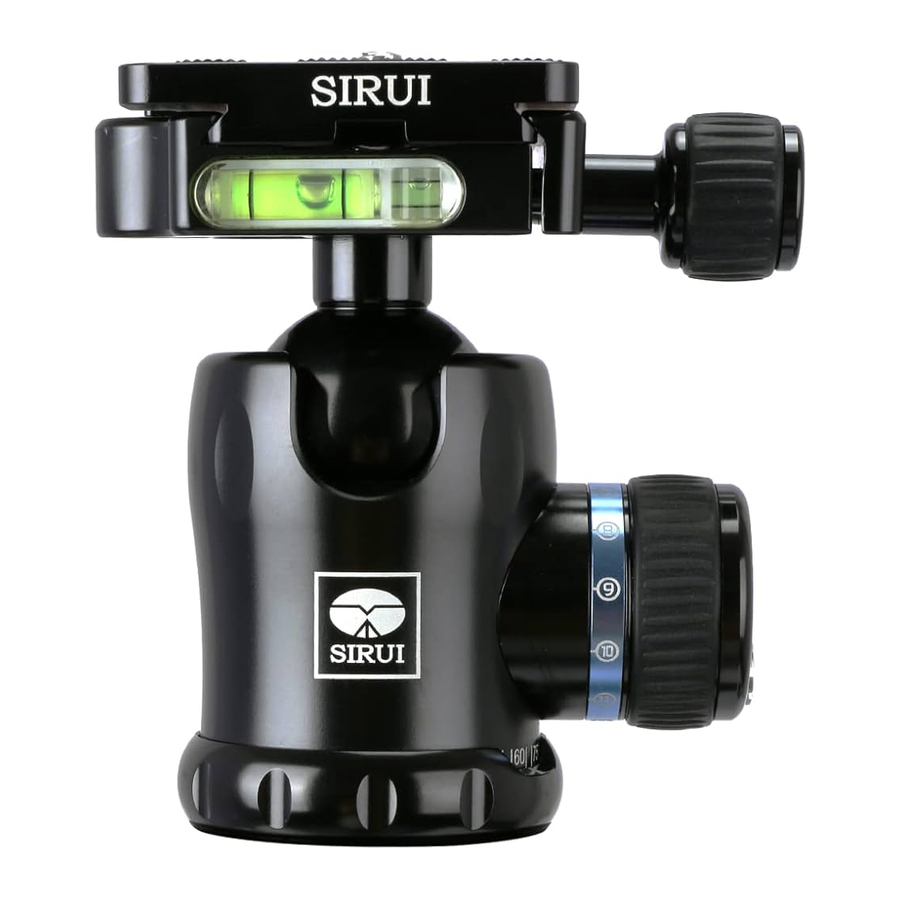
Know Your Ball Head
K-X Series:

Attaching Your Ball Head
- To attach the ball head onto the tripod, you must make sure that the mounting screw of your tripod is 3/8". If it is 1/4" you will need to get a 3/8" screw or adapter. Many professional tripods have reversible screws. Please check your tripod manual for more details.
- Lock the Panning Base Locking Knob by turning it in a clockwise direction. As shown on Figure 2-1 & 2-2, align the 3/8" thread hole at the bottom of the Ball Head with the mounting screw on the tripod. Hold by the base of the Ball Head and rotate in a clockwise direction until it is locked tightly.


Know your Quick Release Clamp and Quick Release Plate

Attaching and Removing the Quick Release Plate
Attaching the QR Plate to Your Camera
Select the QR Plate that matches the base of your camera. (To prevent excessive wear to the camera's tripod socket, you should not frequently attach and remove the Quick Release Plate. It is quite common to leave the QR Plate permanently attached to the camera.) The side of the Quick Release Plate with the slide-proof rubber mat must be facing the base of the camera. Make sure the QR Plate screw aligns with the tripod socket on the bottom of the camera. Position the QR plate on the camera body and tighten the screw with a coin or allen key. If you plan to keep the quick release plate on your camera for a long period of time or you are using medium or large format cameras, you should tighten the screw with the allen key.
Attaching the camera with QR Plate onto the Ball Head
Slightly loosen the Clamp Locking Knob by turning it counter-clockwise, slide the QR plate laterally into the Quick Release Clamp (Figure 4-1)

and tighten the clamp by turning clockwise. Another method is to fully open the Clamp Locking Knob and place the plate in from the top (Figure 4- 2). Tighten the knob to lock the camera in place.

Figure 4- 2
Security Pin on the Quick Release Clamp
There is a safety lock on the top of the Quick Release Clamp that effectively prevents the camera from sliding off of the clamp if it is slightly loosened (Figure 4-3).

This allows you to make minor adjustments of the camera position on the Ball Head without worrying about the camera sliding off of the Quick Release Clamp. This feature is available with all Sirui QR plates.
(
While other styles of QR plates can be used on Sirui Ball Heads, this safety feature may not be available with other brands of QR plates. Even with the Sirui QR Plates, you should hold your camera while loosening the Quick Release Clamp).
Removing the Camera with QR Plate from the Ball Head
While holding the camera, loosen the Clamp Locking Knob by slightly turning it counter-clock-wise. Push in the Security Pin Release Button and slide the camera off of the Clamp Plate (Figure 4-4).

You can also remove the camera by fully opening the clamp and lifting the camera out of the clamp.
Camera Screw Usage
The 1/4" screw with buckle can only be used in the middle slot of the QR Plate. The standard 1/4" screw can be used in the left or right slot, if the position of your camera's 1/4" tripod socket is off-center, as shown in Figure 3-2.

Factory Setting
- As shown in Figure 5-1, turn the Main Locking Knob in a clockwise direction about 1/2 turn. Next, turn the Friction Adjustment Dial in a counter-clockwise direction until it stops. Loosen the Main Locking Knob by turning in a counter-clockwise direction until it stops.
![]()
- As shown in Figure 5-2, while slowly rocking the camera, turn the Main Locking Knob clockwise until you feel the resistance you desire.
![]()
Then turn the Friction Adjustment Dial clockwise until it stops (Figure 5-3).
![]()
- Turn the blue Calibration Ring (around the Main Locking Knob) to the O position (Figure 5-4).
![]()


Basic Operation

Adjusting the Ball Head
Mount your camera onto the Ball Head. While holding the camera, loosen the Main Locking Knob (Figure 7-1).

The ball head will be very loose, so you will need to adjust the amount of resistance you prefer. Rotate the Friction Adjustment Knob that is in the Main Locking Knob in a counter-clockwise position until it stops. While slowly rocking the camera, tighten the Main Locking Knob until you feel the resistance you desire. The friction adjustment should be set so that there is enough resistance to prevent the camera from easily tipping over, while giving you the ability to make adjustments to camera position without having to use excessive force. This becomes very useful when using telephoto lenses and when critical alignments need to be made. When the resistance level you want is achieved, stop turning the Main Locking Knob. Turn the Friction Adjustment Knob in a clockwise position until it stops (Figure 7-2).

Figure 7-2
You may want to start shooting immediately or you can tighten the Main Locking Knob to firmly lock the head in place. Before locking the Ball Head, you may want to use the bubble levels to make sure it will be horizontal.
UnIocking the Ball Head
You may find that the Ball Head is locked in position (usually from excessive force) and needs to be released. Please follow the below instructions, paying attention to the turning directions.
If possible, mount the Ball Head on the tripod and turn the Main Locking Knob in a clockwise direction (Figure 8-1)

Figure 8-1
Turn the Friction Adjustment Dial in a counter-clockwise direction until it stops (Figure 8-2).

Figure 8-2
 Note: the Quick Release plate has a strap holder that allows you to attach many popular camera straps directly onto the plate. Please make sure that the Quick Release plate is securely attached to the camera, to prevent the possibility of the camera detaching from the plate. Please check this attachment regularly.
Announcements
 Do not exceed the recommended load limit of the ball head and/or tripod. (Please refer to product specifications.)
Please make sure that the locks are securely tightened when in use.
 This product should not be used in environments that exceed the following conditions (-40 —+1000C/-40 —212OF).
 When used in damp, dirty or dusty environments, please clean and dry thoroughly after use, to assure proper functioning in the future.
 Please keep from high temperatures and direct exposure to bright sunlight for extended periods of time.
 To protect your camera gear, please remove it from the tripod/ball head when transporting from place to place.
 Prevent sand, grit and other foreign matter from getting into the interior of the Ball Head. If the Ball Head does not move smoothly, please use a clean, soft cloth to gently wipe the Ball mechanism.
 There is no need to lubricate any parts Of this product. The addition Of lubricants will gum up the mechanisms and i reduce their normal gliding characteristics. The construction of Sirui professional Ball Heads is very precise, so extra maintenance is not needed.
 Please keep this product away from all electrical power sources.
Specifications are subject to change without notice.
Documents / ResourcesDownload manual
Here you can download full pdf version of manual, it may contain additional safety instructions, warranty information, FCC rules, etc.
Download SIRUI K-X Series, K-10X, K-20X, K-30X, K-40X - Ball Head Manual
Advertisement


Need help?
Do you have a question about the K-X Series and is the answer not in the manual?
Questions and answers