Table of Contents
Advertisement
Quick Links
USB-IRIS-W10
Evaluation kit for IRIS-W1 series modules
User guide
Abstract
The document describes how to set up USB-IRIS-W106 evaluation kits for prototyping
USB-IRIS-W106 series modules. It provides setup instructions for starting development and
describes the hardware functionality of USB-IRIS-W106 evaluation kit.
UBX-23005189 - R02
C1-Public
www.u-blox.com
Advertisement
Table of Contents

Related Manuals for Ublox USB-IRIS-W106


Summary of Contents for Ublox USB-IRIS-W106
- Page 1 Evaluation kit for IRIS-W1 series modules User guide Abstract The document describes how to set up USB-IRIS-W106 evaluation kits for prototyping USB-IRIS-W106 series modules. It provides setup instructions for starting development and describes the hardware functionality of USB-IRIS-W106 evaluation kit.
-
Page 2: Document Information
Document contains the final product specification. End of life This document applies to the following products: Document status Product name USB-IRIS-W106 Early production information ☞ For information about the hardware, software, and status of the available product types, see the IRIS-W10 data sheet [1]. -
Page 3: Table Of Contents
USB-IRIS-W10 - User guide Contents Document information ..........................2 Contents ................................3 Product description ..........................4 1.1 Overview ................................ 4 1.2 Kit includes ..............................4 1.3 Key features ..............................4 Setting up the evaluation board ....................... 5 2.1 Prerequisites ..............................5 2.2 Starting up the EVB ............................ -
Page 4: Product Description
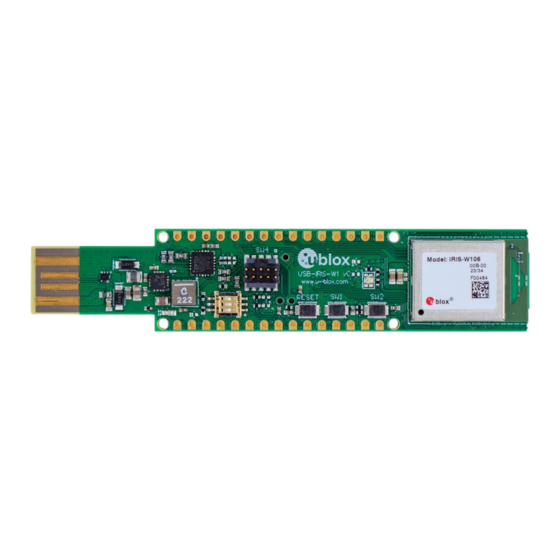
Product description 1.1 Overview The USB-IRIS-W106 evaluation kit provides stand-alone use of the IRIS-W106 series module. The most essential features of IRIS-W106 series modules are easily accessed from the USB Type-A evaluation board (EVB). A simple USB connection provides power, programming, and COM ports. Two user buttons, RESET and a BOOT are available, as well user LEDs. -
Page 5: Setting Up The Evaluation Board
Automatic Bootloader/Strap-in Interface pin-out. 2.2 Starting up the EVB Connect the USB-IRIS-W106 stick to the PC to power up the module. • The green status LED (LD1) should be lit to indicate that the internal EVK 3V3 supply is active. •... - Page 6 USB-IRIS-W10 - User guide To run application, open a UART console (Putty, TeraTerm, or another terminal emulator), Wi-Fi_CLI and set the serial port to 115200 baud rate, 8-bit data, No parity, 1-bit stop, No flow and run various feature sets offered by application as shown in Figure Wi-Fi_CLI...
-
Page 7: Software Development
USB-IRIS-W10 - User guide Configure device B as Station with iperf client To configure device B as a Station with iperf server, open a terminal session and enter: wlan-add test1 ssid NXPAP ip:192.168.10.3,192.168.10.1,255.255.255.0 channel 48 wpa2 psk 12345678 wlan-connect test1 iperf -c 192.168.10.1 ☞... -
Page 8: Hardware Description
USB-IRIS-W10 - User guide Hardware description ☞ Design files for the USB-IRIS-W106 are available in the u-blox short range EVK designs GitHub repository [3]. Figure 2 shows the major components and their location on USB-IRIS-W10. Figure 2: Major components on USB-IRIS-W10... - Page 9 USB-IRIS-W10 - User guide Table 1 describes the pin assignments for the needle connector, J3. Pin name IRIS-W10 pin Function +3V3 Supply JTAG-TMS Ground JTAG-TCK No connection JTAG-TDO No connection JTAG-TDI No connection JTAG-nTRST Module reset Table 1: Needle connector J3 Table 2 describes the pin assignments for the Arduino Nano interface, J5.
-
Page 10: Power
The EVB can be powered through the options described in Power. When inserted in the USB host or supplied through the VIN NANO interface, the input voltage VBUS (5 V) powers USB-IRIS-W106 EVK. The EVB is populated with a fixed 3.3 V, 3 A step-down converter (TPS62132RGTR), as shown in Figure 4. -
Page 11: Com And Debug Ports
USB-IRIS-W10 - User guide Figure 5 shows the IOREF separation circuit in the USB schematic. By default, resistor R51 is not populated. ☞ The VIO supply to the module on USB-IRIS-W1 is hardwired to +3V3 and can’t be changed. Figure 5: USB schematic - IOREF separation •... -
Page 12: Reset
USB-IRIS-W10 - User guide 3.3 Reset USB-IRIS-W106 supports a hardware reset to the IRIS-W106 module. The Reset button is connected to the module PDn pin. Figure 7: Reset button 3.4 LEDs The green power LED (D1) is lit to indicate that the board is powered on. -
Page 13: Serial Communication
USB-IRIS-W10 - User guide 3.5 Serial communication The evaluation board allows for easy serial communication with the IRIS-W10 module and a connected computer. By default, the USB uses a single FTDI interface IC (U2) that accommodates one COM port. ☞ The single port is connected to module through 1kΩ... -
Page 14: Debug Interfaces
USB-IRIS-W10 - User guide Figure 10 shows the connections and signal state table describing the configuration inputs required to set the boot mode following a reset. The definition of these pins reverts immediately to their usual function after reset. Figure 10: Boot strap connection and signal states 3.7 Debug interfaces There are two interfaces for debugging and programming IRIS-W10: SWD and JTAG. -
Page 15: Jtag
USB-IRIS-W10 - User guide 3.7.2 JTAG The evaluation board supports a standard JTAG connector and a JTAG needle connector, which serve the same fundamental purpose of providing a connection for Joint Test Action Group (JTAG) interfaces. Standard JTAG interface The standard JTAG debug interface is shown in Figure 12. -
Page 16: Qspi Sram
USB-IRIS-W10 - User guide 3.8 QSPI SRAM USB-IRIS-W106 provides an option to extend external memory with a Quad SPI SRAM (U3), which can be optionally mounted on the bottom-side of the evaluation board, as shown in Figure Figure 14: QSPI memory Table 6 describes the pin assignment and interface functions of each QSPI memory signals. -
Page 17: Appendix
USB-IRIS-W10 - User guide Appendix A Re-load Wi-Fi_CLI example A.1 Prerequisite Download the J-Link software (V7.98i and above) from SEGGER [5]. Using external debugger connected to J4 connector, as described in Debug interfaces, flash the IRIS-W1 module with a pre-compiled Wi-Fi_CLI application. Identify the IRIS-W10 integrated flash memory type as described in the NXP MCUXpresso SDK,... - Page 18 USB-IRIS-W10 - User guide 4. Flash the wifi_cli application rw612_wifi_cli_v16_fi8.hex. Figure 17: Flashing Wi-Fi_CLI application UBX-23005189 - R02 Appendix Page 18 of 20 C1-Public...
-
Page 19: B Glossary
USB-IRIS-W10 - User guide B Glossary Abbreviation Definition Arm (Advanced RISC Machines) Holdings Central Processing Unit Clear To Send Direct Current DC-DC DC to DC converter Device Firmware Update Evaluation Kit FICR Factory Information Configuration Register GPIO General Purpose Input / Output Low Drop-Out voltage regulator Low Energy Light Emitting Diode... -
Page 20: Related Documentation
USB-IRIS-W10 - User guide Related documentation IRIS-W10 data sheet, UBX-23002331 IRIS-W10 system integration manual, UBX-23003263 EVK design Github repository, evk_designs_sho_altium Blhost.exe User’s guide https://www.nxp.com/docs/en/user-guide/MCUBLHOSTUG.pdf SEGGER J-Link software Open CPU Github repository u-blox-sho-OpenCPU EVK-IRIS-W1 user guide, UBX-23007837 MCUXpresso Software Development Kit ☞...
Need help?
Do you have a question about the USB-IRIS-W106 and is the answer not in the manual?
Questions and answers