Table of Contents
Advertisement
Quick Links
Advertisement
Table of Contents

Related Manuals for Riding'Times GT53


Summary of Contents for Riding'Times GT53
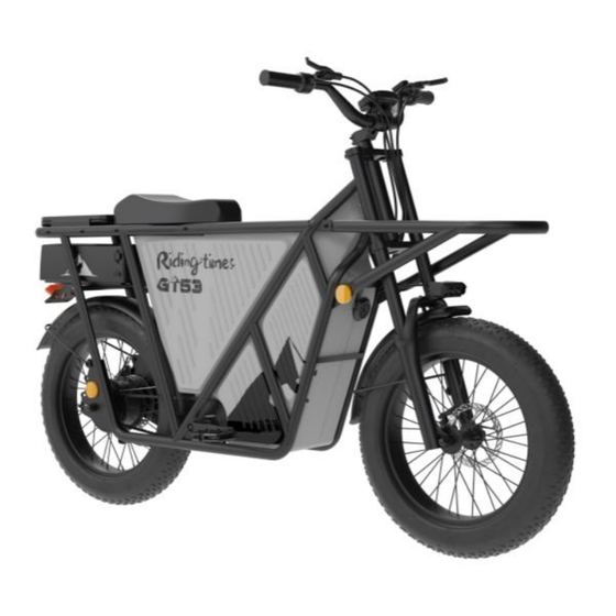
- Page 1 Original Instructions User's Manual GT53 electric bike...
- Page 2 Welcome 1. Join the Riding'times community of riders wherever you are! This is just the beginning of your adventure with us! We look forward to hearing about your experience and seeing you online on our social networks: Facebook Group Name: Riding'times Global Group Group Link: https://www.facebook.com/groups/1331441984237849...
- Page 3 5.Customer Service EN:Our product technology is already very mature, with 20 years of trade, we have distributors all over the world who can provide you with the most localized and professional technical support within 24 hours. DE:Unsere Produkttechnologie ist sehr ausgereift, mit 20 Jahren Handel haben wir weltweit Vertreter, die Ihnen innerhalb von 24 Stunden die bestmögliche lokalisierte und professionelle technische Unterstützung bieten.
- Page 4 -Reorient or relocate the receiving antenna. -Increase the separation between the equipment and receiver. -Connect the equipment into an outlet on a circuit different from that to which the receiver is connected.Consult the dealer or an experienced radio/TY technician for help. This equipment complies with FCC radiation exposure limits set forth for an uncontrolled environment.
- Page 5 Bike frames and parts have limitations, and extreme riding should not be performed. GT53 assumes no liability for any accident, injuries,or property damage incurred as a result of rider’s use or misuse of GT53 bicycles, including any damages resulting from or arising out of off-road usage.
- Page 6 • Proper installation, compatibility, operation, and maintenance must be performed on all components. Failure to comply could result in serious injury or death. When installing the battery, any water or ice on the battery connector can cause the battery to burn out. The key is used to remove the battery, inserting the key into the charging port can also cause the battery to burn out.Avoid touching the two metal contacts of the battery box at the same time, as it may generate a large short-circuit current and lead to an accident.Any aftermarket changes or modifications to your bike could void the warranty and...
- Page 7 Sticker Area...
-
Page 8: Table Of Contents
Contents 1. Components Diagram --------------------------------------------------------------7 2. Assemble Electric Bike ------------------------------------------------------------- 8 3. Technical Parameters -------------------------------------------------------------- 15 4. Battery Instructions ---------------------------------------------------------------- 17 5. Instructions of the Dashboard ----------------------------------18 Loading Instructions -------------------------------------------23 7. Considerations ----------------------------------------------------------------------- 24 8. Maintenance and Cleaning ------------------------------------------------------- 24 9.Oil brake maintenance ----------------------------------------- 10. -
Page 9: Components Diagram
1. Components Diagram... -
Page 10: Assemble Electric Bike
2. Assemble Electric Bike 2.1.Take out of the electric bike from the box(Figure 2-1-1)。 Figure 2-1-1... - Page 11 2.2.Assemble the handlebar: Put the handlebar into the center of the vertical bar, fasten the screws by using NO.4 Allen Wrench(Figure 2-1-2)。 Figure 2-1-2 2.3.Assemble the front wheel: Place the front wheel on the suspension fork with the disc brake on the left side of the e-bike.
- Page 12 2.4.Install the shelves:Take out the front shelf, M6 screws and nuts, left and right reflectors from the accessory box, and assemble them with the frame connection position using a No. 5 Allen wrench and a No. 10 open-end wrench. Note: The reflectors are installed in the lower holes. Figure 2-1-4 2.5.Open and reset the seat, loosen the first two screws to open it.
- Page 13 2.6.Install the battery: First rotate the key to the open position, align it with the slide rail groove and install it into the frame (note: install the battery box into the 2/3 position of the frame, insert the power head into the output port, and finally push the battery to align with the track) key hole, turn the key to the closed state), and the battery box assembly is completed (Figure 2-1-6).
- Page 14 2.8.Assemble the pedal plate: Take out of the left and right pedal plate, “L “is for left side and “R” is for the right side(Figure 2-1-8),, put the pedal plate on the crank, fasten it by using the open spanner 2-1-9).
- Page 15 2.10Schematic diagram of display circuit docking (Note: the corresponding limit of each waterproof head cannot be installed incorrectly to avoid hardware damage)Figure 2-1-11. Figure 2-1-11...
- Page 16 2.11Manage the cable harness: Take out of the winding tube from the accessory box, tie the left and right wire harnesses together(Figure 2-1-12)。 Figure 2-1-12 2.12Connect the headlight waterproof head, align the direction, install it in place and tighten the rubber nut (Figure 2-1-13) Figure 2-1-13...
-
Page 17: Technical Parameters
3.Product Parameters/Features 3.1Product Parameters GT53 electric bike sheet Model GT53 Product name electric bike Configuration NFC card none battery model 48V 22.9AH Battery weight About 7.2KG Motor Motor*1 charger 54.6V/2A*1 Single charger 10-12H/double charger Charging time 5-6H display Digital display instrument LED... - Page 18 3.2.Product Features 3.2.1. Speed mode: 3.2.2.Pure assist mode: factory default 25KM/H. 3.2.3. Throttle and assist coexistence mode: ECO gear 25KM/H, STD gear 35KM/H, TURBO gear 50KM/H. 3.2.4. Braking method: power-off braking. 3.2.5. Tail light: The light is always on when turned on, and highlighted when the brake is applied. 3.2.6.
-
Page 19: Battery Instructions
4.Battery Instructions 4.1Battery charging This bicycle is an external lithium battery, which can be removed for charging. When the battery is low, open the key and take out the battery. Hold the battery tightly with both hands to prevent it from falling, Take out the charger, plug the input end into the power supply,Insert the M16 aviation head of the output terminal into the battery charging hole. -
Page 20: Instructions Of The Dashboard
5.Instructions of Dashboard 5.1.Specifications 48V power supply Rated working current 15mA Maximum working current 30mA Leakage current at power-off<1uA Working current at the supply controller end 50mA Working temperature- 2 0 ~ 6 0 ℃ Storage temperature-3 0 ~ 7 0 ℃ 5.2.Appearance and dimensions(Model BM06) 5.3.Button appearance picture(Model K2) - Page 21 5.4.Display/Press Function overview and functional area layout 5.4.1Display Function overview and functional area layout 1.NFC 2.Headlight 3.Cruise control 4.Power 5.Single mileage 6.Speed 7.Range 8.Max speed 9.Energy saving mode 10.Nomal 11.Sport mode 12.Push mode 5.4.2Button Function overview and functional area layout 13.Headlight switch 14.Function 15.Tum on/off...
- Page 22 5.5.General operation 1. Turn on and off: Press and hold the power button for 2 seconds to turn on/off (Figure 5-1), put the NFC card on the interface (Figure 5-1), unlock it after hearing the beeping sound, and after unlocking, the display (Figure 5-2) will enter the normal mode.
- Page 23 4.2. Function menu switching: In the setting interface state, Press to increase the menu options upward; Press to decrease the menu options downward; 4.3. Function menu parameter switching: In the function menu interface state, Press the "S" key to increase the parameters upward;...
- Page 24 P04: Brightness adjustment. 1 darkest; 2 normal; 3 brightest; default 3 (Figure 5-10) 5-10 P05: Sleep time setting: 1-60 minutes; default 10 minutes (Figure 5-11) 5-11 P06: Clear total mileage: Long press the "S" key (Figure 5-12) 5-11 P07: Add 2 NFC secondary cards (Figure 5-12), put the card on the display, hear a beep, 0 changes to 1, indicating the addition is successful (Figure 5-13).
-
Page 25: Loading Instructions
6. Loading instructions 6.1. The maximum weight of this product is 10KG for the front and rear shelves, and 140KG for the middle cargo bay + person. 6.2.For the sake of riding safety, please do not overload the vehicle. -
Page 26: Considerations
7.Considerations Please use it safely, and do not plug or unplug the display when it is powered on. · Please avoid bumping as far as possible. · Please do not alter the background parameter settings of the display at will otherwise normal riding cannot be guaranteed ·... -
Page 27: Oil Brake Maintenance
8.Oil brake maintenance 8.1. Please read the manual before maintenance and do not leave it to inexperienced personnel. 8.2. The upper and lower pumps of this product produce braking function by extrusion through the oil pipe output. The internal oil should be maintained after 10 months under normal use (except for other improper use) to avoid air generated inside the brake pump causing braking. - Page 28 7. Insert the short hose into the oil filling barrel, connect the hose and the oil cylinder with the M4 oil filling nozzle connector, and then tighten the screws by hand. 8. Use another oil filling cylinder to extract 20ml of new engine oil 9.
- Page 29 12. During the last pump, a little oil is left in the oil filling barrel. 13. Replace the oil filling cylinder with the exhaust gas cylinder. When pulling out the oil filling barrel, wrap it with a cloth to prevent oil from overflowing. 14.
- Page 30 18. Bleed the air from this end of the handbrake lever and extract the air from the tube 19. Repeat extraction several times until no bubbles or very few bubbles are visible in the tube. 20. After the last injection, loosen the interface and tighten the oil seal screw. 21.
-
Page 31: Troubleshooting Instructions
10.Troubleshooting Instructions Display error code Fault name Fault name Fault code Fault code Brake failure Throttle Handle failure Lack voltage protection Controller failure Motor Hall failure Controller/Display communication failure 11.Warranty (1). Warranty information For the faults caused by the quality of the product under normal use, the company will be responsible for ·...
Need help?
Do you have a question about the GT53 and is the answer not in the manual?
Questions and answers
when GT53 stops it atomatically goes into park in 30 seconds, can this be stopped? This is a huge problem, why would it do this?
The Riding'Times GT53 electric bike has an automatic parking feature where the display enters the "P" position after 30 seconds of inactivity. This can be released by holding the brake and clicking the on/off button. Therefore, while it cannot be permanently disabled, it can be manually exited when needed.
This answer is automatically generated
What’s mode 8?
Can l chat?