Advertisement
Quick Links
*941109-00*
941109-00
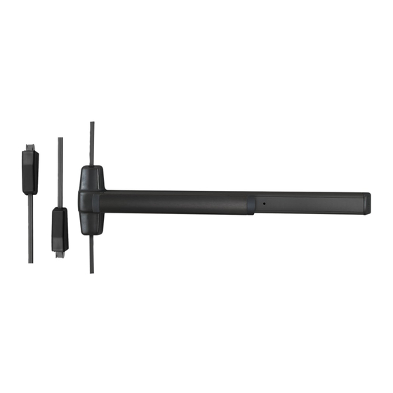
Windstorm Exit Device
WS9827/WS9927 & WS9827-F/WS9927-F
WS-T9827/WS-T9927 &
WS-T9827-F/WS-T9927-F
!
You must use the screws and sexbolts provided with this exit
device or the device will not be Tornado or Windstorm
certified. Do not substitute any hardware on door.
1
Draw Exit Device Centerline ( )
39-1/2" (100 cm) from finished floor
RHR
Customer Service
1-877-671-7011
!
NOT PERMITTED FOR WS-T APPLICATIONS
Cylinder Dogging with Thumb-turn Acceptable
For WS applications, a dogging key can be used to
lock down pushbar.
For WS-T applications, a cylinder dog with
thumbturn can be used to lock down pushbar.
A dogging key is not permitted.
WS-T Information
If using -2 or -2SI options, 377T-KC function required.
See instruction #47640278 for -2 & -2SI information.
See instruction #941116-00 for 377T-KC trim installation and door preparation.
Rod Guide and Spacer Information
For WS applications, use 1 rod guide centered above and
below the exit device. No spacers are required.
For WS-T applications, use 3 rod guides per rod. Also use a
spacer plate under top latch and under rod guides nearest the
exit device. See exploded view to the left.
RHR
LHR
www.allegion.com/us
Installation Instructions
#10-24
#12-24
Dogging Key
2
Assemble Plastic Template
941109-00 Rev. 04/24-H
©Allegion 2024
Printed in U.S.A.
Advertisement

Related Manuals for Von Duprin WS9827


Summary of Contents for Von Duprin WS9827
- Page 1 WS9827/WS9927 & WS9827-F/WS9927-F *941109-00* WS-T9827/WS-T9927 & 941109-00 WS-T9827-F/WS-T9927-F Windstorm Exit Device Installation Instructions You must use the screws and sexbolts provided with this exit device or the device will not be Tornado or Windstorm certified. Do not substitute any hardware on door.
- Page 2 Mark Door For Top & Bottom Latches Using Paper Affix Template and Mark Vertical Center Line Templates On Back Cover Flush With Soffit Note: If using threshold or floor strike, set prior to marking lower latch holes. See page 5 for bottom strike installation information.
- Page 3 Check to see if two holes have been prepared in the top of the frame. If necessary, drill and tap holes as shown below. Mark and Drill Top Strike Holes Using Soffit as Template Thru-bolting Trim Sex Bolts If Necessary, Cut Device 1¹⁄...
- Page 4 Note: For WS-T applications only, Install the spacer plate under top latch.
- Page 5 Bottom Strike Installation (Refer to Template on Back Page as Needed) Threshold Applications Floor Applications Zero 566A threshold shown with 304L Cup Strike for WS. For other Grout strike into floor as shown. thresholds, see instructions supplied with threshold for specific details.
-
Page 6: Install Rod Extension
Top rod may need to be cut or extended for doors other than 7’ tall CUT TOP ROD 2. Cut rod. 1. Measure amount to cut off rod as shown below. Note: Rod cutting is required for doors shorter than 2134mm’. Amount Drive out to cut off... - Page 7 Adjust Top Rod Prop Door Open Continued Slowly Depress Pushbar (c) Verify That Top Latch Clicks and Holds (d) Place Top Rod in Slot of Top Latch Install Rod Guide(s). See Important Note Below. For WS applications, use 1 rod guide centered below the exit device.
- Page 8 Adjust Bottom Rod Screw Bottom Rod Fitting All the Way In Install Rod Guide(s). See Important Note Below. For WS applications, use 1 rod guide centered below the exit device. No spacers are required. For WS-T applications, use 3 rod guides above and below exit device.
- Page 9 Install Rod Guides WS Application WS-T Application For WS applications, use 1 rod guide centered below the For WS-T applications, use 3 rod guides above and exit device. No spacers are required. below exit device. Also use a spacer plate under the rod guide nearest the exit device.
-
Page 10: Install Covers
Install covers WS Application Shown... - Page 11 This page is intentionally left blank.
- Page 12 FOLD Top Latch Flush with Soffit ⁷⁄ " (22 mm) soffite ¹³⁄ " (21 mm) 3 ¹⁄ " (79 mm) 1¹³⁄ " (46 mm) 1 ⁷⁄ " (36 mm) 1 ³⁄ " (35 mm) 1 ³⁄ " Bottom Bracket (35 mm) 1 ⁷⁄...
Need help?
Do you have a question about the WS9827 and is the answer not in the manual?
Questions and answers