
Related Manuals for StarCharge Jupiter V3


Summary of Contents for StarCharge Jupiter V3
- Page 1 Charging Infrastructure Jupiter V3 Commissioning Manual Wanbang Digital Energy Co. Ltd.
-
Page 2: Legal Statement
Legal Statement Wanbang Digital Energy Co., Ltd. No. 39 Longhui Road, Wujin High-tech Zone, Changzhou, Jiangsu, Chinawww.starcharge.com All rights are reserved by Wanbang Digital Energy Co., Ltd. This document is part of technical file “Charging Infrastructure” and copyrighted. Without any prior written consent, it’s strictly not allowed to use it out of the permission of copyright, which is also applied to copied,... -
Page 3: Table Of Contents
Content General Principle ............................1 Purpose of this Document ........................1 Definition of Warning Sign ........................1 Preparation before Commissioning ......................2 Safety Notice ............................2 Outside Appearance of EVSE ....................... 4 Datasheet ............................. 5 Specification of Power Module ......................6 LED Light Indication .......................... - Page 4 3.5.2 Hardware Function Test ......................... 56 Customer Training ............................. 57 Appendix 1 Customer Training Record Sheet ....................58 Appendix 2 Commissioning Report ........................59...
-
Page 5: General Principle
1.1 Purpose of this Document The purpose of this document is In In order to facilitate the normal successful use of Jupiter V3 after installation. The information supports to discover and eliminate the failure or issues hidden dangers of the charger caused by factors such as installation quality, site conditions or and the environment (such as power voltage). -
Page 6: Preparation Before Commissioning
Preparation before Commissioning 2.1 Safety Notice Warning! Only manufacturer’s engineers or engineers trained by manufacturer are allowed to do commissioning to EVSE. Star Charge will not be responsible for any loss caused by the operation of any third-party engineers without Star Charge’s authorization. Each step of commissioning must be handled carefully. - Page 7 8) Without authorization and approval, any change of connection and structure inside of the EVSE is not allowed. 9) After operating, please put the components back to the original place, count the tools to prevent missing, and clean the operation site. 10) In case of any emergency, please launch the emergency response plan immediately, report the situation to the responsible person according to the plan, and carry out the on-site emergency treatment in the first time to control spreading, and rescue person and property.
-
Page 8: Outside Appearance Of Evse
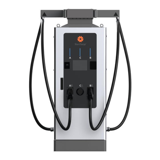
2.2 Outside Appearance of EVSE Ground-mounted Figure 1 Outside Appearance of EVSE [A] ——LED status indicator [B] ——Card swiping area for charging [C] ——Touch screen [D] ——Door lock [E] ——Charging connector slot [F] ——Charging cable management system ... -
Page 9: Datasheet
2.3 Datasheet Product name Jupiter 60kW V3 General parameters Model DC0600EN052-A Rated input 400Vac±10%, 3-Phase, 50/60 Hz, L1+L2+L3+N+PE Power factor 0.99 (Normal load) Total harmonic Input parameters ≤5% (More than half a load) current: ≥94%@full load Efficiency ≥95% at nominal output power Output Interface DC CCS2*2+AC TYPE 2 Output Voltage CCS2:150-1000Vdc... -
Page 10: Specification Of Power Module
2.4 Specification of Power Module Jupiter V3 uses Star Charge 30kW 1000V power module, which has a feature curve as follows: Figure 2 Feature curve Module High-voltage Low-voltage Parameter Value Value Range of output voltage 200~1000V 150~500V Rated output voltage... -
Page 11: Led Light Indication
2.5 LED Light Indication LED Light State Definition Steady green Normal Flashing green RFID card identified Steady yellow There’s some fault which doesn’t affect charging. Steady blue Charging Steady red Fault Flashing red Fail to verify RFID Card Table 3 LED light indication Commissioning Manual Wanbang Digital Energy Co. -
Page 12: Commissioning Tools
2.6 Commissioning Tools Please check and prepare the following tools before commissioning: Item Tools Usage Example Laptop Configure the settings and read logs Ethernet cable Web configuration J – LINK tool Programming 5/6 pin adaptor and flat cable Programming Micro SD Card and reader Programming Screwdriver set Assemble and disassemble the screws... - Page 13 Electrician protective gloves Safety protection Electrician protective Shoes Table 4 Tool list Commissioning Manual Wanbang Digital Energy Co. Ltd...
-
Page 14: Commissioning Process
Commissioning Process 3.1 Commissioning Flowchart The commissioning flowchart of DC EVSE is as follow: Commissioning Flow Chart for DC EVSE Installation Technical Support Commissioning Engineer Engineer Engineer Installation recheck Whether the Corrective installation meets the maintenance requirements Check before power on Whether the appearance, internal wiring, insulation resistance and input... -
Page 15: Installation Recheck
Warning! During the commissioning process, the engineer cannot leave when the cabinet is opened and must remind any other people of staying far away. Make sure that all doors of the cabinet are closed when leaving the commissioning site. 3.2 Installation Recheck Commissioning must be operated by the engineers qualified by local special operation regulations. -
Page 16: Insulation Resistance Check Of Input Power Cable
Notice! It’s unnecessary to check again, if the checkpoint is accepted and listed in the construction acceptance report. The requirement listed above is the basic requirement. It is subject to the local laws and regulations. 3.2.2 Insulation Resistance Check of Input Power Cable Step 1: Turn off the switch in the power distribution cabinet corresponding to the EVSE;... - Page 17 the insulation testing board. Figure 5 Insulation resistance check of input power cable 2# Step 3: Get the megohmmeter ready. Step 4: Connect the megohmmeter to item to be tested. The black test lead E connects to the PE terminal of EVSE, connect red test lead L to the inlet cable L1, L2, L3 and N of EVSE.
-
Page 18: Check Before Power On
3.3 Check before Power on 3.3.1 Using Condition Check 1) Working temperature:-30℃~50℃; 2) Working humidity:5%~95%, no condensation; 3) Working altitude:≤2000m 3.3.2 Internal Wiring Check 1) Short circuit: Check the input power cable connecting power distribution cabinet to the EVSE. Check whether there’s any short circuit between 3-phase live wire, neutral wire and grounding wire and whether the phase sequence is correct. - Page 19 Figure 7 Insulation resistance check of charging cable 1# Step 2: Take out all the power modules inside of the EVSE, detach it from the socket at the end of each power module, remove the grounding line of the surge protector, and remove the DC+ and DC- ports on the insulation testing board.
- Page 20 Figure 8 Insulation resistance check of charging cable 2# Step 3: Get the megohmmeter ready Step 4: Connect the megohmmeter to the item to be tested. The black test lead E connects to the PE terminal of EVSE, connect red test lead L to the DC+ copper bar or DC- copper bar of EVSE. The insulation value under 500V should be>1MΩ.
- Page 21 Figure 9 Insulation resistance check of charging cable 3# Step 5: Recover the situation inside of the EVSE to the original state after the test. Commissioning Manual Wanbang Digital Energy Co. Ltd...
-
Page 22: Check After Power On
3.4 Check after Power on Notice! The equipment must be powered on strictly in accordance with the following steps. Pay attention to the risk of electric shock, and wear protective gloves and shoes. 3.4.1 Basic Check 1) Voltage check after power on: Check whether the output voltage of the main breaker inside of the EVSE is correct, and make sure there’s no fault such phase loss, overvoltage, undervoltage and wrong phase sequence. -
Page 23: Web Configuration
3.4.2 Web Configuration 3.4.2.1 Connection To connect to the network, insert the SIM (mini-SIM) according to the location of 4G communication module. Figure 10 SIM card Figure 11 Port to insert SIM card Connect the LAN port of router to the laptop by an Ethernet cable, and set the IP address as shown in the following picture (192.168.1.xxx, xxx can be any number but 136, 200, 201) Commissioning Manual Wanbang Digital Energy Co. - Page 24 Figure 12 Set IP address Open the browser and input 192.168.1.136, log in with username (wbdh) and password (Wbdh26835941.) Figure 13 Log in Web panel Commissioning Manual Wanbang Digital Energy Co. Ltd...
- Page 25 Figure 14 Web panel Change the language: Figure 15 Change the language Commissioning Manual Wanbang Digital Energy Co. Ltd...
-
Page 26: Update
3.4.2.2 Update Notice! Program update is not the necessary step of commissioning. Contact with Star Charge engineer for specific program version information. Firmware Update: Click “Upload and download” – “Brows” – “firmware.zip” – “Submit”. Figure 16 Firmware update Update SECC via Micro SD Card: 1) Insert Micro SD card into laptop (specific card for programming, don’t use the Micro SD card put in the EVSE). - Page 27 Figure 18 Update SECC via SD card 2# 4) If there’s warning shown as picture, enter y to confirm and wait for the file to be copied completely. Figure 19 Update SECC via SD card 3# Figure 20 Update SECC via SD card 4# 5) After that, press any key to exit and finish the programming Micro SD card.
- Page 28 Figure 21 Update SECC via SD card 5# 6) Power off charger. Insert Micro SD card, switch both 2 switches marked red shown in the picture on. (Very important!) Figure 22 Update SECC via SD card 6# Commissioning Manual Wanbang Digital Energy Co. Ltd...
- Page 29 7) Power on again, the LED light will be flashing all the time during the updating. When the LED light on the core board is steady lighting (flashing all the time before), wait for 30 seconds and then power offer, switch both 2 switches back to position 1 and 2 (very important!). Figure 23 Update SECC via SD card 7# 8) Insert the Micro SD card inserted in the module before, power on again and finish programming.
- Page 30 Update A7 via Micro SD Card: 1) Insert Micro SD card into laptop (specific card for programming, don’t use the Micro SD card put in the EVSE). 2) Enter the folder (A6G2C-WB128LI-Flash), double click the file (m6g2c_burn_script.bat). Figure 24 Update A7 via SD card 1# 3) Enter the driver of Micro SD card.
- Page 31 Figure 27 Update A7 via SD card 4# 5) After that, press any key to exit and finish the programming Micro SD card. Figure 28 Update A7 via SD card 5# 6) Power off charger. Insert Micro SD card, switch both 2 switches marked red shown in the picture on. (Very important!) Commissioning Manual Wanbang Digital Energy Co.
- Page 32 Figure 29 Update A7 via SD card 6# 7) Power on again, the LED light will be flashing all the time during the updating. When the LED light is steady lighting (flashing all the time before), wait for 30 seconds and then power offer, switch both 2 switches back to position 1 and 2 (very important! Figure 30 Update A7 via SD card 7# 8) Insert the Micro SD card inserted in the module before, power on again and finish programming.
- Page 33 Update M4 Board/PDU Control Board/Environment Monitoring Board via Jlink: 1) Connect Jlink with M4 board; Figure 31 Update M4 Board/PDU Control Board/Environment Monitoring Board via Jlink 1# Figure 32 Update M4 Board/PDU Control Board/Environment Monitoring Board via Jlink 2# 2) Open on the laptop;...
- Page 34 Figure 33 Update M4 Board/PDU Control Board/Environment Monitoring Board via Jlink 3# 4) Open file “.mot”; Figure 34 Update M4 Board/PDU Control Board/Environment Monitoring Board via Jlink 4# 5) Connect; Commissioning Manual Wanbang Digital Energy Co. Ltd...
- Page 35 Figure 35 Update M4 Board/PDU Control Board/Environment Monitoring Board via Jlink 5# 6) Erase Chip; Figure 36 Update M4 Board/PDU Control Board/Environment Monitoring Board via Jlink 6# 7) Program & Verify (If fail, try one more time); Commissioning Manual Wanbang Digital Energy Co. Ltd...
- Page 36 Figure 37 Update M4 Board/PDU Control Board/Environment Monitoring Board via Jlink 7# 8) Start Application; Figure 38 Update M4 Board/PDU Control Board/Environment Monitoring Board via Jlink 8# Commissioning Manual Wanbang Digital Energy Co. Ltd...
-
Page 37: Web-Quick Setup
3.4.2.3 Web-Quick Setup In this page you will face some common configurations. Figure 39 Web-quick setup 1# ChargePoint ID: 1) Enter ChargerPoint ID; 2) Click “Submit”. Figure 40 Web-quick setup 2# Commissioning Manual Wanbang Digital Energy Co. Ltd... - Page 38 OCPP Setting: Take http://36.153.57.202:3400/steve/websocket/CentralSystemService as an example. The information needs to be filled in is shown as below: 1) “IP or Domain Name”: Enter IP address or domin name of the backend; 2) “SSL_Enable”: The value is “enable” when the backend uses TLS for access, otherwise the value is “disable”.
-
Page 39: Web-Software Setting
Figure 42 Web-quick setup 4# 3.4.2.4 Web-Software Setting Figure 43 Web-software setting 1# Network Priority: 1) Find “Network priority”; 2) Set the priority, Ethernet>4G>WIFI for default; 3) Click “Submit”. Commissioning Manual Wanbang Digital Energy Co. Ltd... - Page 40 Figure 44 Web-software setting 2# 1) Find “4G configuration”; 2) Click “Enable modification”; 3) Set APN, User, Psw, Pin according to actual usage; 4) Click “Submit”. Figure 45 Web-software setting 3# Commissioning Manual Wanbang Digital Energy Co. Ltd...
- Page 41 Ethernet: 1) Connect Ethernet cable; 2) Find “Ethernet configuration”; 3) Click “Dhcpc enable” to get IP address automatically or set IP address manually; 4) Click “Submit”. Figure 46 Web-software setting 4# Figure 47 Web-software setting 5# WIFI: 1) Find “Wifi configuration”; 2) Click “Enable modification”;...
- Page 42 4) Fill in “SSID” (WIFI ID), “Psw” (WIFI pasword), “Encryption” (EncryMode, generally choose wpa2); 5) Click “Dhcpc enable”; 6) Click “Submit”. Figure 48 Web-software setting 6# Operation Backend: Take backend address: 36.153.57.202:3400/steve/websocket/CentralSystemService as an example. The information needs to be filled in is shown as below: 1) Find “CP Backend”;...
- Page 43 Figure 49 Web-software setting 7# Maintenance Backend: Take backend address: 114.215.178.206:6668/ocppj, EVSE ID: 11111111 as an example. The information needs to be filled in is shown as below: 1) Find “Maintenance Setting”; 2) “URL”: Enter IP address or domin name of the backend; 3) “Path”: Enter the path after IP in “Path”;...
- Page 44 Figure 50 Web-software setting 8# Card Type: 1) “Card Not Authentication”: Local start-stop card, the EVSE can work by swiping the card without connecting to the backend; 2) “Card Authentication”: Authentication card, the UID of RFID card must be entered into backend before using, and EVSE must connect to the backend;...
-
Page 45: Web-Cp Configuration
3.4.2.5 Web-CP Configuration Figure 52 Web-CP configuration 1# Enter ChargerPoint ID, Group Number (if no, default is 12345678), EVSE ID: 1-1 (means could use both charging cables at the same time) #1 Gun Address: 1, #2 Gun Address: 2 Enter QR code for the two charging cables. Figure 53 Web-CP configuration 2# Output parameters for each charging cable: Gun Type: choose based on the actual situation;... - Page 46 1000V; Minimum Voltage (V): minimum output voltage for the charging cable, default and minimum value is 150V; Maximum Current (A): maximum output current for the charging cable, default and maximum value is 300A; Maximum Power (W): maximum output power for the charging cable, enter based on the quantity (X) of the power modules installed, default and maximum value is X*30kW;...
-
Page 47: Web-Power Unit Configuration
Figure 55 Web-CP configuration 4# 3.4.2.6 Web-Power Unit Configuration Commissioning Manual Wanbang Digital Energy Co. Ltd... - Page 48 Figure 56 Web-Power unit configuration 1# Under-voltage Protection(V): minimum input voltage, default value is 200V; Over-voltage Protection(V): maximum input voltage, default value is 260V; Module Amount: Enter X (1 to 6) if there are X (1 to 6) power modules installed; Module Type: Select “Star Charge 30kW 1000V”;...
-
Page 49: Power Module Address Configuration
3.4.2.7 Power Module Address Configuration Insert X power modules in the below X holes. Figure 58 Power module address configuration 1# Disable the door sensor. Figure 59 Power module address configuration 2# Turn on the AC contactor. Commissioning Manual Wanbang Digital Energy Co. Ltd... - Page 50 Figure 60 Power module address configuration 3# Set power module address (A&G) from 01 to 0X according the figure below. Figure 61 Power module address configuration 4# Commissioning Manual Wanbang Digital Energy Co. Ltd...
- Page 51 1) Press ▲ or ▼, change the interface; 2) Press ▲ or ▼ for about the 2.5s, the value will be flashing; 3) Press ▲ or ▼ to change the value; 4) Press ▼ for about 2.5s to save the value. Turn off the AC contactor.
-
Page 52: Charging Function Check
3.5 Charging Function Check 3.5.1 Charging Test The EVSE operation has two parts, connection and start charging. To use the product, the user must connect the EVSE to the vehicle first, and then carry out relevant charging operations through the touch screen interface. - Page 53 Figure 64 Charging Test 1# Step 2:Start charging by swiping card: Use IC card to place EVSE in the card swiping area to start charging, as shown in figure 66. Click A and B buttons on the far right of the screen to switch to the interface of other charging connector.
- Page 54 Figure 66 Charging Test 3# Figure 67 Charging Test 4# Step 4: Swiping card to stop charging: Click "Stop" to enter the stop charging interface, and swiping card again to stop charging, as shown in figure 69. Commissioning Manual Wanbang Digital Energy Co. Ltd...
- Page 55 Figure 68 Charging Test 5# Step 5: Charging results are displayed on the EVSE screen after charging is fully charged or stopped, as shown in figure 70. Click A and B buttons on the far right of the screen to switch to the interface of other charging connector.
- Page 56 Figure 70 Charging Test 7# Step 8: Click the exclamation mark to check the fault information. Please contact the after-sales technical service for reparation, as shown in figure 72. Figure 71 Charging Test 8# Step 9: If the emergency stop button of the equipment is pressed (as shown in FIG. 3-9), please contact after- sales technical service for inspection and maintenance.
- Page 57 Figure 72 Charging Test 9# Scan QR code to charge: Step 1: On the main interface of EVSE, insert the Charging connector to enter the next step. Step 2: Scan QR code to start charging: open APP to scan the QR code on the EVSE interface for charging, as shown in figure 74.
- Page 58 phone APP. Click A and B buttons on the far right of the screen to switch to other charging connector interfaces. (As shown in figure 67) Step 4: If you need to stop charging during the charging process, you can stop charging by clicking the stop button on the mobile phone interface.
- Page 59 Step 7: Unplug the charging connector from the vehicle, reposition it in the Charging connector slot. Commissioning Manual Wanbang Digital Energy Co. Ltd...
-
Page 60: Hardware Function Test
3.5.2 Hardware Function Test 1) Limit switch: Open the door of EVSE when charging, the EVSE should stop charging. 2) Emergency stop: Press the emergency stop button on the EVSE when charging, the EVSE should stop charging. 3) Fan: Check whether the fan inside of EVSE and fan of power module during charging. 4) Meter: Check whether the meter measures accurately during charging. -
Page 61: Customer Training
Customer Training After the commissioning work for the EVSE, the engineer should give a basic training relating to the main characteristics of the EVSE to guide the customer on using and some basic knowledge. The training form can be through either document or practical explanation on-site. The training content should cover safety knowledge, basic charging procedure and etc. -
Page 62: Appendix 1 Customer Training Record Sheet
Appendix 1 Customer Training Record Sheet Customer Training Record Sheet Customer: Product Trainer Training method Training Date Training Department Training Content Training Purpose 1.Basic charging operation procedure □ 2.Using scenario of emergency stop □ Outline of Training handout 3.Common sense of safety and emergency□ 4.Troubleshooting process□... -
Page 63: Appendix 2 Commissioning Report
Appendix 2 Commissioning Report Commissioning Report Date: Commissioning Engineer: Charging Station: Address: Commissioning Manual Wanbang Digital Energy Co. Ltd... - Page 64 Details of EVSE Power Charging Power Firmware Specification module Installation cable Backend module type version quantity length Commissioning Manual Wanbang Digital Energy Co. Ltd...
- Page 65 Installation Recheck Object Content Conclusion Remark Foundation Check whether the foundation is fixed completely Check whether the cable specifications meet the power requirements of EVSE, no break, damage, or scratch, whether Power Cable the electrical connection and wiring are correct and complete, whether the connection is solid, and whether the grounding is reliable Insulation...
- Page 66 3.2 Check the Internal Circuit (When using a multimeter to test the following items, ensure that the device is powered off.) Object Content Conclusion Remark Input L1 and L2 Open Circuit Input L1 and L3 Open Circuit Input L2 and L3 Open Circuit Input L1 and N Open Circuit...
- Page 67 Object Content Conclusion Remark socket All screws are fastened without loosening or All grounding screws missing Screws on DC+ and DC- All screws are fastened without loosening or copper bar missing Each plug on the main control Each plug is firmly without loosening, and the board plug connection is firmly without loosening All screws are fastened without loosening or...
- Page 68 Switch mode power The switch mode power supply can provide 12V/24V supply power supply voltage normally and stably 4.3 Parameter Configuration Content Object Conclusion Remark Configuration Configure according to the requirements Backend connection Connect successfully Charging Function 5.1 Charging Testing Object Content Conclusion...
- Page 69 Conclusion Required voltage Required current Output voltage Output current EV type Remark Conclusion Remark □Qualified □Unqualified Commissioning Engineer: Customer: Date: Commissioning Manual Wanbang Digital Energy Co. Ltd...
Need help?
Do you have a question about the Jupiter V3 and is the answer not in the manual?
Questions and answers