Table of Contents
Advertisement
Quick Links
Advertisement
Table of Contents

Related Manuals for Gotrax ALPINE


Summary of Contents for Gotrax ALPINE
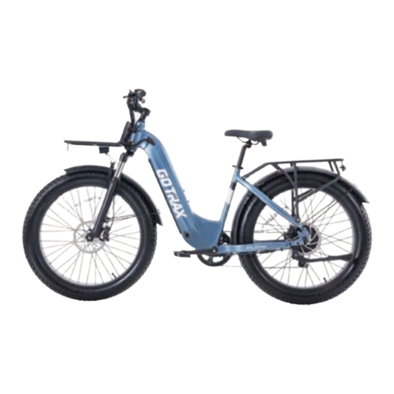
- Page 1 ALPINE E L E C T R I C B I K E...
-
Page 2: Table Of Contents
Contents Congratulationson your purchase ............Don’t Ride Until You Read This .............. Warning Message ................. Unpacking and Product Specs ............... Get To Know Your E-Bike ................ Handlebar Installation ................Saddle Installation ................... Pedal Installation ..................12 Front Wheel Installation ................. Front mudguard, headlight installation .......... -
Page 3: Congratulationson Your Purchase
Congratulations on your purchase! This user manual will help you assemble and operate your new electric bicycle. Be sure to read ALL OF THE INFORMATION in this manual before riding. NOTE TO ALL RIDERS UNDER THE AGE OF 18: It’s very important that you get parental permission before riding your electric bicycle. -
Page 4: Don't Ride Until You Read This
Don’t Ride Until You Read This: ALWAYS wear a helmet when riding your electric bike. Make sure your electric bike has a full battery before taking it out to ride. Always be aware of local road laws, and follow them. Do not ride the bike under the influence of drugs or alcohol. -
Page 5: Warning Message
3. Abuse - We do not cover physical damage due to negligent care and extreme riding. Whenever you ride the GOTRAX Electric Bike ,you risk severe injury or even death from loss of control, collisions, and falls. Use caution and ride at your own risk. - Page 6 16. Make note that additional insurance may be required to cover situations you encounter while riding an electric bike. It is recommended that you contact an insurance company or broker for advice and consultation. 17. To conserve electricity, use assist mode and avoid zero starting, frequent braking, driving against the wind, carrying heavy loads including other people and riding with insufficient air pressure.
- Page 7 ALWAYS WEAR A HELMETIT COULD SAVE YOUR LIFE! A properly fitting, CPSC approved, bicycle helmet should be worn at all times when riding your bicycle. In addition, if you are carrying a passenger (only use an approved child safety seat), and remember, the passenger must also be wearing a helmet.
- Page 8 following measures: *Reorient or relocate the receiving antenna. *Increase the separation between the equipment and receiver. *Connect the equipment into an outlet on a circuit different from that to which the receiver is connected. *Consult the dealer or an experienced radio/TV technician for help.
-
Page 9: Moving And Storage Instructions
Leave it indoor when charging or not riding. WARNING - Risk of Fire - No User Serviceable Parts. Not intended for use at elevations greater than 2000 m above sea level. SAVE THESE INSTRUCTIONS MOVING AND STORAGE INSTRUCTIONS Prolonged Exposure to UV Rays, Rain and the Elements May Damage the Enclosure Materials, Store Indoors When Not in Use. -
Page 10: Unpacking And Product Specs
You should find each of item in you box: Large wrench Allen wrenches Screwdriver Pedal Battery Charger Battery Keys ITEM SPECIFICATIONS Model ALPINE Unfolded Dimensions 1910*700*1190mm Package Dimensions 1510*385*860mm Max Load Weight 150KG(330Ibs) Max Speed 25mph Battery 48Vdc 13.5Ah Input 100-240V 50/60Hz AC Plug;... -
Page 11: Get To Know Your E-Bike
Get To Know Your E-Bike LED Display Saddle Battery Seat Post Pedals Crankset Charger Port Tire Wheel Chain Disc Brake Motor... -
Page 12: Handlebar Installation
Handlebar Installation Use a 5mm hex key to turn counterclockwise to remove the stem cap, then insert the steerer tube into the frame's head tube. After adjusting the handlebar to the desired angle, use the top cap and bolt removed in step one, and tighten the steerer tube top cap first with a 5mm hex key by turning clockwise, then tighten the bolts on both ends of the handlebar. -
Page 13: Saddle Installation
Saddle Installation Find the cushion and seat post. Open the seat clamp quick release; Insert seat tube and adjust position Finally, close the seat clamp quick release and ensure the seat post cannot move or rotate after locking (insert up to the minimum insertion mark, check if the saddle is centered). -
Page 14: Pedal Installation
Pedal Installation Please check the L and R marked pedals. Take a 15mm open-end wrench from the toolbox. Install the right pedal marked with R on Install the left pedal marked with L on the left the right side and tighten it clockwise with side and tighten it counterclockwise with the the 15mm wrench. -
Page 15: Front Wheel Installation
Front Wheel Installation Remove the plastic inserts from inside Remove the protective cover from the front the disc brake calipers (note: the inserts wheel axle, align the front disc brake pad need to be inserted back into the disc duck with the disc brake rim gap, and then brake calipers whenever the front wheel slowly install the wheel onto the fork (note: is removed) -
Page 16: Front Mudguard, Headlight Installation
Front mudguard, headlight installation Find the front mudguard in the packaging Use a 4mm hex key to turn counterclockwise to remove the screws from the fork mudguard fixing plate (one on each side). Use a 5mm Allen wrench to unscrew the screws on the front fork shoulder counterclockwise. -
Page 17: Battery Removal
Battery Remova Slide down the battery cover plate, remove the cover plate, and take out the key from the back of the battery cover. Insert the removed key into the keyhole, turn the key clockwise to unlock the battery, then press down the second lock on the battery to remove it. -
Page 18: Battery Charging
Battery Charging Insert the output of the charger into the battery Red light indicates that the battery is currently and the input into the power supply charging, green light indicates that the battery is fully charged... -
Page 19: Front Rack Installation
Front Rack Installation Find the front rack in the box Using a 4mm Allen wrench turned counterclockwise, remove the front rack Installation screws on the left and right sides of the head tube respectively (four in total) Use a 4mm allen wrench to install the front rack on the head tube by turning clockwise... -
Page 20: Optional Accessories Installation
Optional Accessories Installation Front Basket Installatio Locate the front grocery basket and 4pc Installation screws and nuts After aligning the installation holes of the front basket and the front rack, insert the screws, tighten the nuts, and use a 5mm hex key and 10mm open-end wrench to turn clockwise to lock the screws. - Page 21 Rear Basket Installation Find the rear basket and 4pc fixing screws and nuts. After aligning the installation holes of the rear basket and the rear rack, insert the screws, tighten the nuts, and use a 5mm hex key and 10mm open-end wrench to turn clockwise to lock the screws.
-
Page 22: Tire Inflation Instructions
Tire Inflation Instructions Tires and Tubes After assembling your bike, it will be necessary to inflate the tires. Check the sidewall of the tire for the correct tire pressure (PSI) and inflate tires accordingly with a MANUAL BICYCLE PUMP. Improper inflation is the biggest cause of tire failure. Due to the slightly porous nature of bicycle inner tubes, it is normal for your bike tires to lose pressure over time. - Page 23 Tire pressure is given either as maximum pressure or as a pressure range. How a tire performs under different terrain or weather conditions depends largely on tire pressure. Inflation the tire to near its maximum recommended pressure gives the lowest rolling resistance; but also produces the harshest ride. High pressures work best on smooth, dry pavement.
-
Page 24: User Maintenance Instructions
User Maintenance Instructions Correct routine maintenance of your new bike will ensure a longer life for your bike and a safer ride for you. Every time you ride your bike, its condition changes. The more you ride, the more frequently maintenance will be required. We recommend you spend a little time on regular maintenance tasks. - Page 25 Note: The frequency of maintenance should increase with use in wet or dusty conditions. Do not over lubricate-remove excess bubricant to prevent dirt build up. Never use a degreaser to lubricate your chain (WD-40T™) Schedule2 - Service Checklist NOTE: Many instructions for adjustments can be found in the assembly portion of this manual.
- Page 26 check all nuts and bolts are tight Every six months lubrication as per schedule 1 check all points as per monthly service check and replace brake pads, if required check chain for excess paly or wear lubrication as per schedule 1 Yearly NOTE: OWNERS ARE RESPONSIBLE FOR ALL MAINTENANCE AND SERVICE OF THE BICYCLE.
-
Page 27: Charge Your E-Bike
Charge Your E-Bike You can also charge your battery installed in the bike using the exterior charging port. 1. Locate the charging port. 2. Plug one side of the charger into the charging port and plug the other into an outlet. 3. -
Page 28: Function Definition
Headlight Icon Battery level display Fault Indication Speed Unit Display Real-time Speed Power Assist Push Icon Gear Display Single Trip Mileage Total Travel Distance Maximum Speed Range and Unit Display Average Speed Plus Button Minus Button Confirm "i" Button Power On/Off Button Headlight Button... - Page 29 Power On/Off: Press and hold the button for 2-3 seconds to activate the display and press the button again for 2-3 seconds to turn off the display (the bike will automatically power off , if there is no activity for 10 minutes in a stationary state). Display Data Switching: After the display panel is powered on, it defaults to display- ing real-time, speed and total mileages.
- Page 30 Only when the fault is resolved can you exit the fault display screen. After a fault occurs, the electric bike will not be able to continue to operate. Please contact the GOTRAX after-sales team for assistance or seek the help of a professional technician to diagnose and rectify the issue.
- Page 31 Metric/Imperial Unit Setting: "01P" is the option for selecting metric or imperial units. "00" represents metric and "01" represents imperial Use the button to make the selection, and press the button shortly to save the parameter setting and return to the personalized parameter selection interface. Voltage Setting: "02P"...
- Page 32 Speed Limit Setting: "05p" is the option for setting the speed limit in power assist mode, and the adjustable range for the vehicle speed limit is 10 to 40 km/h. The factory default is 32 km/h, and the maximum limit is 40 km/h. This mode allows you to adjust the speed limit only for power assist mode, as the electric mode has a maximum limit of 32 km/h, which is not adjustable.
- Page 33 To change the password: In the "06P" interface, press the button shortly to enter the parameter change mode.Use the button to select "PSd-y" to enable password change.Press button to confirm and enter the four-digit password setting mode.In the password setting interface, input your new password. Use the button to select the digits and press the button to save each digit and move to the next.
-
Page 34: Battery Information
Battery Information Before using the charger locate the voltage selector switch (li-ion chargers only) on the back of the charger. Select either 115 volts or 230 volts depending on your country of residence. Using the wrong voltage setting will permanenty damage the charger and/or electrical components on the hybrid electric bicycle. -
Page 35: Precautions For Battery Protection
Precautions For Battery Protection 1. Do not place anything on the battery and charger when charging, otherwise the charger may overheat and cause serious damage. 2. Only use the charger supplied by the original factory to charge the battery, if you use a different charger your battery will be disqualified from warranty. -
Page 36: Fault Code
Fault Code Fault code Code Meaning Troubleshooting solutions Inspect the accelerator connection cable; if there is no issue with the connection, Current Anomaly replace the accelerator. Inspect the motor connection cable; if there is no issue with the connection, Throttle Fault replace the motor. -
Page 37: Warranty
Warranty Please contact our customer service team if you are experiencing problems or need more detailed information. support@gotrax.com US team after-sales email: canada@gotrax.com CA team after-sales email: 1. Users should operate in accordance with the product manual. In case of any... - Page 39 (US) W W W .G OT R A X . C O M ( C A ) w w w . g o t r a x c a n a d a . c o m #RideGOTRAX...
- Page 40 (US)GOLABS,INC GOTRAX.com 2201 Luna Rd. Carrollton,TX 75006 (CA)Tao Motor Canada Inc. 170 Bartor Road, Unit 1 North York, Ontario M9M 2W6, Canada.
Need help?
Do you have a question about the ALPINE and is the answer not in the manual?
Questions and answers