Table of Contents
Advertisement
Quick Links
Advertisement
Table of Contents

Related Manuals for TRENDnet TV-IP410


Summary of Contents for TRENDnet TV-IP410
-
Page 2: Reface
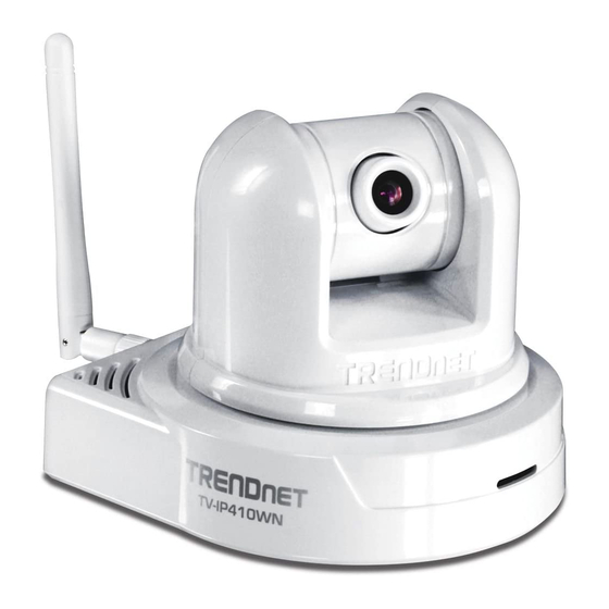
REFACE The Pan/Tilt Internet Camera Server (TV-IP410) /Wireless Pan/Tilt Internet Camera Server (TV-IP410W) provides real-time security surveillance over a large viewing area. Monitor people in your camera’s viewing field and manage the camera from any Internet connection. See more with one Internet camera—remotely pan the camera side-to- side a remarkable 330 degrees and tilt up-and-down 105 degrees. - Page 3 Chapter 6 Appendix provides the specification of the camera and some useful information for using your camera. NOTE The illustrations and configuration values in this guide are for reference only. The actual settings depend on your practical application of the camera. - 2 -...
-
Page 4: Table Of Contents
Contents ..................1 R E F A C E 1 .................. 5 H A P T E R ................5 N T R O D U C T I O N 1.1 P ACKAGE ONTENTS ..............5 1.2 G ........6 ETTING TO AMERA 1.3 F... - Page 5 ™ S ............. 5 8 E C U R I E W O F T W A R E 5.1 I NSTALLATION ................ 58 5.2 U SING NSTALLATION .............. 63 TEM FEATURES ................63 O ADD A CAMERA ................69 O REMOVE A CAMERA ..............
-
Page 6: Introduction
HAPTER NTRODUCTION 1.1 Package Contents The package includes the following: TV-IP410 or TV-IP410W Camera CD-ROM (User’s Guide and Utility) Multi-Language Quick Installation Guide External Antenna (for TV-IP422W only) GPIO Connector RJ-45 Cable 12V 1.5A Power Adapter (3.5mm) ... -
Page 7: Getting To Know Your Camera
1.2 Getting to Know Your Camera Antenna for TV-IP410W Adjustable LEDs only rotate the lens to have clear image. Link LED Power LED indicates the camera’s indicates the camera network connectivity is powered on with with the flashing green the steady amber light. -
Page 8: Rear View
External Antenna Connects the external antenna. Ethernet Cable Connector Connecto to network by using the RJ-45 Cable. It also support the NWay DC Power Connector protocol. connects the AC power adapter, in order to supply power to the camera. GPIO Connectors Reset Button It is used to connect Press it quickly to restart the... -
Page 9: Features And Benefits
1.3 Features and Benefits MJPEG Supported The camera provides you with excellent MJPEG images technology, allowing you to adjust image size and quality, and bit rate according to the networking environment. Optimal Viewing With the pan/tile functions, you can easily monitor everywhere via the camera by moving the camera lens to the left/right (165/165 degrees) or up/down (90/15 degrees). -
Page 10: System Requirement
Through the remote access technology, you can use the cameras to monitor various objects and places for your own purposes. For example, babies at home, patients in the hospital, office, banks, and more. The camera can capture both still images and video clips, so that you can keep the archives and restore them at any time. -
Page 11: C H A P T E
HAPTER ARDWARE NSTALLATION 2.1 Installing the Wall Mount Kit The camera comes with a Wall Mount Kit, which allows you to place your camera anywhere by mounting the camera through the three screw holes located in the base of the Wall Mount Kit. Screw Screw Wall Mount Kit... -
Page 12: Connecting The Camera To Lan/Wlan
2.2 Connecting the Camera to LAN/WLAN Use the provided Ethernet cable to connect the camera to your local area network (LAN). When you connect the AC power adapter, the camera is powered on automatically. You can verify the power status from the Power LED on the front panel of the camera. -
Page 13: Applications Of The Camera
2.3 Applications of the Camera The camera can be applied in multiple applications, including: Monitor local and remote places and objects via Internet or Intranet. Capture still images and video clips remotely. Upload images or send email messages with the still images attached. ... -
Page 14: C C E S S I N G H E A M E R
HAPTER CCESSING AMERA 3.1 Using IPSetup The camera comes with a conveniently utility, IPSetup, which is included in the Installation CD-ROM, allowing you to search the camera on your network easily. 1. Insert the Installation CD-ROM into your computer’s CD-ROM drive to initiate the Auto-Run program. - Page 15 3. Click “Browse” to choose the desired destination location. By default, the destination location is C:\Program Files\TRENDnet\IPSetup. Then Click “Next”. - 14 -...
- Page 16 4. Click “Next” to confirm the IPSetup software to be installed to the computer. 5. When the Installation Complete window appears, click “Finish”. - 15 -...
- Page 17 6. After installing the IPSetup utility, the application is automatically installed to your computer, and creates a folder in “ Start \Program\TRENDnet\IPSetup”. 7. Click Start > Programs > TRENDnet > IPSetup, and then click IPSetup 8. The IPSetup window will appear. The default IP setting is set to DHCP client.
- Page 18 Camera Display Area: It shows the connected camera(s) within the same network Double click the IP address, it will link to Camera’s Web Configuration page. Change IP: Click this button to bring up the following window. It allows you to change the IP Address. You can select either Static IP or click DHCP.
-
Page 19: Accessing To The Camera
Search : Click this button to search the connected camera in the same network.” Exit : Click this button to exit the program. 3.2 Accessing to the Camera 1. Open the Web browser on your computer (example showed in the User’s Guide is based on the Internet Explorer) Type the Camera IP address in the web browser URL (e.g. - Page 20 4. When the login window appears, enter the default User name (admin) and password (admin) and press OK to access to the main screen of the camera’s Web Configuration. - 19 -...
- Page 21 NOTE If you are initially access to the camera, you will be ask to install a new plug-in for the camera. Permission request depends on the Internet security settings of your computer. Click Yes to proceed. After you login into the Web Configuration of the camera, the main page will appear as below: Camera Information Live View/Setup Switch...
-
Page 22: Chapter 4.
Camera Information Displays the camera’s location and the – current date & time. The information can be modified in the Web Configuration. Live View Image Displays the real-time image of the connected – camera. Move your mouse to the Live View area and click on anywhere, the camera lens will then move to the position where you clicked to display it in the central part of Live View area. -
Page 23: Configuring The Ip Address Of The Pc
Auto Patrol button controls the camera to automatically scan the preset positions once. Click Stop to stop patrolling. Click the Number button (1~8) to move the camera lens to the preset position immediately. To set up the preset positions, move the camera lens by clicking the Left/Right/Up/Down buttons to the desired position first, then select the number (1~8) from the pull-down list and click the Apply button. - Page 24 1. On your computer, click Start > Control Panel to open the Control Panel window. 2. Double-click Network Connection to open the Network Connection window. 3. Right-click Local Area Connection and then click Properties from the shortcut menu. 4. When the Local Area Connection Properties window appears, select the General tab.
-
Page 25: C H A P T E
HAPTER ONFIGURING AMERA 4.1 Using the Web Configuration You can access and manage the camera through the Web browser and the provided software application SecurView. This chapter describes the Web Configuration, and guides you through the configuration of the camera by using the Web browser. To configure the camera, click Setup on the main page of Web Configuration. -
Page 26: Using Smart Wizard
Enter the desired camera name and location, then click Apply. You can also configure the camera by using the Smart Wizard as describe below. 4.2 Using Smart Wizard The camera’s Smart Wizard lets you configure your camera easily and quickly. The wizard will guide you through the necessary settings with detailed instructions on each step. - Page 27 changed to new password, please keep a record. You will need the new password to view or configure the camera later on. Step 2. IP Settings Choose DHCP, Static IP or PPPoE - 26 -...
- Page 28 Step 3. Email Settings Enter mail server information for sending still image to email account. Step 4. Wireless Networking Enter wireless network information - 27 -...
- Page 29 Step 5. Confirm Settings Review your setting. Click Apply to save the setting and reboot the camera. Click <Prev to go back to previous setting. Click Cancel to exiting the setting without any changes. - 28 -...
-
Page 30: Basic Setup
4.3 Basic Setup The Basic menu contains three sub-menus that provide the system settings for the camera, such as the Camera Name, Location, Date & Time, and User management. Basic >> System Basic - Camera Name: Enter a descriptive name for the camera. - Location: Enter a descriptive name for the location used by the camera. - Page 31 Basic >> Date & Time - TimeZone: Select the proper time zone for the region from the pull-down menu. - Synchronize with PC: Select this option and the date & time settings of the camera will be synchronized with the connected computer.
- Page 32 Basic >> User Administrator To prevent unauthorized access to the camera’s Web Configuration, you are strongly recommend to change the default administrator password. Type the administrator password twice to set and confirm the password. General User - User Name: Enter the user’s name you want to add to use the camera.
- Page 33 When you are finished, click Add/Modify to add the new user to the camera. To modify the user’s information, select the one you want to modify from UserList and click Add/Modify. - UserList: Display the existing users of the camera. To delete a user, select the one you want to delete and click Delete.
-
Page 34: Network Settings
4.4 Network Settings The Network menu contains three sub-menus that provide the network settings for the camera, such as the IP Setting, DDNS Setting, IP Filter, and Wireless network. Network >> Network IP Setting This item allows you to select the IP address mode and set up the related configuration. - Page 35 - DHCP: Select this option when your network uses the DHCP server. When the camera starts up, it will be assigned an IP address from the DHCP server automatically. - Static IP: Select this option to assign the IP address for the camera directly.
- Page 36 UPnP The camera supports UPnP (Universal Plug and Play), which is a set of computer network protocols that enable the device-to-device interoperability. In addition, it supports port auto mapping function so that you can access the camera if it is behind an NAT router or firewall.
- Page 37 Network >> IP Filter The IP Filter setting allows the administrator of the camera to limit the users within a certain range of IP addresses to access the camera. Start/End IP Address Assign a range of IP addresses that are not allowed to access the camera by entering the Start IP address and End IP address.
- Page 38 Deny IP List The list displays the range setting(s) of IP addresses that are not allowed to access the camera. To clear the setting, select a range of IP addresses from the list and click Delete. Network >> Wireless Setting (For TV-IP410W only) The camera supports WLAN while you use the wireless network.
- Page 39 Ad-Hoc wireless workgroup, set the same wireless channel and SSID to match with the computer’s configuration. Click Site Survey to display the available wireless networks, so that you can easily connect to one of the listed wireless networks. - Wireless Mode: Select the type of wireless communication for the camera: Infrastructure or Ad-Hoc.
- Page 40 type to be interpreted as an eight-bit value in hexadecimal (base 16) notation. Key Length: Select the WEP key length you use: 64 bits or 128 bits. WEP Key 1/2/3/4: Enter the WEP key(s) in the following boxes. If you select WPA-PSK or WPA2-PSK as the Authentication mode, you need to complete the following settings: Encryption: Select TKIP or AES.
-
Page 41: Pan/Tilt Settings
4.5 Pan/Tilt Settings The Pan/Tilt menu allows you to configure the pan/tilt functions of the camera. Pan & Tilt >> Pan & Tilt Settings - Pan/Tilt Calibration: Click Calibration to calibrate the position of the camera lens. - Pan Steps: Set the changing range (1~20 degrees) when you click the Left/Right button. -
Page 42: Setting Up Video
4.6 Setting up Video The Video menu contains three sub-menus that provide the video settings for the camera. Video >> Camera Image Setting - Brightness: Adjust the brightness level from 0 ~ 100. - Contrast: Adjust the contrast level from 0 ~ 100. - Saturation: Adjust the colors level from 0 ~ 100 - 41 -... - Page 43 Click Default to restore the default settings of the three options above. - Mirror: Select the Horizontal option to mirror the image horizontally. Select the Vertical option to mirror the image vertically. - Light Frequency: Select the proper frequency according to the camera’s location: 50Hz, 60Hz, or Outdoor.
- Page 44 MJPEG - Video Resolution: Select the desired video resolution from the three formats: VGA, QVGA and QQVGA. The higher setting (VGA) obtains better video quality while it uses more resource within your network. - Video Quality: Select the desired image quality from five levels: Lowest, Low, Medium, High, and Highest.
- Page 45 - 44 -...
-
Page 46: Event Server Configuration
4.7 Event Server Configuration The Event Server menu contains three sub-menus that allow you to upload images to FTP, send emails that include still images, and store the images to a computer. When you complete the required settings for FTP and Email, click Test to test the related configuration is correct or not. - Page 47 - Password: Enter the password to login into the FTP server. - Directory Path: Enter the destination folder for uploading the images. For example, /Test. - Passive Mode: Select the Enable option to enable passive mode. Event Server Setting >> Email - SMTP Server Address: Enter the mail server address.
- Page 48 - Receiver #1 Email Address: Enter the first email address of the user who will receive the email. - Receiver #2 Email Address: Enter the second email address of the user who will receive the email. - 47 -...
-
Page 49: Motion Detect
4.8 Motion Detect The Motion Detect menu contains the command and option that allow you to enable and set up the motion detection feature of the camera. The camera provides two detecting areas. To enable the detecting area, select Window 1 or 2 from the pull-down list, and then select Enable. -
Page 50: Event Config
4.9 Event Config The Event Config menu contains five sub-menus that provide the commands to configure event profiles. Event Configuration >> General Setting - Snapshot/Recording Subfolder: You can assign a descriptive name for the subfolder to save the captured image/video files. Otherwise, leave this option blank to use the default setting. - Page 51 This sub-menu displays the scheduled profile(s). To customize the profile, click Add and then enter a descriptive name for the profile in the prompt dialog window. Then click OK. The profile is added to the Schedule Profiles list. To delete the profile, select the profile in the list and click Delete.
- Page 52 - Profile Name: Display the profile name that you select in the Schedule Profiles list. - Weekdays: Select the weekday(s) that you want to separately assign in the schedule profile. The weekday that has been assigned will be displayed with green color. - Time List: Display the time period that you have assigned within the selected weekday.
- Page 53 - Schedule Profile: Select a schedule profile from the pull-down list. - Action: Set the Trigger Out function or select the destination of the captured images: Send Email, or FTP Upload. NOTE Setting the Pre-event/Post-event time for sending email or uploading to FTP may cause the system overloads.
- Page 54 then select a Schedule Profile from the pull-down list and set the Interval time. Event Configuration >> GPIO Trigger Select the Enable option to enable the GPIO trigger function of the camera, so that you can set Trigger Out function or send captured images within the detecting area to the FTP server or email receiver,.
- Page 55 - Schedule Profile: Select a schedule profile from the pull-down list. - Action: Set the Trigger Out function or select the destination of the captured images: Send Email, or FTP Upload. NOTE Setting the Pre-event/Post-event time for sending email or uploading to FTP may cause the system overloads.
-
Page 56: Tools
4.10 Tools The Tools menu provides the commands that allow you to restart or reset the camera. You can also backup and restore your configuration, and upgrade the firmware for the camera. Factory Reset Click Reset to restore all factory default settings for the camera. System Reboot ... - Page 57 You can save your camera configuration as a backup file on your computer. Whenever you want to resume the original settings, you can restore them by retrieving the backup file. - Backup: Click Get the backup file to save the current configuration of the camera.
-
Page 58: Information
4.11 Information The Information menu displays the current configuration and events log of the camera. Device Info Display the Basic, Video, Network, and Wireless settings of the camera. System Log The Logs table displays the events log recorded by the system. - 57 -... -
Page 59: C H A P T E
HAPTER ™ S ECUR OFTWARE This Chapter describes detail instructions on operating SecurView™ software, a useful friendly application for ease of control and navigation requirement. Installation 1. Insert the Installation CD-ROM into your computer’s CD-ROM drive to initiate the Auto-Run program. 2. - Page 60 NOTE To use SecurView™, you must have Microsoft .NET Framework 2.0 installed in the computer. The setup wizard will detect it and, if the program is not installed yet, ask you to install it during the process of installing SecurView™. 3.
- Page 61 4. Click “Browse” to choose the desired destination location. By default, the destination location is C:\Program Files\TRENDnet\SecurView. Then Click “Next”. - 60 -...
- Page 62 5. Click “Next” to confirm the SecurView software to be installed to the computer. 6. Click t When the Installation Complete window appears, click “Close”. - 61 -...
- Page 63 7. After installing the IPSetup utility, the application is automatically installed to your computer, and creates a folder in “ Start \Program\TRENDnet\SecurView”. - 62 -...
-
Page 64: Using Installation
Using Installation To launch the program, click Start > Program > TRENDnet > SecurView, and then click SecruView™. The main screen will appear as below. NOTE Please set the resolution to 1024x768 or above on your computer while using SecurView™; otherwise, the displayed main screen may be distorted. - Page 65 CONTROLS Panel - SETTING: Click to enter the Setting screen of SecurView™. Click again to return to the main screen of SecurView™. - PLAY: Click to play the recorded video file using the media player on the computer (for example, Windows Media Player by default). - LOCK: Click to lock the camera controls.
- Page 66 - ALL RECORD: Click to start recording video clips using ALL connected cameras. To stop recording, please click Record button to stop the individual camera. Please note: stop recording only stop the manual recording camera. For schedule recording, please change the setting on configuration. By default, the ID and Password boxes are “blank.”...
- Page 67 - NEXT: When multiple cameras connected, click this button to switch the video view to the next camera. To set the time interval of scanning, click SETTING > Other and then adjust the time from 1 to 10 seconds in the Time interval of scan option.
- Page 68 SYSTEM Panel This panel displays the current date and time. PAN-TILT CONTROL Panel When you connect a pan/tilt camera, the system will detect the camera’s function automatically and the PAN-TILT CONTROL buttons will become functional. Otherwise, these buttons are displayed as gray out buttons.
- Page 69 - SWING: If you have saved two or more positions for the selected camera, click the Swing button ( ) to control the camera swinging from one position to another position. Video View Window and Camera List Video Viewing Window Camera List - Video Viewing Window: This window displays the video view of...
-
Page 70: To Add A Camera
To add a camera 1. Click SETTING in the CONTROLS panel to display the Setting screen. 2. Click Add New Camera. - 69 -... - Page 71 3. In the pop-up Add New Camera dialog window, you can: Select the Search tab if you are not sure of the camera’s IP address. Click Search camera to search the available camera within the network. Once the camera is found and is shown in the list, select it and click Add Camera.
- Page 72 4. Enter the User name and Password for the camera, and then click OK. The connected camera will be displayed in the Camera List. - 71 -...
-
Page 73: To Remove A Camera
5. Click SETTING to return to the Video View Window. The video view of the selected camera will be displayed now. To remove a camera 1. Click SETTING in the CONTROLS panel to display the Setting screen. 2. Select a camera from the list and click Delete Camera. - 72 -... -
Page 74: To Link To The Web Page Of The Camera
Select a camera Delete the camera To link to the Web page of the camera Click SETTING > Camera List > Camera Configuration and then Link web page to launch the Web browser that displays live view image and Web Configuration of the selected camera. - 73 -... -
Page 75: To Record Video
To record video SecurView™ provides three methods to record video clips: one is to click the RECORD/All Record button to record manually; the second is to record by motion detection; the third is to set the recording schedule in Setting > Recording Configuration > Schedule Recording Configuration. - Page 76 Trigger recording by motion detection When the motion detection function of the selected camera is enabled, you can configure the camera to start recording triggered by the motion detected. Click SETTING > Motion Configuration, and then select the Recording option to enable the selected camera to record by motion detection.
- Page 77 Schedule recording Configuration This recording method will work after you have completed the required settings in Schedule Recording Configuration. The recording schedule can be defined by Dates or Days. - Dates: Select the camera from the pull-down list.. - 76 -...
- Page 78 Select a camera Add Schedule - Then, click Add to set the Start/Stop date and time and then click OK to add the recording schedule to the list. - Click Apply to save the settings - 77 -...
- Page 79 - 78 -...
-
Page 80: To Configure The Recording Settings
Days: First, select the camera from the pull-down list and select Days tab. Then, select the weekday from the day buttons and then set the time period. Click Apply to save the settings. To configure the recording settings To configure the recording settings, including the storage folder and storage options, click SETTING >... - Page 81 Recording File Path: To change the destination folder to save the recorded video file, click Browse under the Recording File Path box to assign a new folder. Each Recording File Size: This option allows you to select from 20 ...
-
Page 82: To Playback The Recorded Video
hard disk drive, you can check the available storage space that is displayed in the HDD Free space field. Enable Recycle Recording: Click on the camera number to clear the files when the unreserved space of the hard disk drive is full. To playback the recorded video The recorded video clips are saved in your computer, and can be played using the media player on the computer, such as Windows Media Player. -
Page 83: To Set Up Motion Detection Options
NOTE If your player on the computer don’t have video codec to playback the recorded video. You can download video codec from http://www.xvid.org/downloads.15.0.html to support. To set up motion detection options When the motion detection function of the selected camera is enabled, you can set the Motion Options by selecting Alarm, Recording, Send e- Mail, and Trigger Out under SETTING >... - Page 84 Browse and then selecting your favorite music (*.wav or *.mp3 file) in the computer. Recording: Select this option to enable the camera to record by motion detected. Send Email: Select this option so that the system will be able to ...
-
Page 85: Account
- Mail From: Enter the email address of the user who will send the email. For example, John@mymail.com. - Mail To: Enter the email address of the user who will receive the email. - User Name: Enter the user name to login the mail server. - Password: Enter the password to login the mail server. -
Page 86: Information
Information Click SETTING > About to display the information of the software application. - 85 -... - Page 87 - 86 -...
-
Page 88: Appendix
PPENDIX A.1 Specification Image Sensor Sensor 1/4” color CMOS Resolution 640x480 Video Compression MJPEG Video resolution VGA/QVGA/QQVGA; 30fps max. User Interface One RJ-45 port Antenna One external antenna Reset One Reset button GPIO 1 in/1 out connectors Input: active high: 9~40V DC;... - Page 89 Communication 10/100Mbps Fast Ethernet, auto-sensed, Auto-MDIX WLAN IEEE 802.11b/g Protocol support TCP/IP, UDP, ICMP, DHCP, NTP, DNS, DDNS, SMTP, FTP, PPPoE, UPnP Pan/Tilt 165 degree (left) to 165 degree (right) Tilt 90 degree (up) to 15 degree (down) Software ...
-
Page 90: Gpio Terminal Application
A.2 GPIO Terminal Application Typically used in association with programming scripts for developing applications for motion detection, event triggering, alarm notification via e-mail, and a variety of external control functions. The GPIO connectors are located on the rear panel of the camera, which provide the interface of connecting the sensor device (IN) and controlled device (OUT). -
Page 91: Glossary Of Terms
A.3 Glossary of Terms NUMBERS 10BASE-T 10BASE-T is Ethernet over UTP Category III, IV, or V unshielded twisted-pair media. 100BASE-TX The two-pair twisted-media implementation of 100BASE-T is called 100BASE-TX. ADPCM Adaptive Differential Pulse Code Modulation, a new technology improved from PCM, which encodes analog sounds to digital form. - Page 92 Communication Communication has four components: sender, receiver, message, and medium. In networks, devices and application tasks and processes communicate messages to each other over media. They represent the sender and receivers. The data they send is the message. The cabling or transmission method they use is the medium.
- Page 93 network area. The enterprise network serves the needs of a widely distributed company and operates the company’s mission- critical applications. Ethernet The most popular LAN communication technology. There are a variety of types of Ethernet, including 10Mbps (traditional Ethernet), 100Mbps (Fast Ethernet), and 1,000Mbps (Gigabit Ethernet).
- Page 94 represented as F in the hexadecimal numbering system. The hexadecimal system is useful because it can represent every byte (8 bits) as two consecutive hexadecimal digits. It is easier for humans to read hexadecimal numbers than binary numbers. Intranet This is a private network, inside an organization or company that uses the same software you will find on the public Internet.
- Page 95 communication line. An ISP offers the use of its dedicated communication lines to companies or individuals who can’t afford the high monthly cost for a direct connection. JAVA Java is a programming language that is specially designed for writing programs that can be safely downloaded to your computer through the Internet without the fear of viruses.
- Page 96 Network A network consists of a collection of two or more devices, people, or components that communicate with each other over physical or virtual media. The most common types of network are: LAN – (local area network): Computers are in close distance to one another.
- Page 97 responsible for the presentation and formatting of data for a network operating system are the Internetwork Packet Exchange (IPX) protocol or the Internet Protocol (IP). Protocols that dictate the format of data for transferors the medium include token-passing and Carrier Sense Multiple Access with Collision Detection (CSMA/CD), implemented as token-ring, ARCNET, FDDI, or Ethernet.
- Page 98 subnet mask. (TCP/IP) Transmission Control Protocol/Internet Protocol is a widely used transport protocol that connects diverse computers of various transmission methods. It was developed y the Department of Defense to connect different computer types and led to the development of the Internet. Transceiver A transceiver joins two network segments together.
- Page 99 Windows Windows is a graphical user interface for workstations that use DOS. WPA (Wi-Fi Protected Access ) is used to improve the security of Wi-Fi networks, replacing the current WEP standard. It uses its own encryption, Temporal Key Integrity Protocol (TKIP), to secure data during transmission.
-
Page 100: L Im Ite D W A R R A N T
The repair/replacement unit’s warranty continues from the original date of purchase. All products that are replaced become the property of TRENDnet. Replacement products may be new or reconditioned. TRENDnet does not issue refunds or credit. Please contact the point-of-purchase for their return policies. - Page 101 (RMA) number will be issued. An RMA number is required in order to initiate warranty service support for all TRENDnet products. Products that are sent to TRENDnet for RMA service must have the RMA number marked on the outside of return packages and sent to TRENDnet prepaid, insured and packaged appropriately for safe shipment.
- Page 102 ANY OTHER PERSON TO ASSUME FOR IT ANY OTHER LIABILITY IN CONNECTION WITH THE SALE, INSTALLATION MAINTENANCE OR USE OF TRENDNET’S PRODUCTS. TRENDNET SHALL NOT BE LIABLE UNDER THIS WARRANTY IF ITS TESTING AND EXAMINATION DISCLOSE THAT THE ALLEGED DEFECT IN THE PRODUCT DOES NOT EXIST OR WAS CAUSED BY CUSTOMER’S OR ANY THIRD PERSON’S MISUSE, NEGLECT,...
- Page 103 Download section and look for the desired TRENDnet product to access to the GPL Code or LGPL Code. These codes are distributed WITHOUT WARRANTY and are subject to the copyrights of the developers. TRENDnet does not provide technical support for these codes. Please go http://www.gnu.org/licenses/gpl.txt...
- Page 104 - 103 -...
- Page 105 - 104 -...